Installation instructions
for 49573A L.P. (Propane and
Gas Conversion Kit
Butane)
Converting
10,500
BTU/hr Gas Burners from Natural
Petroleum (Bottled Gas)
Parts included in Kit:
I instruction Sheet
Gas to Liquefied
I Blocking Pin
I Orifice, Burner=Butane No. 64
I Orifice, Burner-Propane No. 62
I Label, Rating Plate Conversion (English)
I Label, Rating Plate Conversion (French)
I Label, Conversion Record (English)
I Label, Conversion Record (French)
I Label, Burner Baseplate (English/French)
NOTE: This instruction sheet contains information for converting two different design gas valves. Read
instructions thoroughly and follow steps.
Warning: This conversion kit shall be installed by a qualified
service agency in accordance with the manufacturer's
instructions and all applicable codes and requirements of the
authority having jurisdiction. The information in these
instructions must be followed to minimize the risk of fire or
explosion or to prevent property damage, personal injury, or
death. The qualified service agency is responsible for the
proper installation of this kit. The installation is not proper and
complete until the operation of the converted appliance is
checked as specified in the manufacturer's instructions
supplied with this kit.
NOTE: A qualified service technician is any person or
representative of a company who is experienced or trained in
servicing gas equipment and is familiar with necessary
precautions.
Canada Only
THIS CONVERSION KIT SHALL BE CARRIED OUT IN
ACCORDANCE WITH THE REQUIREMENTS OF THE
PROVINCIAL AUTHORITIES HAVING JURISDICTION AND
IN ACCORDANCE WITH THE REQUIREMENTS OF THE
CAN-B49.1 AND CAN1-B 149.2 INSTALLATION CODE.
NOTE: Read these instructions before proceeding.
iMPORTANT: The LP Conversion Kit you received is an
approved kit for converting your gas dryer from natural to LP
propane or butane gas. The kit no. shown on the Burner Data
Label located on the Burner Base may not match the kit you
receive due to kit consolidation.
This dryer has been manufactured for use with Natural (city)
gas. Installation of this conversion kit converts the dryer for use
with L.P. gas with manifold pressure of 10" water column and
supply pressure between 8" and 13" water column. If this dryer
is converted for use with L.P. gas by means of this kit, the input
rating will be 10,500 BTU's per hour, for altitudes up to 8,000
feet. For installations above 10,000 feet, contact a qualified
service agency
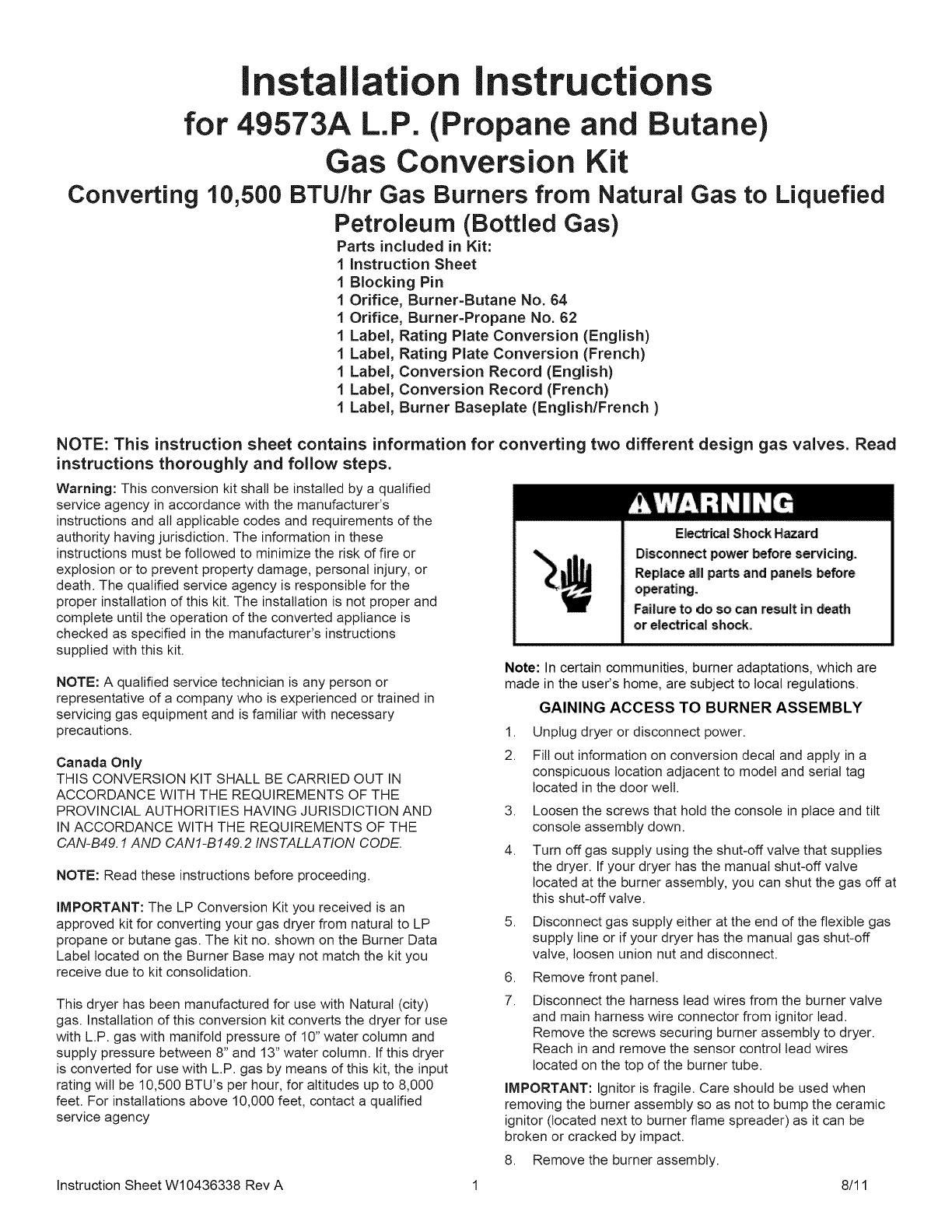
E_icai Shock Hazard
Disconnect: power _fore servicing.
Rep|ace a|! parts and pane_sbefore
operating.
Failure to do so can result in death
or electrical shock.
Note: In certain communities, burner adaptations, which are
made in the user's home, are subject to local regulations.
GAINING ACCESS TO BURNER ASSEMBLY
1. Unplug dryer or disconnect power.
2. Fill out information on conversion decal and apply in a
conspicuous location adjacent to model and serial tag
located in the door welt.
3. Loosen the screws that hold the console in place and tilt
console assembly down.
4. Turn off gas supply using the shut-off valve that supplies
the dryer. If your dryer has the manual shut-off valve
located at the burner assembly, you can shut the gas off at
this shut-off valve.
5. Disconnect gas supply either at the end of the flexible gas
supply line or if your dryer has the manual gas shut-off
valve, loosen union nut and disconnect.
6. Remove front panel.
7. Disconnect the harness lead wires from the burner valve
and main harness wire connector from ignitor lead.
Remove the screws securing burner assembly to dryer.
Reach in and remove the sensor control lead wires
located on the top of the burner tube.
iMPORTANT: Ignitor is fragile. Care should be used when
removing the burner assembly so as not to bump the ceramic
ignitor (located next to burner flame spreader) as it can be
broken or cracked by impact.
8. Remove the burner assembly.
Instruction Sheet W10436338 Rev A 1 8/11