
ElectricandGasDryer
DLE9577WIVl / DLG9588WIVl
as it provides instructions
Maintenance.
and retain the
at http://us.lge.com
iiiiiiiin
P/No.: 3828EL3003M

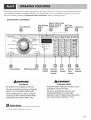
OUTSTANDING PERFORMANCE
Not to mention unmatched big capacity, you can benefit from good
time efficiency, quiet operation and energy saving system.
STAINLESSSTEELDRUM
Stainless steel drum doesn't generate any rust.
ARTISTICDESIGN
Modern front panel look and big crystal-clear glass door make your dryer look stylish.
DIGITALFABRICCARE
Multi-Level temperature control takes better care of your clothes
make operating the dryer easy.
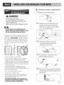
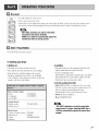
USING THE RIM (REMOTE LAUNDRY MONITOR)
The RLM monitors status of your dryer. You can plug the display unit into any power outlet in your
home. The RLM Display Unit can be purchased separately for this dryer.
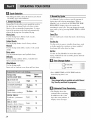
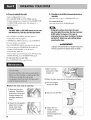
Your dryer provides sensor drying and time drying programs.
Sensor Dry : Dryer electronically sense laundry humidity and it automatically determines operation time based on the
dryness of the load and the selected program. At times, you can see sudden increase or decrease in operation time.
It happens because a sensor will detect laundry humidity within a certain period. Sudden change in operation time is not a
malfunction.
Time Dry : You can manualy set drying time to complete drying. Use dry performance if clothes are still damp after
sensor dry cycle is finished. Time Dry is more effective for heavyweight and bulky items such as king-size bed sheets and
thick work clothes.
J
PART1. SPECIFICATIONS .................................................................................................................................................................................................................. 3
PART2. IMPORTANT WARRANTY AND SAFETY INSTRUCTIONS .............................................................................................................................................. 4-6
PART& INITIAL STEPS FOR INSTALLING YOUR DRYER .......................................................................................................................................................... 7-14
PART4. ACCESSORIES INSTALLATION .................................................................................................................................................................................... 15-16
PART5. ELECTRICAL REQUIREMENTS FOR ELECTRIC DRYER ............................................................................................................................................. 17-20
PART& ELECTRICAL REQUIREMENTS FOR GAS DRYERS .......................................................................................................................................................... 21
PART7. GAS REQUIREMENTS AND INSTRUCTIONS ..................................................................................................................................................................... 22
PART& EXHAUST REQUIREMENTS AND MAINTENANCE ....................................................................................................................................................... 23-24
PARTg. OPERATING YOUR DRYER ............................................................................................................................................................................................ 25-30
PART10. TROUBLESHOOTING GUIDE ........................................................................................................................................................................................ 31-33
LG DRYER LIMITED WARRANTY ...................................................................................................................................................................................................... 34
2

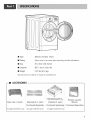
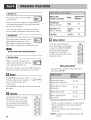
[] Type
[] Rating
[] Size
[] Capacity
[] Weight
Electric and Gas Dryer
Please refer to the rating label regarding detailed information.
27 x 29.9 x 38.7(inch)
IEC 7.3cu.ft. (22.5 Ib)
: 127 Ibs (57.5 kg)
Specifications are subject to change by manufacturer.
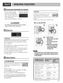
ACCESSORIES
Dryer rack (1 each)
See page 26 for how to use.
Stacking kit (1 each)
Purchased Separately
_': Design of pedestals are subject to
ehange without manafaturers notice.
Pedestal (1 each)
Purchased Separately
Remote Laundry
Monitor
Purchased Separately
See page 13 for how to use. See page 14 for how to use.
3

SEEKING WARRANTY ASSISTANCE
The Warranty for your Dryer is located at the end of this manual. Warranty Service is
available by contacting your nearest LG Service Center. If this product is installed and
operated per this manual, LG will repair or replace any parts defective in material or
workmanship throughout the Warranty period, beginning the Date of Purchase.
RNING!
For your safety_ the recommendations in this manual must be followed. To reduce the risk
of fire or explosion, electric shock or to prevent property damage, personal injury, or death
when using your appliance follow basic precautions, including the following.
Warranty Restriction: If the dryer is subjected to other than private family use, all warranty
coverage is effective for only 90 days.
You will need the complete Model and Serial Number when requesting Warranty Service. Proof of
purchase date is required.
Use the space below to record the model number and serial number of your new LG dryer.
Model No.
Serial No.
Date of Purchase
-_ Staple your receipt HERE.
J

IMPORTANT SAFETY INSTRUCTIONS
WARNING!
To help reduce any risk of electric shock, fire, or other personal injury or property
damage when using your dryer, please exercise care and follow basic safety
1) Read all instructions before using the appliance.
2) Do not dry articles that have come into contact with
gasoline, dry-cleaning solvents, or other flammable
or explosive substances, as they give oft vapors that
could ignite or explode.
8) Do not repair or replace any part of the appliance or
attempt any servicing unless specifically
recommended in the user-maintenance instructions.
9) Do not use heat to dry articles containing foam
rubber or similarly textured rubber-like materials.
3) Do not allow children to play on or in the appliance. 10)
Close supervision of children is necessary when 11)
using the appliance.
4) Before the appliance is removed from service or
discarded, remove the door to the drying
compartment.
5) Do not reach into the appliance if the drum is
moving.
Clean lint screen before or after each load.
6) Do not install or store this appliance where it will be
exposed to the weather.
7) Do not tamper with controls.
Keep area around the exhaust opening and adjacent
surrounding areas fiee fiom the accumulation of
lint, dust, and dirt.
12) The interior of the appliance and exhaust duct
should be cleaned periodically by qualified service
personnel.
13) Do not place items exposed to cooking oils in your
dryer. Items contaminated with cooking oils may
contribute to a chemical reaction that could cause a
load to catch fire.
14) Do not use fabric softners or products to eliminate
static unless recommended by the manufacturer of
the fabric softner or product.
SAVETHESE INSTRUCTIONS
GROUNDING INSTRUCTIONS
This appliance must be grounded. In the event of
mafiunction or breakdown, grounding will reduce the
risk of electric shock by providing a path of least
resistance for electric current. This appliance is
equipped with a cord having an equipment-grounding
conductor and a grounding plug. The plug must be
plugged into an appropriate outlet that is properly
installed and grounded in accordance with all local
codes and ordinances.
WARNING -hnproper connection of the equipment-
grounding conductor can result in a risk of electric
shock. Check with a qualified electrician or service
person if you are in doubt as to whether the appliance is
properly grounded.
Do not modify the plug provided with the appliance.
If it will not fit the outlet, have a proper outlet installed
by a qualified electrician.
This appliance must be connected to a grounded metal
permanent wiring sy stem or an eq uipment -ground ing
conductor must be run with the circuit conductors and
connected to the equipment-grounding terminal or lead
on the appliance.
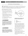
5

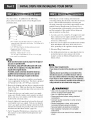
,_ WHAT TO DO IF YOU SMELL
GAS:
• Do not try to light a match or cigarette, or turn
on any gas or electrical appliance.
• Do not touch any electrical switches. Do not
use any phone in your building.
• Clear the room, building or area of all
occupants.
• Immediately call your gas supplier from a
neighbor's phone. Follow the gas supplier's
instructions carefully.
• If you cannot reach your gas supplier, call the
fire department.
WARNING!
• Keep flammable materials and vapors, such
as gasoline, away from dryer.
• Place dryer at least 18 inches above the floor
for a garage installation.
• Failure to do so can result in death,
explosion or fire.
_Ik WARNING
To reduce the risk of fire or explosion, electric
shock, property damage, personal injury or death
when using this appliance, please follow all
instructions and information, including those in
this manual and instructions provided by your
gas supplier.
• Do not store or use any gasoline, dry-cleaning
solvents any other flammable vapors or
liquids in the area surrounding this appliance.
• Do not dry anything that has ever had anything
flammable on it, even after washing.
• No washer can completely remove oil. Do not
dry any articles that have ever had any kind of
oil on them, including cooking oil.
• Articles containing foam, rubber, rubber-like
materials, plastic or similar materials should be
air dried.
• Failure to follow these instructions can result in
fire, death or serious injury.
• A qualified service person or company must
perform installation and service of this
appliance.
California Safe Drinkinq Water
and Toxic Enforcement Act
This act requires the governor of California to
publish a list of substances known to the state to
cause cancer, birth defects or other reproductive
harm and requires businesses to warn customers
of potential exposure to such substances.
Gas appliances can cause minor exposure to four
of these substances, namely benzene, carbon
monoxide, formaldehyde and soot, caused
primarily by the incomplete combustion of
natural gas or LP fuels.
Properly adjusted dryers will minimize
combustion. Exposure to these substances can be
minimized further by properly venting the dryer
to the outdoors.
6

The following instructions will help guide you through the initial steps of setting up your dryer for use.
Please note that every section of this manual provides important information regarding the preparation and
use of your dryer, and it is important that you review this entire manual before proceeding with any
installation or use. More detailed instructions concerning electrical connections, gas connections, and
exhaust requirements are provided in other parts of this manual.
Choose a location with a solid floor for your dryer.
Place the dryer at least eighteen inches above the
floor for a garage installation. After placing the
dryer in the desired location, please make sure that
it has the required clearances shown below. If you
are installing your dryer in a manufactured or
mobile home, please refer to STEP 9 below for
additional instructions.
38.7"
{98.3 cm)
(68.6 cm)
(76.5 cm)
* Most installations require a minimum 5 1/2in.
(14 cm) clearance behind the dryer for the exhaust
vent with elbow.
Leveling legs should be secured.
All four legs are stably placed on the solid and
evenfloor.
if dryer is not level, laundry may not tumble
properly and sensor will net detect the accurate
humidity information.
When leveling, please be cautious not to injure
your fingers and toes.
If you install the dryer on the optional pedstal.
it is nessary to level with the pedestal leveling
legs.
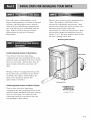
Certain minimum clearances are required
above, behind, and to the sides of the unit, as
shown below. Thoserequired minimum clearances
are set forth in the picture below. Please keep the
t_llowing instructions in mind when installing in a
closet or recessed area:
• Consider allowing additional clearance for
installation and servicing.
• Wall, door and floor molding may force additional
clearances.
• An additional inch of clearance is recommended to
minimize noise transfer.
• Consider space needed t_r companion appliances.
• For closet installations, the picture below shows the
minimnm required ventilation openings t_r the door.
A louvered door with comparable ventilation openings
is also acceptable.
3"
(7.6cm)
48 t_2j
(310 cm2)
24*'2
(155 cm_)..
(7.6cm)
ventilation
hole
v e
ntil ation
hole i _30.1 "_
(2.54cm) (76.5 cm) (2.54cm)
<Closet-Side view><Closet door>
0" _ 27" _1_0"
(0 cm) (68.6 cm) (0 cm)
<Closet-Front view>
7

Once in position, adjust the leveling legs of the dryer
until it is level from left to right and front to back.
The leveling legs must remain firmly on the floor
and the dryer should not rock. The maximum slope
of the dryer from left to right or front to back should
not exceed 2.5 cm (1 inch). If the dryer is not level,
and if the slope exceeds 2.5 cm (1 inch), a load may
not tumble properly and internal sensors may
malfunction. Note: Other sections of this manual
also provide important information concerning the
placement of and clearances for your dryei: Please
review this entire manual before proceeding with any
installation.
iiiiii!i!ilii
i ! i
The door on your dryer can be installed to open
either to the left or the right. Follow these
instructions to reverse the direction in which your
door opens:
Door and latch should be aligned at the center
8

Disassemble
Remove the cap and screw on the right side
of the control panel. Disassemble it by
sliding down to the right for 1 inch.
Push the housing hook and disassemble the
panel.
Disassemble the deco by lifting it up slightly.
Assemble
Connect the housing.
Assemble the control panel by sliding down
the panel to the left until it is perfectly fit.
.... (Details on how to connect the control panel
is illustrated on next page)
Assemble the lower cover to the upper side
of the machine.
_ emove the cap and screw on the right side
of the lower cover. Disassemble it by sliding
down to the right for 1 inch.
9

Assemble
How to assemble the control panel
and lower cover.
Fix the upper deco into the holes. Ill one hole
gets fixed, the others will do automatically.
Assemble the upper deco to the frame.
,%
First of all, put the left side of the panel into
the left side of the frame.
Assemble the upper deco by sliding it down
to the left.
Insert the three of hooks into the holes in the
frame and push it inward.
L lJ
Screw in and fill up the hole with the cap.
Insert the four of hooks into the holes in the
frame and push it inward.
\
I0

WARNING!
• Use a heavy metal vent.
• Do not use plastic or thin foil duct.
• Failure to follow these instructions can
result in death or fire.
•Clean old ducts before installing this dryer
Vent end will face to the outside home and
improper taping and unstable installation of vent
will cause undesirable drying performance,
In addition to the following warnings, please refer
to manual section on Exhaust Requirements and
Maintenance. IMPORTANT: To reduce the risk of
fire, combustion, and gas accumulation, the dryer
must be vented to the outdoors. Please follow the
instructions (and all others in this manual) very
carefully.
• Do not use Plastic or thin foil duct.
• Use 4" (10.2 cm) diameter rigid or Semi-rigid
metal duct (note: venting materials are not
supplied with the dryer, and you should obtain the
venting materials necessary for proper installation)
• Position the Dryer such that the exhaust duct run is
as short as possible.
• Clean old duets beJbre installing this dryer
• The male end of each section of exhaust duct must
point away from the dryer
• Use as few elbow joints as possible.
• Use duct tape on all duct joints
• Insulate ductwork that runs through unheated
areas in order to reduce condensation and lint
build-up on pipe walls.
• PLEASE BE AWARE THAT FAILURE TO
EXHAUST THE DRYER CORRECTLY WILL
VOID THE DRYER'S WARRANTY.
• ALTERNATE EXHAUST DIRECTIONS
Knockout
2-2.
@
Reconnect the duct to the blower
housing and attach the duct to the
base.(Duct is a SVC part)
TAPE
3-1. Pre-assemble 4" elbow with 4" duct.
Wrap duct tape around joint.
DUCT
TAPE
3-2. Insert elbow duct assembly first through the
side opening and connect the elbow to the
internal duct.
11

(Gas dryer only). In addition to the following,
please refer to manual section on Gas Requirements
and Instructions.
I. New stainless steel flexible connector. Use this type of
connector only if allowed by local codes. Use Design AGA
Certified Connector.
2. 1/8" Nl:q" Pipe Plug (for checking inlet gas pressure)
3. Equipment Shut-Off Valve-
Installed within 6' (1.8 m) of dryer
4. Iron Pipe. Shorter than 20' (6.1 m)
Use 3/8" pipe. Longer than 20' (6.1 m) - Use 1/2" pipe.
5.3/8" N.P.T. Gas Connection
Make sure the burner nozzle is proper for the type of
gas you are provided with,
For instance, using LPGwith LNGnozzle will result
in death, fire or explosion, Or using LNGwith LPG
If needed, nozzle conversion should be done by a
qualified service technician and mark or put the
label of the current type of nozzle on the dryer.
1. Confirm that the type of gas available in your laundry
room is appropriate for the dryer. The dryer is prepared
tbr Natural Gas with a 3/8" NPT gas connection.
2. Remove the shipping cap flom the gas connection at the
back of the dryer. Make sure that you don't damage the
threads of the gas connection pipe when you remove the
shipping cap.
3. Connect the dryer to your laundry room's gas supply
using a new flexible stainless steel connector (as noted
below, only use a new stainless steel flexible connector
if allowed by your local codes).
4. Securely tighten all connections between the dryer and
your laundry room's gas supply. Turn on your laundry
room's gas supply and check all pipe connections (both
internal and external) for gas leaks with a non-corrosive
leak detection fluid. Refer to Part 7(page 20)
5. For LP (Liquefied Petroleum) gas connection, refer to
this manual's section entitled Gas Requirements and
Instructions.
12
Following are several warnings and instructions
concerning making the electrical connection t_r electric
dryers. More detailed information concerning the
electrical connection is provided in the manual section
entitled Electrical Requirements for Electric Dryer.
It is important that you thoroughly review that section
and the remainder of this manual, before taking any
steps to install or use this dryer.
1. Use only a new U.L. listed No. 10 (copper wire only)
three conductor power supply cord kit rated 240
Volts (minimum) 30 Amperes and labeled as suitable
for use in a clothes dryer.
2. Four-wire cord is required for manufactured (mobile)
home installations and where local codes do not
allow grounding of this appliance through neutral.
3. Electrical Plug Connections.
4. For additional instruction on connecting the dryer to
an electrical power source, please refer to this
manual's section on Electrical Requirements and
Electric Dryer.
Burnerinputrequirements
if yourhouseis locatedat the elevationup to 10,000
Adjustingburner input setting isnot neededin this
eievatianbecause A.G.Acertifies this dryerwill not
haveany problemwith the B.T.Urating at this altitude,
if yourhouseisabove lO,OOofeet,you arerequired to
adjust a four percent(4%) reduction of the burner B,T.U
rating indicatedon the model/serial
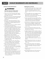
WARNING!
• Use a new UL approved 30 amp power supply
cord or 10 gauge solid copper wire.
•Use a UL approved strain relief.
•Disconnect power before making electrical
connections.
•Connect neutral wire(white or center wire) to
center terminal.
•Ground wire(green or bare wire) must be
connected tO green ground connector.
•Securely tighten all electrical connections
•See installation instructions for complete
instructions,
•Failure to do so can result in fire or electrical
shock

Prior to the first use of this appliance, use all-
purpose cleaning products or a solution of detergent
and water, with damp cloth to remove from the
inside of the dryer drum/drying compartment any
dust or dirt that may have accumulated inside the
dryer. Plug-in your dryer after reviewing the
following parts on your dryer's Electrical
Requirements.
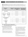
Effective dryer operation requires appropriate dryer
airflow. The adequacy of the airflow can be
measured by evaluating the static pressure. Static
pressure in the exhaust duct can be measured with a
manometer, placed on the exhaust duct
approximately 2 ft. (60.9 cm) from the dryer. Static
pressure in the exhaust duct should not exceed 0.6
inches (1.5 cm). The dryer should be checked while
the dryer is running with no load.
Measuring Static pressure
Confirming Heat Source in Gas Dryers
Close the door to the dryer drum/drying
compartment and, after completing all steps in this
manual for proper installation of this dryer, start the
dryer on a heat setting. After the dryer starts, the
igniter will glow red and the main burner will
ignite.
Warning: If all air is not purged from the gas line,
the gas igniter may go off before the gas and the
main burner have ignited. If this happens, the
igniter will re-attempt gas ignition after
approximately two minutes.
Confirming Heat Source in Electric Dryers
Close the door to the dryer drum/drying
compartment and, after completing all steps in this
manual for proper installation of this dryer, start the
dryer on a heat setting. The exhaust air or the
exhaust pipe should be warm after the dryer has
been operating for three minutes.
Exhaust Duct
MAXIMUM STATIC
PRESSURE IN
WATER COLUMN
0.6 inche (1.5 cm)
Manometer
13

The following instructions are applicable to
installations of the dryer in a manufactured or
mobile home. Any installation in a manufactured or
mobile home must comply with the Manufactured
Home Construction and Safety Standards Title 24
CFR, Part 32-80 or Standard CAN/CSAOZ240 MH
and local codes and ordinances. If you are
uncertain whether your proposed installation will
comply with these standards, please contact a
service and installation professional for assistance.
The following instructions apply to any installation
of the dryer in a manufactured or mobile home:
1) The gas dryer must be permanently attached to
the floor.
2) The electrical connection for an electric dryer
must be a 4-wire connection. More detailed
information concerning the electrical connection
is provided at the manual section entitled
Electrical Requirements for Electric Dryer
3) To reduce the risk of combustion and fire, the
dryer must be vented to the outside.
4) Electric dryers may be vented to the outside
using the back, left, right, or bottom panel.
5) Gas dryers may be vented to the outside using the
back, left, or bottom panel. Gas dryer may not be
vented to the outside using the right side panel
because of the burner housing.
6) The dryer exhaust duct must be affixed securely
to the manufactured or mobile home structure,
and the exhaust duct must be made of a material
that will resist fire and combustion, and it is
recommended that you use a rigid or flexible
metal pipe.
7) DO NOT connect the exhaust duct with any other
duct, vent, chimney, or other exhaust duct.
8) Make sure the dryer has adequate access to
outside fresh air to ensure proper operation. The
opening for outside fresh air must be at least 25
iw' (163 cm_).
9) It is important that the clearance of the duct from
any combustible construction be at least 2 inches
(5 cm), and, when venting the dryer to the
outdoors, the dryer can be installed with a
clearance of 1 inch at the sides and back of the
dryer.
10) Please be aware that venting materials are not
supplied with the dryer. You should obtain the
venting materials necessary for proper
installation.
/(. 7 L_ L
WARNING!
DO NOT connect exhaust ducts with
metal screws or fasteners that extend
into the duct.
WARNING!
DO NOT vent the exhaust duct under the
manufactured or mobile home.
14

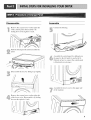
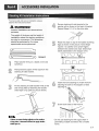
To ensure safe and secure installation, please
observe the instructions below.
WARNING!
Incorrect Installation can cause serious
accidents.
The weight of the dryer and the height of
installation makes the stacking procedure
too risky for one person. This procedure
should be performed by 2 or more
experienced service personnel.
Stackin9kit
Place washer firmly on a stable, even and
solid floor.
Peel protective paper off the tape from the
stacking kit side bracket.
Secure stacking kit side bracket to the
washer with a screw on the back of bracket.
Repeat Steps 2, 3, 4 for the other side.
Place the dryer on top of the washer by fitting
legs as shown in the picture. Avoid finger
injuries - be careful not to pinch fingers
between the washer and dryer. Slide dryer
slowly backwards to the stopper of kit.
Fit the stacking kit side bracket firmly to the
side of top plate by attaching the double-
sided tape to top plate as picture shows.
Insert the front stacking kit. Push the front
stacking kit back to the stoppers of side
stackingk_ _ //
Screw both sides of the front kit.
If there are some foreign objects on the surface
of top plate, it becomes difficult to apply double,
sided tape on.
• Do not use stacking kit with a gas dryer in
potentially unstable conditions like a mobile
home.

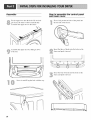
Removepedestal,installationhardware,and
instructionsfromtheshippingcarton.
Position dryer on top of the pedestal.
NOTE • Because of the weight of the dryer
two or more people may be needed.
NOTE : If dryer was previously installed, uninstall
it as follows:
A. Uninstalling an electric dryer:
1) Unplug the power supply cord,
2) Pull the dryer away from the wall enough to
loosen the vent clamp. Loosen the clamp and
carefully remove the exhaust vent from the
dryer exhaust outlet.
B. Uninstalling a gas dryer:
1) Shut off Gas
2) Unplug Power Cord
3) Disconnect Gas Line from Dryer
4) Pull away and loosen vent clamp.
Disconnect venting.
Attach the double-sided tape of the bracket to the
dryer as shown so the bent parts of the brackets
align with the edge and can be attached to the
pedestal with screws.
NOTE : Attach the lower side first.
Be sure to press the adhesive parts of the brackets
firmly to the appliance.
-- for dryer
__ for washer/
combo
combo
Install the eight (8) screws(supplied) to attach the
brackets to the pedestal.
" F
/6
Remove the paper from the
bracket.
Move the dryer to the desired place.
NOTE : The appliance and pedestal assembly
must be placed on a solid and level floor
for proper operation. Adjust the legs of the
appliance and pedestal by turning with a
wrench. Then, adjust the lock unt toward
the pedestal while holding the pedestal leg
using a wrench.

Following are additional instructions regarding electrical connections and requirements for electric dryers.
J_, Important Warning: To help prevent fire, electric shock, serious injury or death, the wiring and grounding
must conform to the latest edition of the National Electrical Code, ANSI/NFPA 70 and all applicable local
regulations. Please contact a qualified electrician to check your home's wiring and fuses to ensure that your home
has adequate electrical power to operate the dryer.
120V/240M 60 Hertz, 3-Wire Installation
Instructions for Grounding of your Electric
Dryer:
a) This dryer must be connected to a grounded
metal, permanent wiring system or an
equipment-grounding conductor must be run
with the circuit conductors and connected to the
equipment-grounding terminal or lead on the
dryer.
b) The dryer has its own terminal block that must
be connected to a separate 60 Hertz single
phaseAC circuit, fused at 30 Amperes (the
circuit must be fused on both sides of the line).
ELECTRICAL SERVICE FOR THE DRYER
SHOULD BE OF MAXIMUM RATE
VOLTAGE LISTED ON THE NAMEPLATE.
DO NOT CONNECT DRYER TO 110, 115,
OR 120 VOLT CIRCUIT. Heating elements are
available for field installation in dryers which
are to be connected to electrical service of
different voltage than that listed on nameplate.
c) If branch circuit to dryer is fifteen feet (4.50 m)
or less in length, use U.L. (Underwriters
Laboratories) listed No. 10 A.W.G. wire (copper
wire only), or as required by local codes. If over
fifteen feet (4.50 m), use U.L. (Underwriters
Laboratories) listed No. 8 A.W.G. wire (copper
wire only), or as required by local codes. Allow
sufficient slack in wiring so dryer can be moved
from its normal location when necessary.
d) The power cord (pigtail) connection between
wall receptacle and dryer terminal block IS NOT
supplied with dryer. Type of pigtail and gauge of
wire must conform to local codes and with
instructions mentioned on the following pages.
e) The method of wiring the dryer is optional and
subject to local code requirements. Refer to
examples on next page.
f) You must select the method by which to wire
your dryer according to local code and ordinance
requirements. Sample methods are included in
the following pages.
17

Review the following options to determine the appropriate electrical connection
for your home:
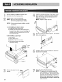
Use the instructions in this section if your home has
a 4-wire receptacle (NEMA type 14-30R) and you
will be using a UL listed, 120/240 volt minimum,
30 amp, dryer power supply cord.
Use the instructions in this section if your home has
a 3-wire receptacle (NEMA type 10-30R) and you
will be using a UL listed, 120/240 volt minimum,
30 amp, dryer power supply cord.
Important : Grounding through the neutral conductor
is prohibited for (1) new branch-circuit installations,
(2) mobile homes, and (3) recreational vehicles, and
(4) areas where local codes prohibit grounding through
the neutral conductor.
Prepare minimum 5fl(l.52m) of length in order for
dryer to be replaced.
First, peel 5 inches (12.7cm) of coveting material from
end. Strip 5 inches of ground wire insulation. After
cutting 172inch (3.8cm) from 3 other wires peel
insulation back linch (2.5cm). Make ends of 3 wires a
hook shape. ¢
If this type is available at your home. you will be
connecting to a fused disconnect or circuit breaker
box
Then, put the hooked shape end of the wire under the
screw of the terminal block(hooked end facing rightward)
and pinch the hook together and screw tightly.
18
If this type is available at your home. you will be
connecting to a fused disconnect or circuit breaker
box
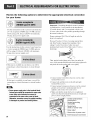
• Screw power supply wire to the terminal block.
Colored wire should be connected to same color
screw. Wire color indicated on manual is
connected to the same color screw in block.
Otherwise, excessive current is applied resulting
in damages on product and heating failure.
1. Connect neutral wire(white) of power cord to center
terminal block screw.
2. Connect red and black wire to the left and right
terminal block screws.
3. Connect ground wire(green) of power cord to external
ground screw and move neutral ground wire of
appliance and connect it to center screw.
4. Make sure that the strain relief screw is tightened.
and be sure that all terminal block nuts are on tight and
power cord is in right position.
Center terminal block
screw(silver)
Neutral grounding
wire(white)
Neutral wire
(white or center wire)
Strain relief
Green wire of power cord
External ground connector

Important : Grounding through the neutral conductor
is prohibited for (1) new branch-circuit installations,
(2) mobile homes, and (3) recreational vehicles, and
(4) areas where local codes prohibit grounding through
the neutral conductor.
Prepare minimum 5ft(l.52m) of length in order for
dryer to be replaced.
First, strip 3 72 inches (8.9cm) of outer sheath from
end and strip 1 inch of insulation from each
conductor.
Then, put the hooked shape end of the wire under
the screw of the terminal block(hooked end facing
rightward) and pinch the hook together and screw
tightly.
1. Connect neutral wire(white) of power cord to
center terminal block screw.
2. Connect red and black wire to the left and right
terminal block screws.
3. Make sure that the strain relief screw is tightened
and be sure that all terminal block nuts are on
tight and power cord is in right position.
Center terminal
block screw(silver)
Neutral grounding
wire(white)
Neutral grounding
wire(white)
relief
External ground
connector
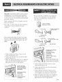
• If your local codes or ordinances do not allow the
use of a 3 wire connection, or you are installing
your dryer in a mobile home, you must use a 4-
wire connection.
(N4-wirereceptacle
EMAtype 14-30R)
nt plug _ SPtadnetc_remnicnalswith
_ee uG[°lUpdoPrgOng
4-pront plug _ 3/4 in. (1.9 cm)
proved strain relief
doPgng Ring terminals
Center terminal block
screw(silver)
Neutral grounding
wire(white)
Neutral wire
(white or center wire)
Strain relief
Green wire of power cord
External ground connector
1. Connect neutral wire(white) of power cord to
center terminal block screw.
2. Connect red and black wire to the left and right
terminal block screws.
3. Connect ground wire(green) of power cord to
external ground screw and move neutral ground
wire of appliance and connect it to center screw.
4. Make sure that the strain relief screw is tightened.
and be sure that all terminal block nuts are on
tight and power cord is in right position.
19

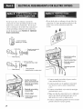
If your local codes or ordinances permit the
connection of a frame-grounding conductor to the
neutral wire, use these instructions. If your local
codes or ordinances do not allow the connection of
a frame-grounding conductor to the neutral wire,
use the instructions under Section 3: Optional
3-wire connection.
• If your local codes or ordinances do not allow the
connection of a frame-grounding conductor to the
neutral wire, use the instructions under this
section.
_( 3-wire receptacle
NEMA type I0-30R)
3-wire plug _ S_)ade terminals with
15turned ends
ron_
_a _ 3-wire plug _ 3/4 in. (1.9 cm)
pproved strain relief
rona= Ring terminals
r _ _Neutral (white or center wire)
Neutral grounding
wire(Green)
Neutral wire(white)
External ground
connector
--Separate ground
_._lre
l
Center terminal
block screw(silver)
Neutral grounding
wire(white)
Neutral grounding
wire(white)
Strain relief
External ground
connector
.
2.
.
4.
.
Connect neutral wire(white) of power cord to
center terminal block screw.
Connect ground wire of appliance and neutral
wire of power cord to center terminal block
screw.
Connect red and black wire to the left and right
terminal block screws.
Make sure that the strain relief screw is tightened.
and be sure that all terminal block nuts are on
tight and power cord is in right position.
Connect a independent ground wire from external
ground connector to proper ground.
2O
Page is loading ...
Page is loading ...
Page is loading ...
Page is loading ...
Page is loading ...
Page is loading ...
Page is loading ...
Page is loading ...
Page is loading ...
Page is loading ...
Page is loading ...
Page is loading ...
Page is loading ...
Page is loading ...
-
 1
1
-
 2
2
-
 3
3
-
 4
4
-
 5
5
-
 6
6
-
 7
7
-
 8
8
-
 9
9
-
 10
10
-
 11
11
-
 12
12
-
 13
13
-
 14
14
-
 15
15
-
 16
16
-
 17
17
-
 18
18
-
 19
19
-
 20
20
-
 21
21
-
 22
22
-
 23
23
-
 24
24
-
 25
25
-
 26
26
-
 27
27
-
 28
28
-
 29
29
-
 30
30
-
 31
31
-
 32
32
-
 33
33
-
 34
34


LG DLG9588WM Owner's manual
- Category
- Electric laundry dryers
- Type
- Owner's manual
Ask a question and I''ll find the answer in the document
Finding information in a document is now easier with AI
Related papers
Other documents
-
Maytag MED9600SQ0 Quick start guide
-
Frigidaire FLCG7522AW User guide
-
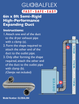 GLOBALFLEX Global004 Operating instructions
-
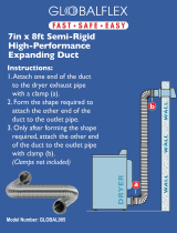 GLOBALFLEX Global005 Operating instructions
-
Frigidaire GLGQ2170KS0 Installation guide
-
Crosley CDG7500KB0 Installation guide
-
LG Electronics D2532W User manual
-
-
Beko BDV7200X Owner's manual
-
Kenmore Elite 9.0 cu. ft. Electric Dryer - White Owner's manual

