Page is loading ...
Please read this manual carefully before operating
your set.
Retain it for future reference.
Record model number and serial number of the set.
See the label attached on the back cover and quote
this information to your dealer
when you require service.
LCD TV PLASMA TV
OWNER’S MANUAL
LCD TV MODELS
32LG30 37LG50
37LG30 42LG50
42LG30 47LG50
52LG50
32LG60 32LG70
37LG60 42LG70
42LG60 47LG70
47LG60 52LG70
52LG60
PLASMA TV MODELS
42PG25
50PG25
50PG60
60PG60
P/NO : MFL34797048 (0803-REV04)
Printed in Korea
www.lgusa.com
As an ENERGY STAR
Partner LGE U. S. A.,Inc.
has determined that this
product meets the
ENERGY STAR guidelines
for energy efficiency.
ENERGY STAR is a set of power-saving
guidelines issued by the U.S.
Environmental Protection Agency(EPA).
An extended owner’s manual that contains information
on the advanced features of these LG TV sets is located
on the CD-ROM provided in an electronic version.
To read these files, you will need to use personal computer
(PC) equipped with a CD-ROM drive.
MFL34797048-en-4 3/18/08 7:26 PM Page 1

2
WARNING / CAUTION
WARNING / CAUTION
To prevent fire or shock hazards, do not expose
this product to rain or moisture.
FCC NOTICE
Class B digital device
This equipment has been tested and found to com-
ply with the limits for a Class B digital device, pur-
suant to Part 15 of the FCC Rules. These limits are
designed to provide reasonable protection against
harmful interference in a residential installation. This
equipment generates, uses and can radiate radio fre-
quency energy and, if not installed and used in
accordance with the instructions, may cause harmful
interference to radio communications. However,
there is no guarantee that interference will not
occur in a particular installation. If this equipment
does cause harmful interference to radio or televi-
sion reception, which can be determined by turning
the equipment off and on, the user is encouraged to
try to correct the interference by one or more of
the following measures:
- Reorient or relocate the receiving antenna.
- Increase the separation between the equipment
and receiver.
- Connect the equipment to an outlet on a circuit
different from that to which the receiver is con-
nected.
- Consult the dealer or an experienced radio/TV
technician for help.
Any changes or modifications not expressly
approved by the party responsible for compliance
could void the user’s authority to operate the
equipment.
CAUTION
Do not attempt to modify this product in any way
without written authorization from LG Electronics.
Unauthorized modification could void the user’s
authority to operate this product
The lightning flash with arrowhead
symbol, within an equilateral triangle,
is intended to alert the user to the
presence of uninsulated “dangerous voltage”
within the product’s enclosure that may be of
sufficient magnitude to constitute a risk of electric
shock to persons.
The exclamation point within an equilateral
triangle is intended to alert the user to
the presence of important operating and main-
tenance (servicing) instructions in the literature
accompanying the appliance.
TO REDUCE THE RISK OF ELECTRIC SHOCK
DO NOT REMOVE COVER (OR BACK). NO
USER SERVICEABLE PARTS INSIDE. REFER TO
QUALIFIED SERVICE PERSONNEL.
WARNING/CAUTION
TO REDUCE THE RISK OF FIRE AND ELECTRIC
SHOCK, DO NOT EXPOSE THIS PRODUCT TO
RAIN OR MOISTURE.
NOTE TO CABLE/TV INSTALLER
This reminder is provided to call the CATV system
installer’s attention to Article 820-40 of the National
Electric Code (U.S.A.). The code provides guidelines for
proper grounding and, in particular, specifies that the
cable ground shall be connected to the grounding sys-
tem of the building, as close to the point of the cable
entry as practical.
MFL34797048-en-4 3/18/08 7:26 PM Page 2
3
IMPORTANT SAFETY INSTRUCTIONS
SAFETY INSTRUCTIONS
Important safety instructions shall be provided with each apparatus. This information shall be given in a separate
booklet or sheet, or be located before any operating instructions in an instruction for installation for use and
supplied with the apparatus.
This information shall be given in a language acceptable to the country where the apparatus is intended to be used.
The important safety instructions shall be entitled “Important Safety Instructions”. The following safety
instructions shall be included where applicable, and, when used, shall be verbatim as follows. Additional safety
information may be included by adding statements after the end of the following safety instruction list. At the
manufacturer’s option, a picture or drawing that illustrates the intent of a specific safety instruction may be
placed immediately adjacent to that safety instruction:
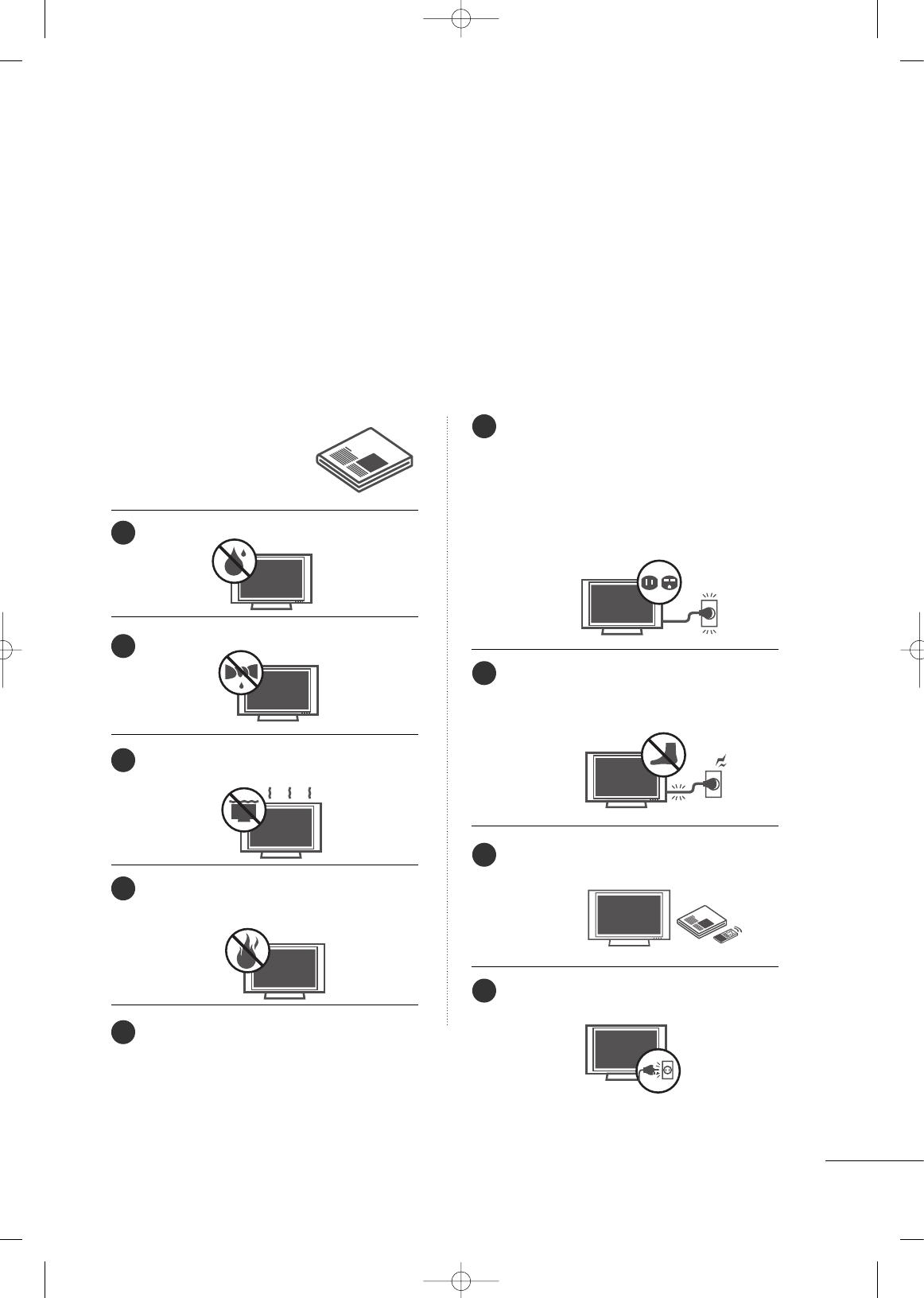
Read these instructions.
Keep these instructions.
Heed all warnings.
Follow all instructions.
Do not use this apparatus near water.
Clean only with dry cloth.
Do not block any ventilation openings. Install in
accordance with the manufacturer’s instructions.
Do not install near any heat sources such as
radiators, heat registers, stoves, or other apparatus
(including amplifiers)that produce heat.
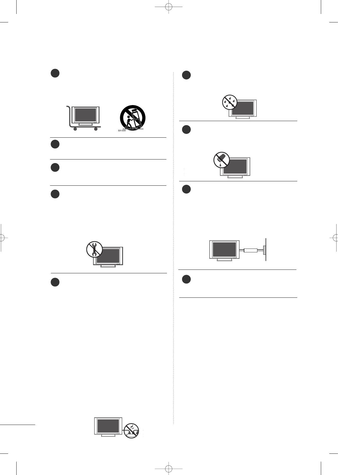
When mounting a TV it on the wall, make sure
not to install TV by hanging power and signal
cables on the back of the TV.
Do not defeat the safety purpose of the polarized
or grounding-type plug. A polarized plug has
two blades with one wider than the other. A
grounding type plug has two blades and a third
grounding prong, The wide blade or the third
prong are provided for your safety. If the provided
plug does not fit into your outlet, consult an
electrician for replacement of the obsolete outlet.
Protect the power cord from being walked on
or pinched particularly at plugs, convenience
receptacles, and the point where they exit from
the apparatus.
Only use attachments/accessories specified by
the manufacturer.
Unplug this apparatus when unused for long
periods of time.
1
2
3
4
5
6
7
8
9
MFL34797048-en-4 3/18/08 7:26 PM Page 3
4
SAFETY INSTRUCTIONS
Use only with the cart, stand, tripod, bracket,
or table specified by the manufacturer, or sold
with the apparatus. When a cart is used, use
caution when moving the cart/apparatus
combination to avoid injury from tip-over.
Never touch this apparatus or antenna during
a thunder or lighting storm.
Do not allow a impact shock or any objects to
fall into the product, and do not drop onto the
screen with something.
Refer all servicing to qualified service personnel.
Servicing is required when the apparatus has
been damaged in any way, such as power-supply
cord or plug is damaged, liquid has been
spilled or objects have fallen into the apparatus,
the apparatus has exposed to rain or moisture,
does not operate normally, or has been
dropped.
CAUTION concerning the Power Cord :
Most appliances recommend they be placed
upon a dedicated circuit; that is, a single outlet
circuit which powers only that appliance and
has no additional outlets or branch circuits.
Check the specification page of this owner's
manual to be certain.
Do not overload wall outlets. Overloaded wall
outlets, loose or damaged wall outlets, extension
cords, frayed power cords, or damaged or
cracked wire insulation are dangerous. Any of
these conditions could result in electric shock
or fire. Periodically examine the cord of your
appliance, and if its appearance indicates dam-
age or deterioration, unplug it, discontinue use
of the appliance, and have the cord replaced
with an exact replacement part by an authorized
servicer. Protect the power cord from physical
or mechanical abuse, such as being twisted,
kinked, pinched, closed in a door, or walked
upon. Pay particular attention to plugs, wall
outlets, and the point where the cord exits the
appliance.
Outdoor use marking :
WARNING - To reduce the risk of fire or elec-
tric shock, do not expose this appliance to rain
or moisture.
Wet Location Marking : Apparatus shall not be
exposed to dripping or splashing and no
objects filled with liquids, such as vases, shall
be placed on or over apparatus.
GGRROOUUNNDDIINNGG
Ensure that you connect the earth ground wire
to prevent possible electric shock. If grounding
methods are not possible, have a qualified
electrician install a separate circuit breaker.
Do not try to ground the unit by connecting it
to telephone wires, lightening rods, or gas pipes.
DDIISSCCOONNNNEECCTTIINNGG DDEEVVIICCEE FFRROOMM MMAAIINNSS
Mains plug is the disconnecting device. The
plug must remain readily operable.
FOR LCD TV
■
If the TV feels cold to the touch, there may be a
small “flicker” when it is turned on. This is normal,
there is nothing wrong with TV.
■
Some minute dot defects may be visible on the
screen, appearing as tiny red, green, or blue spots.
However, they have no adverse effect on the monitor's
performance.
■
Avoid touching the LCD screen or holding your
finger(s) against it for long periods of time. Doing
so may produce some temporary distortion effects
on the screen.
On Disposal
The fluorescent lamp used in this product contains a
small amount of mercury. Do not dispose of this
product with general household waste. Disposal of
this product must be carried out in accordance to the
regulations of your local authority.
12
10
11
13
14
15
16
18
17
Power
Supply
Short-circuit
Breaker
MFL34797048-en-4 3/18/08 7:26 PM Page 4

5
CONTENTS
HOW TO USE THE OWNER'S MANUAL ON THE CD-ROM
To view the Owner's Manual on the CD-ROM, Adobe Acrobat Reader must be installed on your PC.
The “ACRORD" folder on the CD-ROM contains the installation programs for them.
If you want to install those programs, Open the “My Computer” Open the “LG” Open the
“ACRORD” double-click your language.
TO VIEW THE OWNER'S MANUAL ON THE CD-ROM
The Owner's Manual files are included in the supplied CD-ROM.
Load the supplied CD-ROM into the CD-ROM drive of your PC.
After a while, the web page of the CD-ROM will open automatically. (for Window only)
GG
If the web page does not appear automatically, open the Owner's Manual file directly.
Open the “My computer” Open the “LG” Open the “index.htm” file.
NOTE
!
When you select your product,
display the PDF file.
You can find the desired contents
easily using the bookmark.
WARNING / CAUTION
. . . . . . . . . . . . . . . . . . . . . . . . . . . . 2
SAFETY INSTRUCTIONS
. . . . . . . . . . . . . . . . . . . . . . . . . . 3
PREPARATION
Accessories . . . . . . . . . . . . . . . . . . . . . . . . . . . . . . . . . . . . . . . . . . . . . . . . . . . . . . 6
Front Panel Information
. . . . . . . . . . . . . . . . . . . . . . . . . . . . . . . . . . . . . .7
Back Panel Information
. . . . . . . . . . . . . . . . . . . . . . . . . . . . . . . . . . . . . . 8
Remote Control Functions
. . . . . . . . . . . . . . . . . . . . . . . . . . . . . . . 10
Stand Installation
. . . . . . . . . . . . . . . . . . . . . . . . . . . . . . . . . . . . . . . . . . . . 12
Cable Management
. . . . . . . . . . . . . . . . . . . . . . . . . . . . . . . . . . . . . . . . . 14
Desktop Pedestal Installation
. . . . . . . . . . . . . . . . . . . . . . . . . . . . 16
Swivel Stand
. . . . . . . . . . . . . . . . . . . . . . . . . . . . . . . . . . . . . . . . . . . . . . . . . . . . 16
Attaching the TV to a Desk
. . . . . . . . . . . . . . . . . . . . . . . . . . . . . . 16
VESA Wall Mounting
. . . . . . . . . . . . . . . . . . . . . . . . . . . . . . . . . . . . . . . . 17
Protection Cover
. . . . . . . . . . . . . . . . . . . . . . . . . . . . . . . . . . . . . . . . . . . . . 18
Securing the TV to the Wall to prevent falling
. . . 19
Antenna or Cable Connection
. . . . . . . . . . . . . . . . . . . . . . . . . . 20
EXTERNAL EQUIPMENT SETUP
HD Receiver Setup . . . . . . . . . . . . . . . . . . . . . . . . . . . . . . . . . . . . . . . . . 21
DVD Setup
. . . . . . . . . . . . . . . . . . . . . . . . . . . . . . . . . . . . . . . . . . . . . . . . . . . . . 22
VCR Setup
. . . . . . . . . . . . . . . . . . . . . . . . . . . . . . . . . . . . . . . . . . . . . . . . . . . . . 23
PC Setup
. . . . . . . . . . . . . . . . . . . . . . . . . . . . . . . . . . . . . . . . . . . . . . . . . . . . . . . . 24
WATCHING TV
Turning On TV . . . . . . . . . . . . . . . . . . . . . . . . . . . . . . . . . . . . . . . . . . . . . . . . 26
Channel Setup
. . . . . . . . . . . . . . . . . . . . . . . . . . . . . . . . . . . . . . . . . . . . . . . . 26
Quick Menu
. . . . . . . . . . . . . . . . . . . . . . . . . . . . . . . . . . . . . . . . . . . . . . . . . . . . 27
On-Screen Menus Selection
. . . . . . . . . . . . . . . . . . . . . . . . . . . . . 27
USB
Entry Modes . . . . . . . . . . . . . . . . . . . . . . . . . . . . . . . . . . . . . . . . . . . . . . . . . . . 30
Photo List
. . . . . . . . . . . . . . . . . . . . . . . . . . . . . . . . . . . . . . . . . . . . . . . . . . . . . . . 31
Music List
. . . . . . . . . . . . . . . . . . . . . . . . . . . . . . . . . . . . . . . . . . . . . . . . . . . . . . . 33
APPENDIX
Troubleshooting . . . . . . . . . . . . . . . . . . . . . . . . . . . . . . . . . . . . . . . . . . . . . . 35
Maintenance
. . . . . . . . . . . . . . . . . . . . . . . . . . . . . . . . . . . . . . . . . . . . . . . . . . . 36
Product Specifications
. . . . . . . . . . . . . . . . . . . . . . . . . . . . . . . . . . . . . 37
Open Source Software Notice
. . . . . . . . . . . . . . . . . . . . . . . . . . 39
MFL34797048-en-4 3/18/08 7:26 PM Page 5
PREPARATION
6
PREPARATION
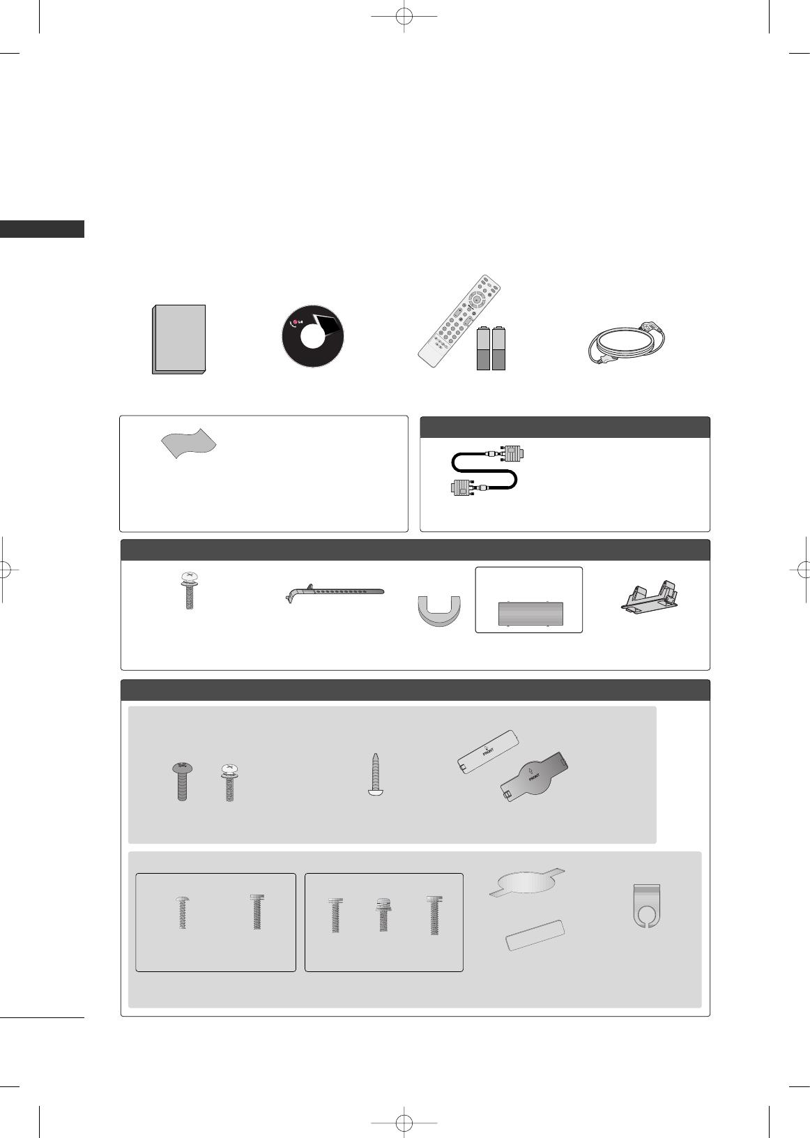
ACCESSORIES
Ensure that the following accessories are included with your TV. If an accessory is missing, please contact the
dealer where you purchased the product.
The accessories included may differ from the images below.
For further information, see the the Owner's Manual files supplied CD-ROM.
OOppttiioonn EExxttrraass
FFoorr LLCCDD TTVV mmooddeellss
FFoorr PPllaassmmaa TTVV mmooddeellss
* Wipe spots on the exterior only with
the polishing cloth.
* Do not wipe roughly when removing
stain. Please be cautions of that
excessive pressure may cause scratch
or discoloration.
Polishing Cloth
(This feature is not available
for all models.)
Copyright© 2007 LGE,
All Rights Reserved.
D-sub 15 pin Cable
1.5V 1.5V
Owner’s Manual Power Cord
Remote Control,
Batteries
INPUT
FAV
MUTE
T
V
S
T
B
POWER
Q. MENU
MENU
AV MO DERETURN
E
N
T
E
R
VOL
CH
123
456
78
0
9
FLASHBK
P
A
G
E
D
V
D
V
C
R
CD Manual
(Refer to p.5)
When using the VGA (D-sub 15 pin
cable) PC connection, the user
must use shielded signal interface
cables with ferrite cores to maintain
standards compliance.
32/37/42LG30, 37/42/47/52LG50, 32/42/47/52LG70
Bolts for stand assembly
(Refer to P.12)
(Only 32/37/42LG30, 37/42LG50,
32/42LG70)
Protection Cover
(Refer to P.18)
Screw for stand fixing
(Refer to P.16)
(Only 32LG30/70)
x 4 x 4
32/37/42/47/52LG60
Protection Cover
(Refer to P.18)
Cable Management
Clip
2EA
(M4x16)
4EA
(M4x20)
1EA 4EA 32LG60: 3EA
37LG60: 4EA
Bolts for stand assembly
(Refer to P.13)
(Only 32/37LG60) (Only 42LG60)
Cable Management Clip
Protection Cover
(Refer to P.18)
Cable Holder
(Only 42PG25)
(Only 50PG25,
50/60PG60)
(Only 42PG25)
or
Bolts for stand assembly
(Refer to P.12)
x 4
or
MFL34797048-en-4 3/18/08 7:27 PM Page 6
PREPARATION
7
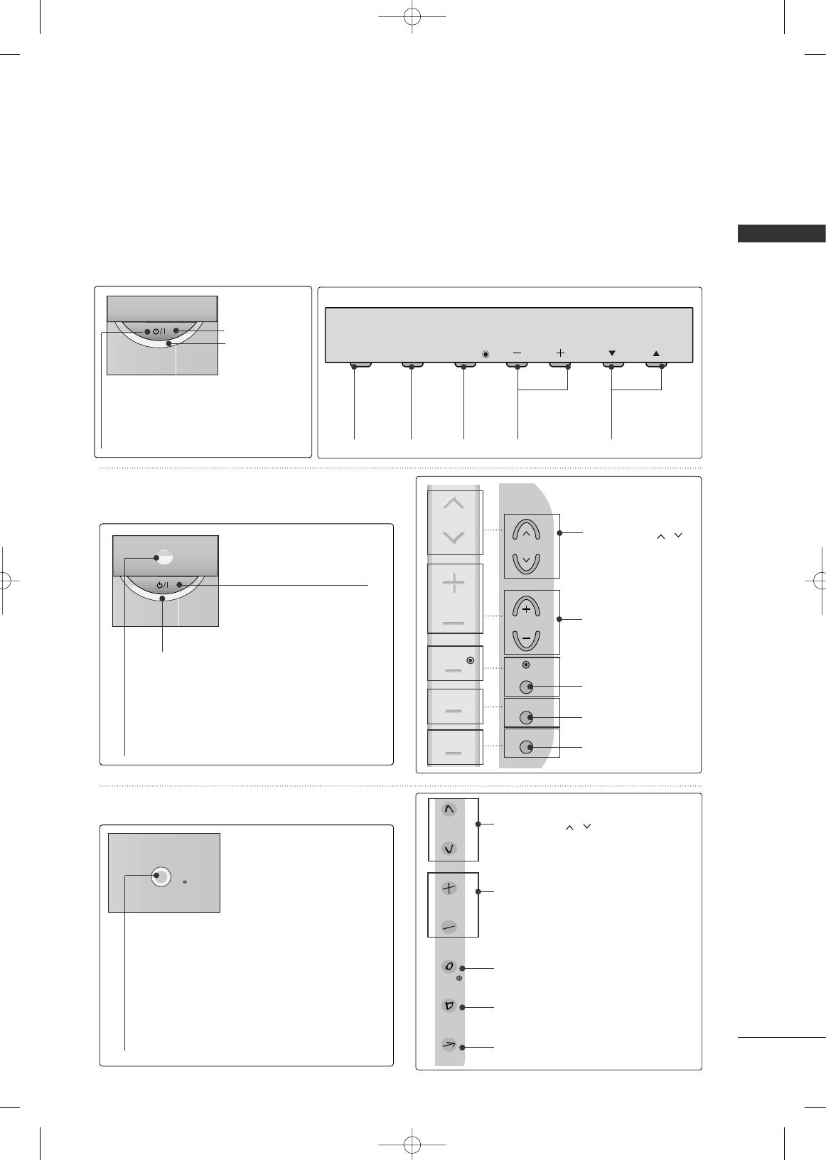
FRONT PANEL INFORMATION
■
Image shown may differ from your TV.
■
NOTE: If your TV has a protection tape attached, remove the tape.
And then wipe the TV with a cloth (If a polishing cloth is included with your TV, use it).
CH
VOL
MENU
INPUT
ENTER
INPUT
Button
MENU
Button
ENTER
Button
VOLUME
(-, +) Buttons
CHANNEL
(
EE
,
DD
)Buttons
CH
VOL
MENU
INPUT
ENTER
Remote Control
Sensor
POWER Button
Power/Standby Indicator
Illuminates red in standby mode.
Illuminates blue when the TV is
switched on.
ENTER
CH
VOL
MENU
INPUT
CHANNEL ( , ) Buttons
VOLUME (+, -) Buttons
ENTER Button
MENU Button
INPUT Button
CH
VOL
MENU
INPUT
ENTER
CHANNEL ( , )
Buttons
VOLUME (+, -)
Buttons
ENTER Button
MENU Button
INPUT Button
CH
VOL
MENU
INPUT
ENTER
POWER Button
Power/Standby Indicator
Illuminates red in standby mode.
Illuminates blue when the TV is switched on.
(Can be adjusted using
PPoowweerr IInnddiiccaattoorr
in
the OPTION menu.)
Remote Control Sensor
POWER Button
Remote Control Sensor
Power/Standby Indicator
Illuminates red in standby mode.
Illuminates white when the TV is switched on.
(Can be adjusted using
PPoowweerr IInnddiiccaattoorr
in
the OPTION menu.)
Plasma TV Models
32/37/42LG30, 37/42/47/52LG50,
32/42/47/52LG70
32/37/42/47/52LG60
MFL34797048-en-4 3/18/08 7:27 PM Page 7
PREPARATION
8
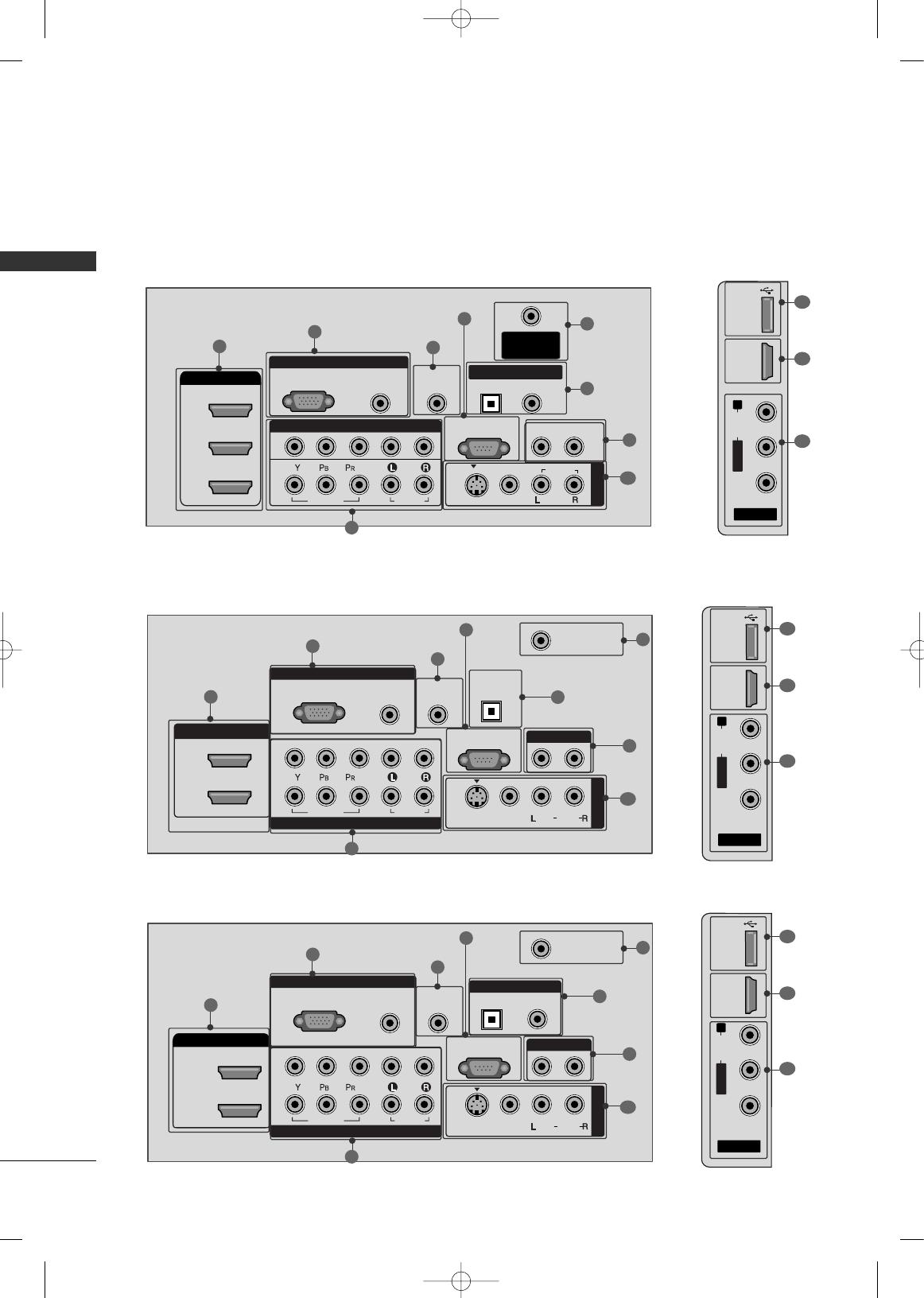
BACK PANEL INFORMATION
PREPARATION
■
Image shown may differ from your TV
R
RGB IN
COMPONENT IN
AUDIO
(RGB/DVI)
RGB(PC)
ANTENNA/
CABLE IN
1
2
RS-232C IN
(CONTROL & SERVICE)
VIDEO
AUDIO
VIDEO
AUDIO OUT
OPTICAL COAXIAL
MONO
( )
AUDIO
S-VIDEO
DIGITAL AUDIO OUT
AV IN 1
HDMI/DVI IN
3
2
1
REMOTE
CONTROL IN
1
3
4
6
7
8
2
9
5
AV IN 2
L/MONO
R
AUDIO
VIDEO
USB IN
HDMI IN 4
( )
9
10
1
Plasma TV Models
LCD TV Models
AV IN 2
L/MONO
R
AUDIO
VIDEO
HDMI IN 3 USB IN
( )
RGB IN
COMPONENT IN
AUDIO
(RGB/DVI)
RGB(PC)
REMOTE
CONTROL IN
ANTENNA/
CABLE IN
1
2
RS-232C IN
(CONTROL & SERVICE)
VIDEO
AUDIO
OPTICAL COAXIAL
DIGITAL AUDIO OUT
AUDIO OUT
AV IN 1
R
HDMI/DVI IN
2
1
VIDEO
MONO
( )
AUDIO
S-VIDEO
1
3
4
6
7
8
2
9
9
5
RGB IN
COMPONENT IN
AUDIO
(RGB/DVI)
RGB(PC)
REMOTE
CONTROL IN
ANTENNA/
CABLE IN
1
2
RS-232C IN
(CONTROL & SERVICE)
VIDEO
AUDIO
DIGITAL
AUDIO OUT
OPTICAL
AUDIO OUT
AV IN 1
R
VIDEO
MONO
( )
AUDIO
S-VIDEO
2
1
HDMI/DVI IN
1
3
4
6
7
8
2
9
5
10
1
AV IN 2
L/MONO
R
AUDIO
VIDEO
USB
SERVUCE ONLY
HDMI IN 3
( )
9
11
1
37/42/47/52LG50
32/37/42LG30
MFL34797048-en-4 3/18/08 7:27 PM Page 8

PREPARATION
9
HDMI/DVI IN, HDMI IN
Digital Connection. Supports HD video and Digital
audio. Doesn’t support 480i.
Accepts DVI video using an adapter or HDMI to
DVI cable (not included)
COMPONENT IN
Analog Connection. Supports HD.
Uses a red, green, and blue cable for video & red
and white for audio.
RGB (PC)
Analog PC Connection. Uses a D-sub 15 pin cable
(VGA cable).
AUDIO (RGB/DVI)
1/8” headphone jack for analog PC audio input.
REMOTE CONTROL PORT
For a wired remote control.
RS-232C IN (CONTROL & SERVICE) PORT
Used by third party devices.
ANTENNA/CABLE IN
Connect over-the air signals to this jack.
Connect cable signals to this jack.
DIGITAL AUDIO OUT
Digital audio output for use with amps and home
theater systems.
Includes an optical and/or coaxial connection.
Note: In standby mode, these ports do not work.
AUDIO OUT
Analog audio output for use with amps and home
theater systems.
AV (Audio/Video) IN
Analog composite connection. Supports standard
definition video only (480i).
S-VIDEO
Better quality than standard composition.
Supports standard definition video only (480i).
USB INPUT
Used for viewing photos and listening to MP3s.
USB SERVICE ONLY or RS-232C IN (SERVICE ONLY)
Used for software updates.
Power Cord Socket
For operation with AC power.
Caution: Never attempt to operate the TV on DC
power.
1
7
8
9
2
3
4
5
6
10
11
AV IN 2
L/MONO
R
AUDIO
VIDEO
HDMI IN 4 USB IN
( )
9
10
1
32/42/47/52LG70
RGB IN
COMPONENT IN
AUDIO
(RGB/DVI)
RGB(PC)
REMOTE
CONTROL IN
ANTENNA/
CABLE IN
RS-232C IN
(CONTROL & SERVICE)
VIDEO
AUDIO
OPTICAL COAXIAL
DIGITAL AUDIO OUT
AUDIO OUT
AV IN 1
R
HDMI/DVI IN
2
3
1
VIDEO
MONO
( )
AUDIO
S-VIDEO
2
1
1
3
4
6
7
8
2
9
5
32/37/42/47/52LG60
AV IN
L/MONO
R
AUDIO
VIDEO
HDMI IN 4 USB IN
9
10
1
(RGB/DVI)
AUDIO
RGB(PC)
REMOTE
CONTROL IN
RS-232C IN
(SERVICE ONLY)
OPTICAL
COAXIAL
DIGITAL
AUDIO OUT
R
123
COMPONENT IN
2
1
VIDEO
AUDIO
HDMI/DVI IN RGB IN
ANTENNA/
CABLE IN
2
7
4
1
6
3
11
MFL34797048-en-4 3/18/08 7:27 PM Page 9
PREPARATION
10
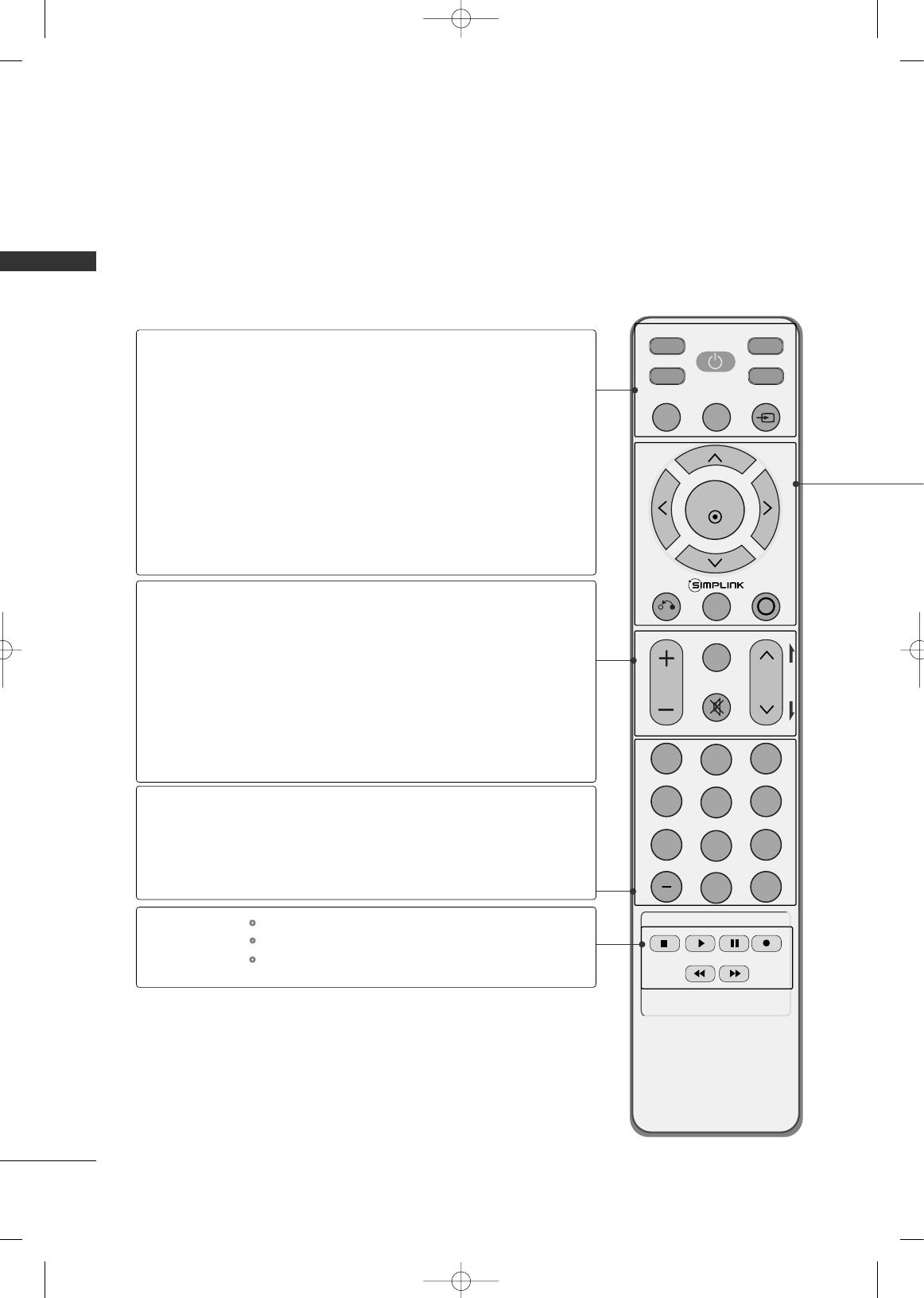
REMOTE CONTROL FUNCTIONS
PREPARATION
When using the remote control, aim it at the remote control sensor on the TV.
INPUT
FAV
MUTE
TV
STB
POWER
Q. MENU MENU
AV MODERETURN
ENTER
VOL
CH
123
456
78
0
9
FLASHBK
P
A
G
E
DVD
VCR
TV/STB/DVD/VCR
POWER
Q.MENU
MENU
INPUT
VOLUME UP
/DOWN
FAV
MUTE
CHANNEL
UP/DOWN
PAGE
UP/DOWN
— (DASH)
FLASHBK
Select the remote operating mode: TV, STB, DVD, or VCR.
Turns your TV or any other programmed equipment on or
off, depending on the mode.
Select the desired quick menu source.
Displays the main menu.
Clear all on-screen displays and return to TV viewing from
any menu.
External input modes rotate in regular sequence.
Increase/decrease the sound level.
Scroll through the programmed Favorite channels.
Switch the sound on or off.
Select available channels.
Move from one full set of screen information to the next one.
Used to enter a program number for multiple
program channels such as 2-1, 2-2, etc.
Tune to the last channel viewed.
Control video cassette recorders or DVD players.
Control USB menu (PHOTO LIST and MUSIC LIST.)
Control the SIMPLINK compatible devices.
NUMBER button
VCR/DVD, USB,
SIMPLINK
Control buttons
MFL34797048-en-4 3/18/08 7:27 PM Page 10
PREPARATION
11
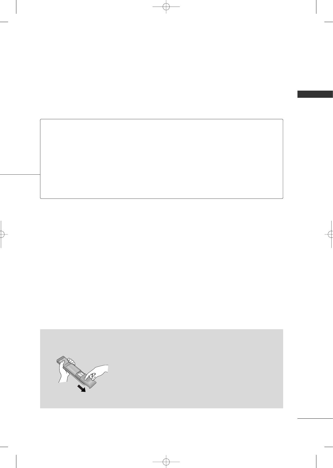
Installing Batteries
■
Open the battery compartment cover on the back side and install
the batteries matching correct polarity
(
+with +,-with -
)
.
■
Install two 1.5V AAA batteries. Don’t mix old or used batteries with
new ones.
■
Close cover.
THUMBSTICK
(Up/Down/Left
Right/ENTER)
RETURN
SIMPLINK
AV MODE
Navigate the on-screen menus and adjust the system settings to your preference.
Allows the user to move return one step in an interactive application or other user interaction
function.
See a list of AV devices connected to TV.
When you toggle this button, the SIMPLINK menu appears at the screen.
It helps you select and set images and sounds.
MFL34797048-en-4 3/18/08 7:27 PM Page 11

PREPARATION
12
STAND INSTALLATION
PREPARATION
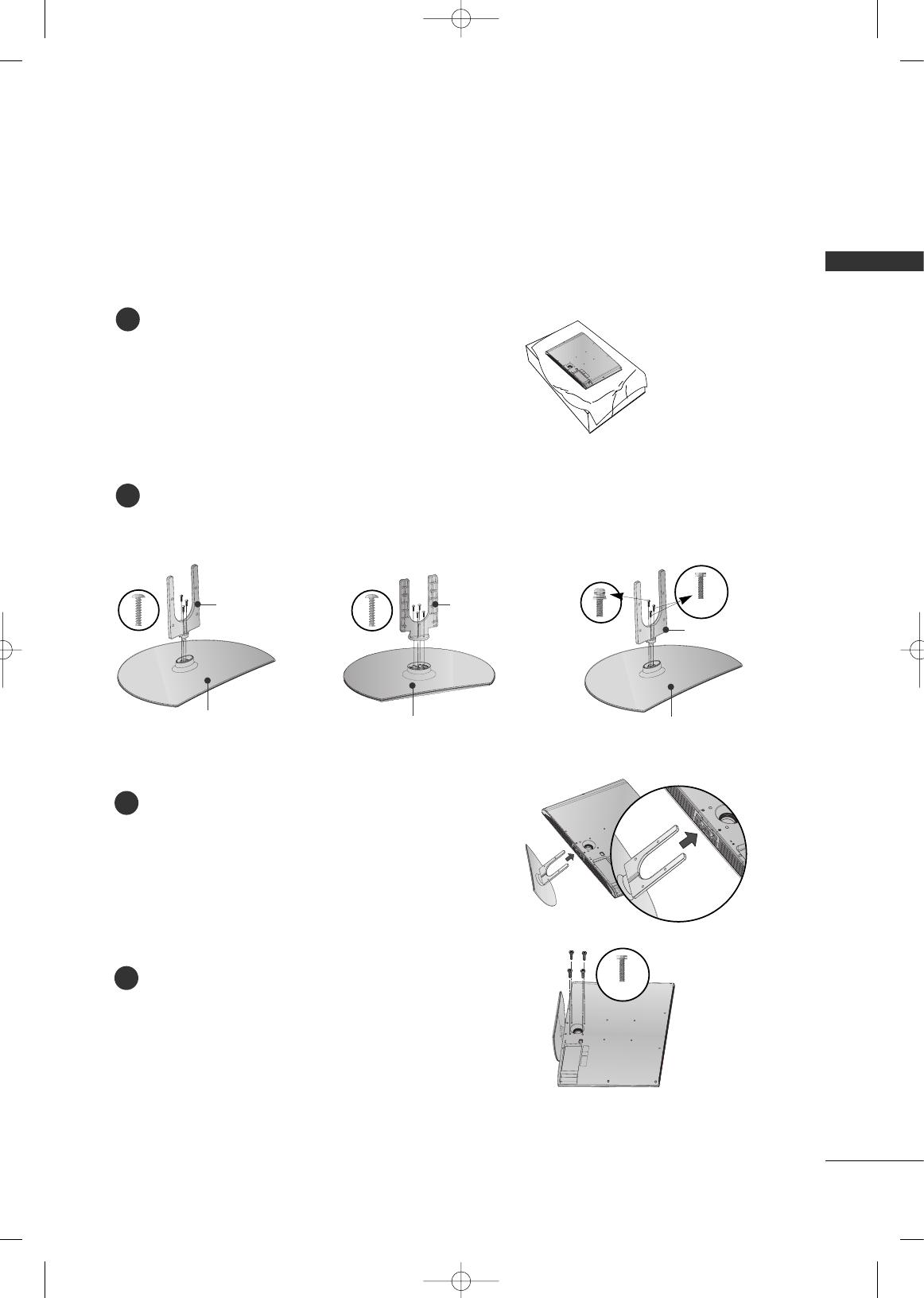
■
Image shown may differ from your TV
Carefully place the TV screen side down on a
cushioned surface to protect the screen from
damage.
Assemble the TV as shown.
Fix the 4 bolts securely using the holes in the
back of the TV.
1
2
Assemble the parts of the
SSTTAANNDD BBOODDYY
with
CCOOVVEERR BBAASSEE
of the TV.
2
3
Assemble the TV as shown.
3
Fix the 4 bolts securely using the holes in the
back of the TV.
4
Only 42PG25 Only 32/37/42LG30, 37/42LG50, 32/42LG70
SSTTAANNDD BBOODDYY
CCOOVVEERR BBAASSEE
Carefully place the TV screen side down on a
cushioned surface to protect the screen from
damage.
1
MFL34797048-en-4 3/18/08 7:27 PM Page 12
PREPARATION
13
Assemble the parts of the
SSTTAANNDD BBOODDYY
with
CCOOVVEERR BBAASSEE
of the TV.
2
Assemble the TV as shown.
3
Fix the 4 bolts securely using the holes in the
back of the TV.
4
Only 32/37/42LG60
Carefully place the TV screen side down on a
cushioned surface to protect the screen from
damage.
1
32LG60 37LG60 42LG60
(M4x16)
SSTTAANNDD BBOODDYY SSTTAANNDD BBOODDYY
CCOOVVEERR BBAASSEE
SSTTAANNDD BBOODDYY
CCOOVVEERR BBAASSEE
CCOOVVEERR BBAASSEE
(M4x20)
MFL34797048-en-4 3/18/08 7:27 PM Page 13
PREPARATION
14
PREPARATIONPREPARATION
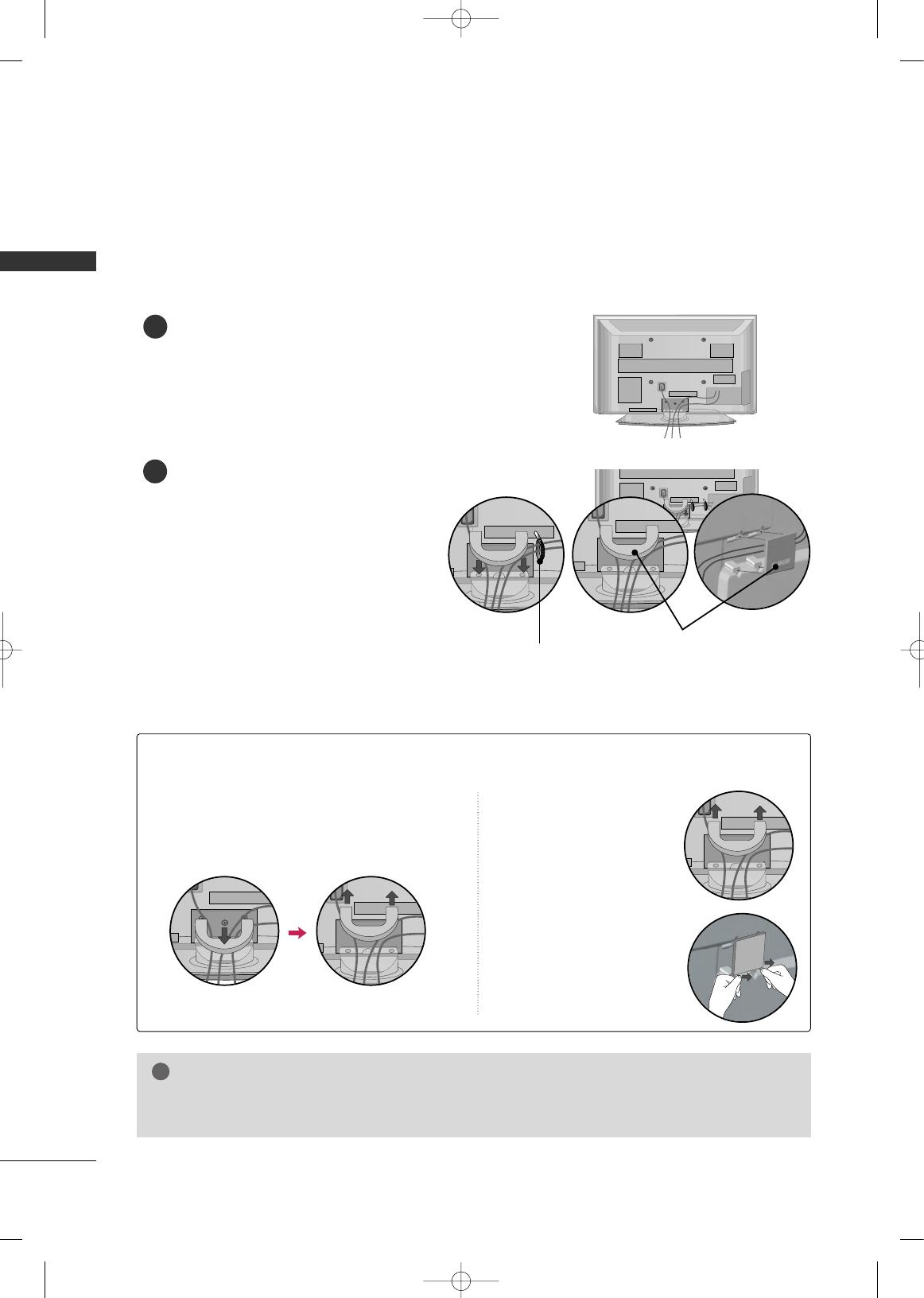
CABLE MANAGEMENT
Plasma TV Model
Connect the cables as necessary.
To connect additional equipment, see the
EXTERNAL EQUIPMENT SETUP section.
Install the CABLE MANAGEMENT CLIP as
shown.
If your TV has the CABLE HOLDER, install it
as shown and bundle the cables.
1
2
■
Here shown may be somewhat different from your TV.
GG
Do not hold the CABLE MANAGEMENT CLIP when moving the TV.
- If the TV is dropped, you may be injured or the product may be broken.
NOTE
!
How to remove the CABLE MANAGEMENT CLIP
GG
First, press the cable management. Hold the
CCAABBLLEE MMAANNAAGGEEMMEENNTT CCLLIIPP
with both
hands and pull it upward.
GG
Separate
CCAABBLLEE MMAANN--
AAGGEEMMEENNTT CCLLIIPP
from TV
by pressing two latches.
GG
Hold the CABLE MAN-
AGEMENT CLIP with both
hands and pull it upward.
42PG25
50PG25, 50/60PG60
CABLE MANAGEMENT CLIP
CABLE HOLDER
MFL34797048-en-4 3/18/08 7:27 PM Page 14
PREPARATION
15
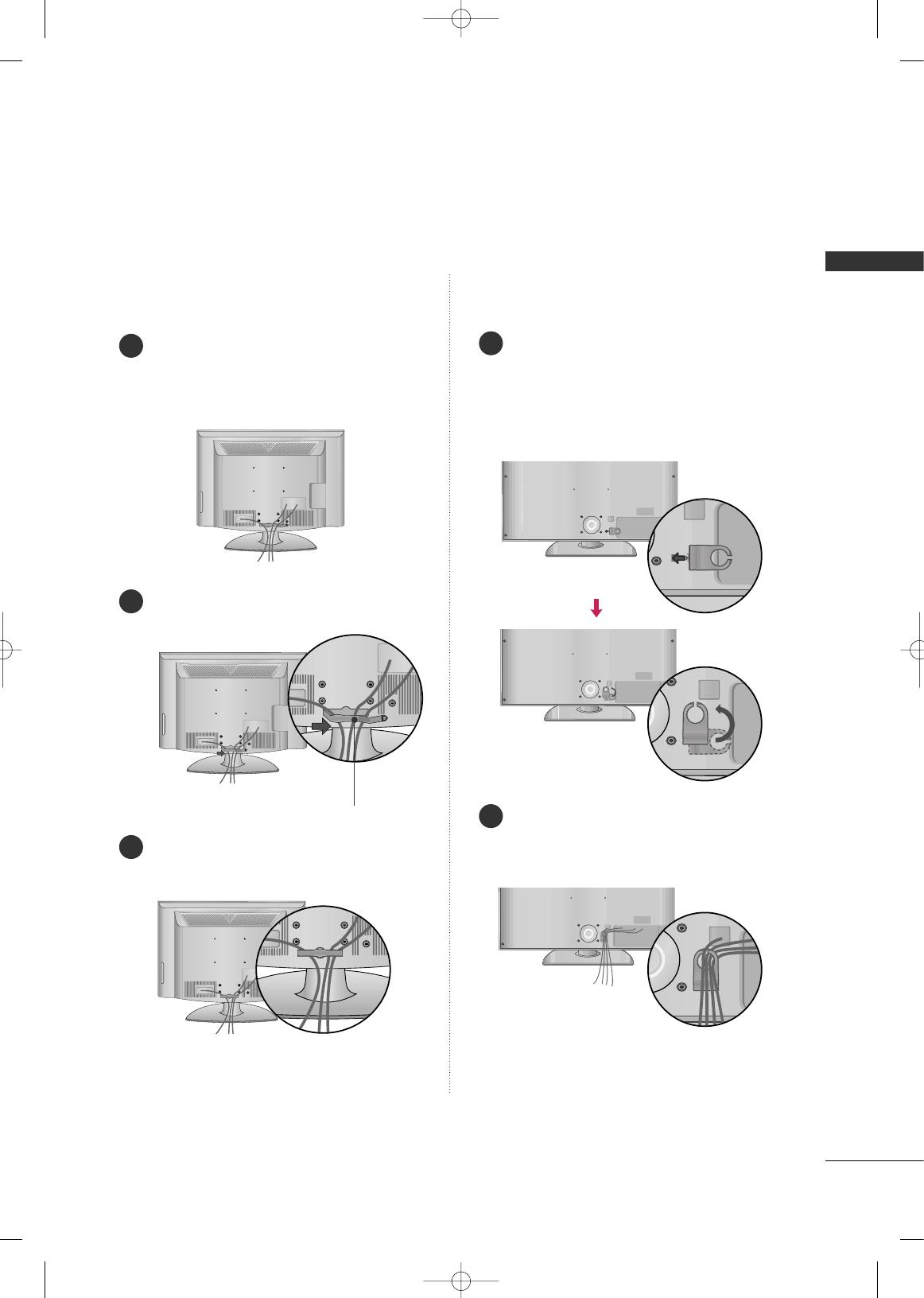
LCD TV Model
Connect the cables as necessary.
To connect additional equipment, see the
EXTERNAL EQUIPMENT SETUP section.
Install the CABLE MANAGEMENT CLIP as
shown.
CABLE MANAGEMENT CLIP
Align the hole with the tab on the
CCAABBLLEE
MMAANNAAGGEEMMEENNTT CCLLIIPP
.
Turn the
CCAABBLLEE MMAANNAAGGEEMMEENNTT CCLLIIPP
as
shown.
Note: This cable management can be broken
by excessive pressure.
Connect the cables as necessary.
To connect additional equipment, see the
EXTERNAL EQUIPMENT SETUP section.
Put the cables inside the CABLE MANAGEMENT
CLIP and snap it closed.
32/37/42/47/52LG6032/37/42LG30, 37/42/47/52LG50,
32/42/47/52LG70
1
2
3
1
2
MFL34797048-en-4 3/18/08 7:27 PM Page 15
PREPARATION
16
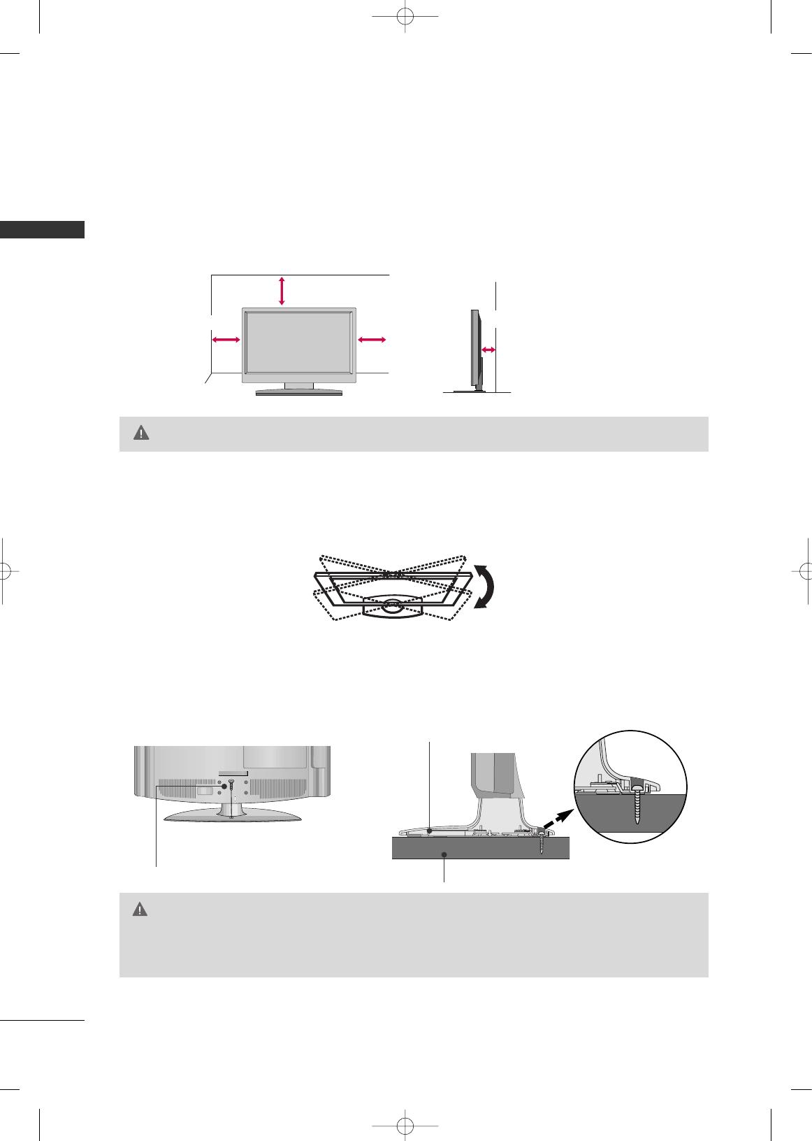
DESKTOP PEDESTAL INSTALLATION
PREPARATION
For proper ventilation, allow a clearance of 4 inches on all four sides from the wall.
■
Image shown may differ from your TV.
4 inches
4 inches
4 inches
4 inches
SWIVEL STAND
After installing the TV, you can adjust the TV set manually to the left or right direction by 20 degrees to suit
your viewing position.
GG
Ensure adequate ventilation by following the clearance recommendations.
CAUTION
ATTACHING THE TV TO A DESK (Only 32LG30/70)
The TV must be attached to a desk so it cannot be pulled in a forward/backward direction, potentially causing
injury or damaging the product.
GG
To prevent TV from falling over, the TV should be securely attached to the floor/wall per installation
instructions. Tipping, shaking, or rocking the machine may cause injury.
WARNING
1-Screw
(provided as parts of the product)
Desk
Stand
MFL34797048-en-4 3/18/08 7:27 PM Page 16
PREPARATION
17
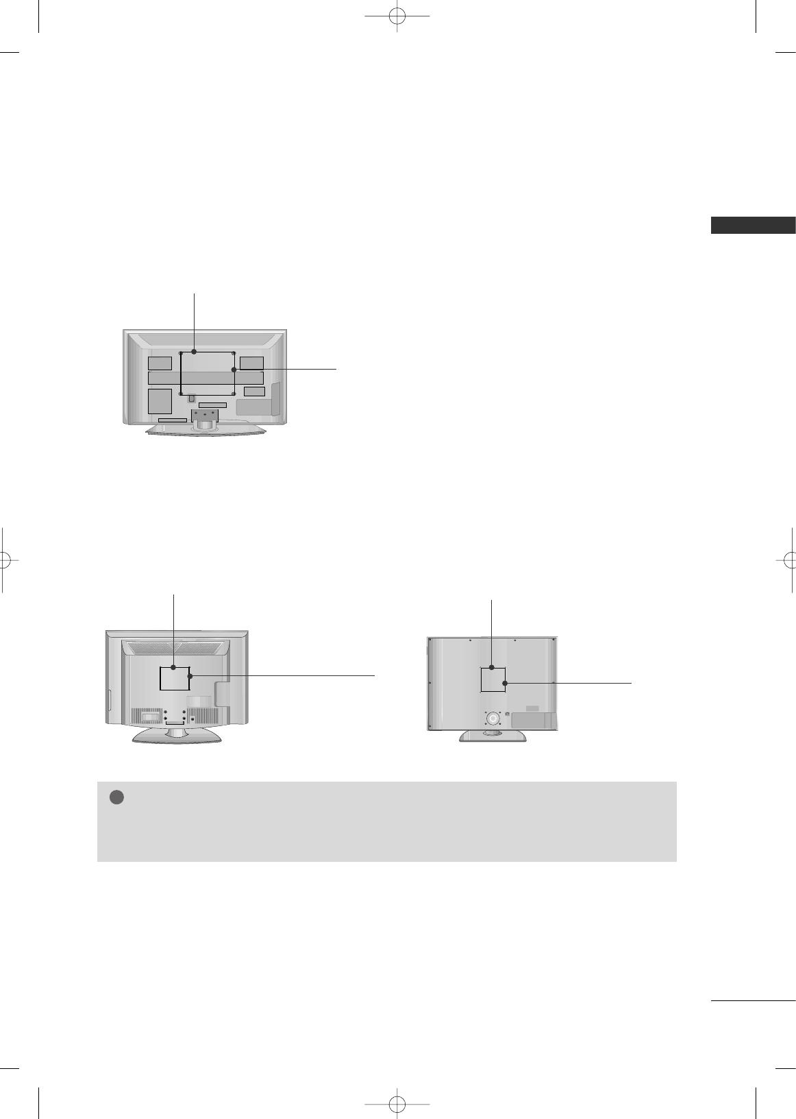
VESA WALL MOUNTING
This TV accepts VESA FDMI compliant mounts via the four screw holes on the back of the TV.
We recommend that you use a wall mounting bracket of LG brand when mounting the TV to a wall.
GG
Screw length needed depends on the wall mount used. For further information, refer to the instructions
included with the mount.
NOTE
!
Plasma TV Models
LCD TV Models
R
( )
R
( )
400 mm
(Except 60PG60: 600 mm)
400 mm
200 mm
(Except 52LG50/70: 800 mm)
32LG30/70: 100 mm
37LG30/50: 200 mm
42LG30/50/70: 200 mm
47LG50/70: 200 mm
52LG50/70: 400 mm
R
200 mm
(Except 52LG60: 800 mm)
32LG60: 100 mm
37/42/47LG60: 200 mm
52LG60: 400 mm
32/37/42LG30, 37/42/47/52LG50,
32/42/47/52LG70
32/37/42/47/52LG60
MFL34797048-en-4 3/18/08 7:27 PM Page 17
PREPARATION
18
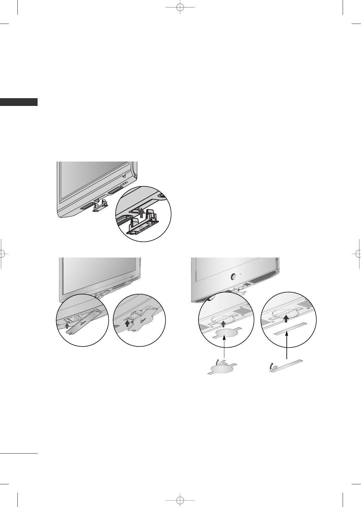
PROTECTION COVER
PREPARATION
■
Image shown may differ from your TV.
Plasma TV Models
LCD TV Models
You can remove the stand before installing the TV on a wall mount by performing the previous stand instructions
in reverse. After removing the stand, install the included
pprrootteeccttiioonn ccoovveerr
over the hole for the stand.
Insert the
PPRROOTTEECCTTIIOONN CCOOVVEERR
into the TV until clicking sound.
After removing the protection paper from the
protection cover, adhere it to the TV as shown.
MFL34797048-en-4 3/18/08 7:27 PM Page 18
PREPARATION
19
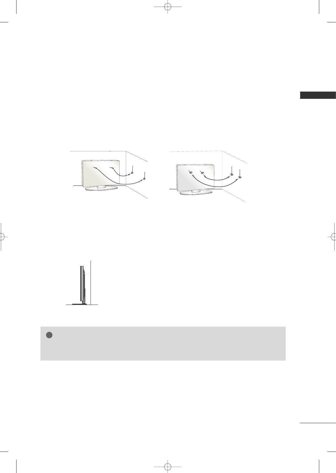
SECURING THE TV TO THE WALL TO PREVENT FALLING
We recommend that you set up the TV close to a wall so it cannot fall over if pushed backwards.
Additionally, we recommend that the TV be attached to a wall so it cannot be pulled in a forward direction,
potentially causing injury or damaging the product.
Caution: Please make sure that children don’t climb on or hang from the TV.
■
Insert the eye-bolts (or TV brackets and bolts) to tighten the product to the wall as shown in the picture.
*If your product has the bolts in the eye-bolts position before inserting the eye-bolts, loosen the bolts.
* Insert the eye-bolts or TV brackets/bolts and tighten them securely in the upper holes.
Secure the wall brackets with the bolts (not provided as parts of the product, must purchase separately) to
the wall. Match the height of the bracket that is mounted on the wall to the holes in the product.
Ensure the eye-bolts or brackets are tightened securely.
■
Use a sturdy rope (not provided as parts of the product, must pur-
chase separately) to tie the product. It is safer to tie the rope so it
becomes horizontal between the wall and the product.
■
You should purchase necessary components to prevent TV from falling off of the stand.
■
Image shown may differ from your TV.
GG
Use a platform or cabinet strong enough and large enough to support the size and weight of the TV.
GG
To use the TV safely make sure that the height of the bracket on the wall and the one on the TV are the same.
NOTE
!
MFL34797048-en-4 3/18/08 7:27 PM Page 19

PREPARATION
20
ANTENNA OR CABLE CONNECTION
PREPARATION
1. Antenna (Analog or Digital)
Wall Antenna Socket or Outdoor Antenna without a Cable Box
Connection.
For optimum picture quality, adjust antenna direction if needed.
2. Cable
Wall
Antenna
Socket
Outdoor
Antenna
(VHF, UHF)
Cable TV
Wall Jack
Multi-family Dwellings/Apartments
(Connect to wall antenna socket)
RF Coaxial Wire (75 ohm)
RF Coaxial Wire (75 ohm)
Single-family Dwellings /Houses
(Connect to wall jack for outdoor antenna)
Be careful not to bend the copper wire
when connecting the antenna.
Copper Wire
GG
The TV will let you know when the analog, cable, and digital channel scans are complete.
NOTE
!
■
To improve the picture quality in a poor signal area, please purchase a signal amplifier and install properly.
■
If the antenna needs to be split for two TV’s, install a 2-Way Signal Splitter.
■
If the antenna is not installed properly, contact your dealer for assistance.
Antenna
UHF
Signal
Amplifier
VHF
ANTENNA/
CABLE IN
( )
R
ANTENNA/
CABLE IN
( )
R
ANTENNA/
CABLE IN
( )
R
■
To prevent damage do not connect to the power outlet until all connections are made between the devices.
MFL34797048-en-4 3/18/08 7:27 PM Page 20
/