1
! IMPORTANT SAFETY INSTRUCTIONS !
This symbol indicates that there are important
operating and maintenance instructions in the
literature accompanying this unit.
This symbol indicates that dangerous
voltage constituting a risk of electric shock
is present within this unit.
1. READ these instructions.
2. KEEP these instructions.
3. HEED all warnings.
4. FOLLOW all instructions.
5. DO NOT use this apparatus near water. DO NOT
expose the apparatus to dripping and splashing.
DO NOT put objects filled with liquids, such as
vases, on the apparatus.
6. CLEAN ONLY with a dry cloth.
7. DO NOT block any of the ventilation openings.
Install in accordance with the manufacturer’s in-
structions.
8. Do not install near any heat sources such as radia-
tors, heat registers, stoves, or other apparatus (in-
cluding amplifiers) that produce heat.
9. DO NOT defeat the safety purpose of the ground-
ing-type plug. The third prong is provided for your
safety. When the provided plug does not fit into
your outlet, consult an electrician for replacement
of the obsolete outlet.
10. PREVENT the power cord from being walked on or
pinched, especially at plugs, receptacles, and the
point of exit from the apparatus.
11. USE only attachments/accessories specified by
the manufacturer.
12. USE only with a cart, stand, tripod,
bracket, or table specified by the
manufacturer or sold with the
apparatus. When a cart is used, use
caution when moving the cart-appa-
ratus combination to avoid injury
from tip-over.
13. UNPLUG this apparatus during lightning storms or
when unused for long periods of time.
14. REFER all servicing to qualified service person-
nel. Servicing is required when the apparatus has
been damaged in any way, such as when the pow-
er-supply cord or plug has been damaged, liquid
has been spilled or objects have fallen into the ap-
paratus, the apparatus has been exposed to rain
or moisture, does not operate normally, or has
been dropped.
15. DO NOT expose the apparatus to dripping and
splashing. DO NOT put objects filled with liquids,
such as vases, on the apparatus.
WARNING: Voltages in this equipment are hazardous to life. No user-serviceable parts inside. Refer all servicing
to qualified service personnel. The safety certifications do not apply when the operating voltage is changed from the
factory setting.
27C8571 (Rev. 6)
2004, Shure Incorporated
Printed in U.S.A.

ENGLISH
2
TABLE OF CONTENTS
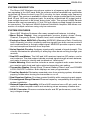
SYSTEM DESCRIPTION 3. . . . . . . . . . . . . . . . . . . . . . . . . . . . . . . . . . . . . . . . . . . . . . . . . . . . . . . .
SYSTEM FEATURES 3. . . . . . . . . . . . . . . . . . . . . . . . . . . . . . . . . . . . . . . . . . . . . . . . . . . . . . . . . . .
SYSTEM COMPONENTS 4. . . . . . . . . . . . . . . . . . . . . . . . . . . . . . . . . . . . . . . . . . . . . . . . . . . . . . .
U1 BODY-PACK TRANSMITTER CONTROLS & INDICATORS 5. . . . . . . . . . . . . . . . . . . . . . .
U2 MICROPHONE-TRANSMITTER CONTROLS & INDICATORS 6. . . . . . . . . . . . . . . . . . . . . .
U4S & U4D RECEIVER CONTROLS & CONNECTORS 7. . . . . . . . . . . . . . . . . . . . . . . . . . . .
RECEIVER SETUP 9. . . . . . . . . . . . . . . . . . . . . . . . . . . . . . . . . . . . . . . . . . . . . . . . . . . . . . . . . . . . .
Installing Rear Mounted Receiver Antennas 9. . . . . . . . . . . . . . . . . . . . . . . . . . . . . . . . . . . . . . .
Installing Front Mounted Receiver Antennas 9. . . . . . . . . . . . . . . . . . . . . . . . . . . . . . . . . . . . . .
Basic Receiver Connections 11. . . . . . . . . . . . . . . . . . . . . . . . . . . . . . . . . . . . . . . . . . . . . . . . . .
VIEWING CURRENT RECEIVER SETTINGS 12. . . . . . . . . . . . . . . . . . . . . . . . . . . . . . . . . . . . . .
PROGRAMMING THE RECEIVER 12. . . . . . . . . . . . . . . . . . . . . . . . . . . . . . . . . . . . . . . . . . . . . . .
Changing Receiver Group/Channel Settings 12. . . . . . . . . . . . . . . . . . . . . . . . . . . . . . . . . . . . .
Changing Receiver Frequency Setting 14. . . . . . . . . . . . . . . . . . . . . . . . . . . . . . . . . . . . . . . . . .
Changing Receiver Name 15. . . . . . . . . . . . . . . . . . . . . . . . . . . . . . . . . . . . . . . . . . . . . . . . . . . . .
Changing Receiver Squelch Level Setting 16. . . . . . . . . . . . . . . . . . . . . . . . . . . . . . . . . . . . . . .
Locking the Receiver Display 18. . . . . . . . . . . . . . . . . . . . . . . . . . . . . . . . . . . . . . . . . . . . . . . . .
Unlocking the Receiver Display 19. . . . . . . . . . . . . . . . . . . . . . . . . . . . . . . . . . . . . . . . . . . . . . .
TRANSMITTER SETUP 20. . . . . . . . . . . . . . . . . . . . . . . . . . . . . . . . . . . . . . . . . . . . . . . . . . . . . . . .
Transmitter Battery Installation 20. . . . . . . . . . . . . . . . . . . . . . . . . . . . . . . . . . . . . . . . . . . . . . . . .
Checking Transmitter Batteries 21. . . . . . . . . . . . . . . . . . . . . . . . . . . . . . . . . . . . . . . . . . . . . . . .
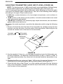
Connecting a Lavalier Microphone or Instrument Cable to the
U1 Transmitter 22. . . . . . . . . . . . . . . . . . . . . . . . . . . . . . . . . . . . . . . . . . . . . . . . . . . . . . . . . . . . .
PROGRAMMING THE TRANSMITTER 22. . . . . . . . . . . . . . . . . . . . . . . . . . . . . . . . . . . . . . . . . . .
Changing Transmitter Group/Channel Settings 22. . . . . . . . . . . . . . . . . . . . . . . . . . . . . . . . . . .
Locking the Power Switch in the ON Position 25. . . . . . . . . . . . . . . . . . . . . . . . . . . . . . . . . . . . .
Cancelling the Power On Lock Function 25. . . . . . . . . . . . . . . . . . . . . . . . . . . . . . . . . . . . . . . . .
Activating the Frequency Lock Function 26. . . . . . . . . . . . . . . . . . . . . . . . . . . . . . . . . . . . . . . . .
Cancelling the Frequency Lock Function 27. . . . . . . . . . . . . . . . . . . . . . . . . . . . . . . . . . . . . . . .
OPERATING THE U1 BODY–PACK SYSTEM 27. . . . . . . . . . . . . . . . . . . . . . . . . . . . . . . . . . . . .
OPERATING THE U2 HAND-HELD SYSTEM 28. . . . . . . . . . . . . . . . . . . . . . . . . . . . . . . . . . . . .
ADJUSTING TRANSMITTER AUDIO GAIN LEVEL 29. . . . . . . . . . . . . . . . . . . . . . . . . . . . . . . . .
ADJUSTING TRANSMITTER AUDIO INPUT LEVEL 30. . . . . . . . . . . . . . . . . . . . . . . . . . . . . . . .
TIPS FOR ACHIEVING OPTIMUM PERFORMANCE 31. . . . . . . . . . . . . . . . . . . . . . . . . . . . . . . .
TROUBLESHOOTING 31. . . . . . . . . . . . . . . . . . . . . . . . . . . . . . . . . . . . . . . . . . . . . . . . . . . . . . .
SPECIFICATIONS 32. . . . . . . . . . . . . . . . . . . . . . . . . . . . . . . . . . . . . . . . . . . . . . . . . . . . . . . . . . . . .
LICENSING INFORMATION 32. . . . . . . . . . . . . . . . . . . . . . . . . . . . . . . . . . . . . . . . . . . . . . . . . . . .
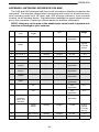
APPENDIX: NETWORK INTERFACE PIN MAP 33. . . . . . . . . . . . . . . . . . . . . . . . . . . . . . . . . . . .

ENGLISH
3
SYSTEM DESCRIPTION
The Shure UHF Wireless microphone system is a frequency-agile diversity sys-
tem operating in the UHF band. Both the receiver and the transmitter are synthesizer
controlled via Phase Locked Loop (PLL) circuitry for clear, steady radio frequency
(RF) signal. The receiver is available in either dual or single models that fit into a stan-
dard 19 inch (482 mm) equipment rack. An auxiliary unswitched AC output jack al-
lows multiple receivers to be linked “daisy chain” style. The optional UA830 Remote
Antenna Kits can be powered by 12 Vdc, 500 mA output provided through the anten-
na connectors. The optional UA845 Antenna Distribution Amplifier Kits allows con-
nection of multiple receivers using only two antennas.
SYSTEM FEATURES
Shure UHF Wireless Systems offer many exceptional features, including:
• Menu Driven Display. User–programmable receiver display shows Group,
Channel, Frequency, Name, Squelch level, and Locked/Unlocked status.
• Exclusive Shure MARCAD
Circuitry. MARCAD (Maximum Ratio Combining
Audio Diversity) circuitry constantly monitors signals from both receiver sections
and combines them in a single output signal. MARCAD provides superior recep-
tion and exceptional freedom from dropouts.
• Noise Squelch Circuitry. Analyzes signal quality instead of signal strength. This
virtually eliminates the possibility of annoying noise bursts coming through your
receiver.
• Dual RF Level Meters. The U4S and U4D receivers have two RF meters, one for
each antenna. The dual meters indicate received signal strength at each antenna,
and make it easier to identify and troubleshoot “dead spots”.
• Audio Metering. Each receiver includes a seven–segment audio meter that lets
you monitor audio level and helps optimize transmitter gain setting.
• Transmitter Display. Shows Group, Channel, Battery Power Level, and POWER
LOCK ON/OFF* condition. Both displays are user programmable.
• Tone Key Squelch: Eliminates unwanted noise from entering system; eliminates
popping noises when turning the transmitter on or off.
• Dual Receiver Option: Provides greater flexibility while conserving rack space.
• Preconfigured Group/Channel: Ensures frequency compatibility and simplifies
system installation.
• Network Expansion Capability. U4S and U4D receivers have a 25–pin serial con-
nector for future computer control and monitoring via an accessory interface box.
• DC/DC Converter: Ensures consistent audio and RF performance, even if bat-
tery voltages change.
* U.S. Patent No. 5,692,057.

ENGLISH
4
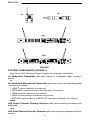
FIGURE 1
U1
U2
U4S
U4D
SYSTEM COMPONENTS (FIGURE 1)
Each Shure UHF Wireless System includes the following components:
U1 Body-Pack Transmitter with your choice of instrument cable or micro-
phone,
or
U2 Hand-Held Microphone-Transmitter with your choice of interchangeable
microphone heads:
• SM58
cardioid dynamic microphone
• BETA 58A
supercardioid premium dynamic microphone
• SM86 cardioid condenser microphone
• SM87A supercardioid condenser microphone
• BETA 87A supercardioid or BETA 87C premium condenser microphone;
and a
U4S Single Channel Diversity Receiver with rack-mounting hardware and
antennas,
or a
U4D Dual Channel Diversity Receiver with rack-mounting hardware and an-
tennas.

ENGLISH
5
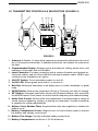
U1 TRANSMITTER CONTROLS & INDICATORS (FIGURE 2)
ON
FIGURE 2
OFF
a
b
cde
f
g
h
i
j
k
l
m
a
1. Antenna: A flexible 1/4 wave whip antenna is permanently attached to the top of
the U1 body-pack transmitter. A qualified technician can replace the antenna in
the field.
2. Programmable Display: Displays group and channel, battery power level, and
frequency lock/power lock on/off status.
3. Input Connector: Provides connection with a variety of lavalier and headset mi-
crophone cables, and the Shure WA302 instrument adapter cable. LEMO–type
connectors are available as an option.
4. ON/OFF Switch: Turns transmitter power on and off.
5. On/Off LED: Glows green when the U1 is turned on.
6. Belt Clip: Allows the transmitter to be easily worn on a belt, waistband, or guitar
strap.
7. MODE Button: Selects the parameter (Group or Channel) you wish to change.
8. SET Button: Changes transmitter Group and Channel settings. Also used with
the MODE button to lock power on and to lock the frequency and channel setting.
9. Audio Gain Control: Allows audio level adjustment to accommodate a variety of
sound sources (speaking, singing, or playing an instrument). A small screwdriver
is supplied for making adjustments.
10. Battery Cover Release Tabs: Squeeze these two tabs together to release the
battery cover.
11. Battery Compartment Cover: Hinged cover on front surface opens to expose
the battery and display control keys.
12. Battery Fuel Gauge: Visually indicates battery power level.
13. Battery Compartment: Holds two 1.5V AA batteries.

ENGLISH
6
ON
OFF
FIGURE 3
GAIN
d
e
a
b
c
g
hi
j
f
U2 TRANSMITTER CONTROLS & INDICATORS (FIGURE 3)
1. Grille: Protects the microphone cartridge and helps reduce breath sounds and wind
noise. The grilles for the various microphone heads differ in appearance.
2. Programmable Display: Displays Group and Channel, battery power level, and
frequency lock/power lock on/off status.
3. Battery Fuel Gage: Visually indicates battery power level.
4. Battery Cover: Unscrews to expose batteries and display control keys.
5. ON/OFF Switch: Turns transmitter power on and off.
6. Antenna: Helical antenna is attached to the end of the U2 transmitter. A qualified
technician can replace the antenna in the field.
7. Battery Compartment: Holds two 1.5 V AA batteries.
8. MODE Button: Selects the parameter (Group or Channel) you wish to change.
9. SET Button: Changes transmitter Group and Channel settings. Also used with
the MODE button to lock power on and to lock the frequency and channel setting.
10. Audio Gain Control: Allows audio level adjustment to accommodate a variety of
sound sources (speaking, singing, or playing an instrument). A small screwdriver
is supplied for making adjustments.

ENGLISH
7
FIGURE 4
U4S Receiver
U4D Receiver
mn o pqr s
adbc e f gh ij k l
o
mn o pqr s
adbc e f g h ij k
l
abcdefg
h
opq r
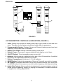
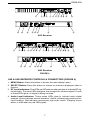
U4S & U4D RECEIVER CONTROLS & CONNECTORS (FIGURE 4)
1. MENU Button: Press this button to access the main display menu.
2. SELECT Button: Press this button to choose or execute a displayed value or
function.
3. RF Level Indicators: Five LEDs per RF antenna channel glow to indicate RF sig-
nal strength. The more LEDs that glow, the stronger the received signal. If none
of these LEDs glow, no signal is being received.
4. Audio Level Indicators: These seven LEDs glow to indicate audio signal
strength. Green indicates normal operation. Amber indicates approaching over-
load condition. Red indicates excessively high audio levels. (Clipping occurs
within 4–6 dB when the red LEDs glow).

ENGLISH
8
5. Programmable Display: Displays group and channel number, frequency,
squelch level, system name, transmitter battery power level, and display lock on/
off status.
6. + Button: Press this button to scroll display forward.
7. – Button: Press this button to scroll display backward.
8. Audio Output Control: Adjusts receiver output level to match input level require-
ments of a mixer or amplifier. Normally, this control is set fully clockwise.
9. Headphone Monitor Volume Control: Rotate this knob to the right to increase
headphone volume; rotate it to the left to decrease headphone volume.
NOTE: If you are using a Model U4S Receiver, press the Headphone Volume
Control knob to turn the monitor on or off.
If you are using a Model U4D Receiver, press the Headphone Volume Control
knob once to select Receiver 1 or twice to select Receiver 2, depending on which
section you wish to monitor.
10. Headphone Monitor Status: These LEDs glow yellow when the headphone
monitor circuit is turned on or off.
NOTE: The Tone Key feature is present only on the receiver output. As a result,
you may hear an occasional “pop” through the headphones when the transmitter
is turned on or off.
11. Headphone Input Connector: Plug headphones into this 1/4–inch connector to
monitor receiver audio.
12. POWER On/Off Switch: Turns the receiver on and off.
13. Power Input Connector: Accepts power directly from any 90 to 230 VAC, 50/60
Hz power source.
14. Power Output Connector: Provides 90 to 230 VAC, 50/60 Hz power to additional
equipment. It can be used to link multiple receivers or to power the Shure UA840
Antenna Distribution System.
15. Antenna Input Connectors: BNC-type connectors provide connection to the
supplied antennas or to coaxial cable used with a distribution amplifier or remote
antennas.
CAUTION: To avoid damage to equipment, make sure any equipment connected
to the antenna inputs can tolerate 12 VDC power.
16. HIGH Z (Unbalanced) Output Connector: 1/4 inch phone jack provides unbal-
anced auxiliary level (high-impedance) output.
17. Mic/Line Slide Switch: Controls output of balanced XLR connector. It can be set
for microphone or line-level (microphone level = line level – 30 dB).
18. LOW Z (Balanced) Output Connector: XLR connector provides balanced low-
impedance mic level or line-level output.
19. Networking Interface: 25–pin “D” connector provides future electronic interface
to computers and other equipment via accessory interface box.

ENGLISH
9
RECEIVER SETUP
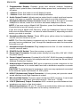
Installing Rear Mounted Receiver Antennas
Attach the supplied UHF antennas to the antenna BNC connectors on the receiver
back panel, as shown in Figure 5. For best performance, orient the antennas with tips
pointing away from each other at a 45° angle from vertical.
FIGURE 5
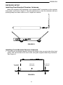
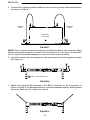
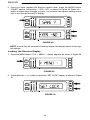
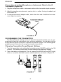
Installing Front Mounted Receiver Antennas
1. Insert the two bulkhead adapters through the larger holes on each side of the front
panel, and secure them from each side, using the supplied attaching hardware.
See Figure 6.
RECEIVER
(TOP VIEW)
FIGURE 6
BULKHEAD
ADAPTER
BULKHEAD
ADAPTER

ENGLISH
10
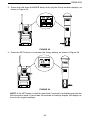
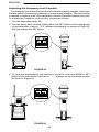
2. Connect the supplied antenna cables to the receiver and the bulkhead adapters,
as shown in Figure 7.
RECEIVER
(TOP VIEW)
FIGURE 7
ANTENNA
CABLE
ANTENNA
CABLE
NOTE: Shure recommends connecting the bulkhead adapter and antenna cables
before mounting the receiver in a rack. Once the receiver is in the rack, it is more diffi-
cult to insert the bulkhead adapters and connect the antenna cables.
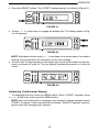
3. Insert the receiver into the equipment rack and secure it with the supplied screws.
See Figure 8.
EQUIPMENT RACK
FIGURE 8
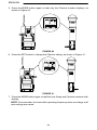
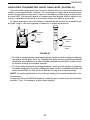
4. Attach the supplied UHF antennas to the BNC connectors on the front panel, as
shown in Figure 9. For best performance, orient the antennas with tips pointing away
from each other at a 45° angle from vertical.
FIGURE 9

ENGLISH
11
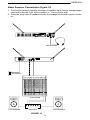
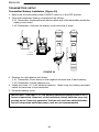
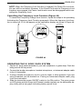
Basic Receiver Connections (Figure 10)
1. Connect the receiver output to the mixer or amplifier input, using a standard audio
cable with a female 3-pin XLR connector or
1
/
4
-inch phone plug.
2. If desired, plug a set of headphones into the headphone monitor output connec-
tor.
AC POWER
FIGURE 10
AUDIO MIXER
AMPLIFIER LOUDSPEAKERLOUDSPEAKER
HEADPHONES

ENGLISH
12
3. Connect the female end of a modular power cord to the male power input connec-
tor on the rear panel of the receiver. Then plug the power cord into a suitable AC
power source.
NOTE: If the receiver is rack-mounted, or if using front–mounted antennas, the
antennas should extend above the rack cabinet or be remotely located. Improved
diversity performance may be obtained by installing one or both antennas at a
remote location and separating them by 1.5 meters (60 inches) or more. Anten-
nas at remote locations should be connected to the receiver via UA825 or UA850
Extension Cable Kit(s) or other suitable low-loss cable (RG8 or equivalent) and
used in conjunction with a UA830 Active Remote Antenna Kit.
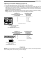
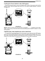
VIEWING CURRENT RECEIVER SETTINGS
To view current settings on the receiver display, proceed as follows:
1. Turn the receiver on by pressing upper half of the POWER switch.
2. Press either the “+” button or the “–” button on the receiver front panel to scroll
through the current settings.
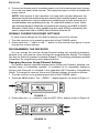
PROGRAMMING THE RECEIVER
You can change the receiver Group/Channel setting, the operating frequency,
squelch level, and receiver name through the programmable display. The display
can then be locked to prevent accidental changes. The following paragraphs present
instructions for programming each display function.
Changing Receiver Group/Channel Settings
The receiver display identifies frequencies by Group and Channel, allowing con-
venient setup of compatible systems. A complete list of compatible frequency
Groups and Channels is included in the separate UHF Frequency Compatibility
Guide. To change the receiver Group and Channel settings, proceed as follows:
1. Turn the receiver on by pressing upper half of the POWER switch.
2. Press the MENU button. The “+ MENU –” display appears, as shown in Figure 11.
FIGURE 11
3. Press either the + or – button to reach the SET G/CH display, shown in Figure 12.
FIGURE 12

ENGLISH
13
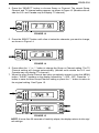
4. Press the “SELECT” button to choose Group or Channel. The current Group,
Channel, and TV channel setting appears, as shown in Figure 13. (Models sold out-
side the U.S. and Canada may not display TV channel.)
GROUP
CHANNEL
TV
FIGURE 13
5. Press the SELECT button until a line is below the character you want to change,
as shown in Figure 14.
GROUP
CHANNEL
TV
FIGURE 14
6. Press either the “+” or “–” button to change the Group or Channel setting. The TV
Channel setting will change automatically. (Models sold outside the U.S. and
Canada may not display TV channel.)
7. When the new Group/Channel has been completely entered, press the MENU
button. “SAVE?” appears on the display, followed by “+ YES – NO”. Press the “+”
button to save the new Group/Channel setting or press the “–” button to return to
the original setting. See Figure 15.
FIGURE 15
NOTE: If more than 20 seconds of inactivity elapse, the display returns to the origi-
nal settings.

ENGLISH
14
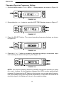
Changing Receiver Frequency Setting
1. Press the MENU button. The “+ MENU –” display appears, as shown in Figure 16.
FIGURE 16
2. Press either the + or – button to reach the SET FREQ display, shown in Figure 17.
FIGURE 17
3. Press the SELECT button. The current operating frequency displays, as shown
in Figure 18.
FIGURE 18
4. Press the “+” or “–” button to increase or decrease the setting in incremental steps
until reaching the desired frequency. See Figure 19.
FIGURE 19
NOTE: The receiver operating frequency actually changes the moment you press
the + and – buttons. As the frequency changes, the G/CH number automatically
changes. By observing the RF lights on the receiver, you can see which frequen-
cies are already being used and avoid interference. If more than 20 seconds of
inactivity elapse, the display will return to the original settings.

ENGLISH
15
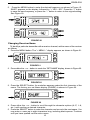
5. Press the MENU button to enter the desired frequency, as shown in Figure 15.
SAVE? appears on the display, followed by “+ YES – NO”. Press the “+” button
to save the new frequency, or press the “–” button to return to the original setting.
See Figure 20.
FIGURE 20
Changing Receiver Name
To identify a particular transmitter with a receiver channel, set the name of the receiver
as follows:
1. Press the MENU button. The “+ MENU –” display appears, as shown in Figure 21.
FIGURE 21
2. Press either the + or – button to reach the “SET NAME” display, shown in Figure 22.
FIGURE 22
3. Press the SELECT button. An underline appears under the first character of the
name. The factory pre–set Name display (SHURE) is shown in Figure 23.
FIGURE 23
4. Press either the + or – button to scroll through the character options (A–Z, 1–9,
etc.) until reaching a desired character.
5. Press the SELECT button to enter the character and move to the next space. You
may enter a name up to eight characters long, including blank spaces. Continue
until you have spelled out the entire name.

ENGLISH
16
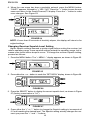
6. When the new name has been completely entered, press the MENU button.
“SAVE?” appears, followed by “+ YES – NO”. Press the “+” button to save the new
name and return to the Group/Channel/TV display. Press the “–” button to make
more changes. See Figure 24.
FIGURE 24
NOTE: If more than 20 seconds of inactivity elapse, the display will return to the
original settings.
Changing Receiver Squelch Level Setting
Higher squelch settings demand a quieter signal before muting the receiver, but
reduce operating range. Lower squelch settings extend the operating range, but in-
crease noise levels before dropout occurs. To change the receiver Squelch setting,
proceed as follows:
1. Press the MENU button. The “+ MENU –” display appears, as shown in Figure 25.
FIGURE 25
2. Press either the + or – button to reach the “SET SQCH” display, shown in Figure 26.
FIGURE 26
3. Press the SELECT button to display the current squelch level, as shown in Figure
27 (factory preset value is “0.0”).
FIGURE 27
MID
4. Press either the “+” or “–” button to change the Squelch setting in increments of
0.5 until reaching the desired level. The Squelch setting actually changes the mo-
ment you press the “+” and “–” buttons.

ENGLISH
17
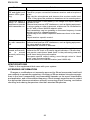
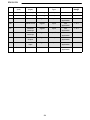
NOTE: The highest possible squelch setting is +10.0 and the lowest possible
squelch setting is –10.0, as shown in the following table . However, the factory
preset level of 0.0 usually will not need to be changed.*
Receiver Squelch Control Settings
DISPLAY dBm*
Maximum 10 –83.0
9.5 –86.0
9.0 –87.0
8.5 –87.5
8.0 –88.0
7.5 –88.5
7.0 –89.0
6.5 –89.5
6.0 –90.0
5.5 –90.5
5.0 –91.0
4.5 –91.5
4.0 –92.0
3.5 –92.3
3.0 –92.7
2.5 –93.0
2.0 –93.3
1.5 –93.6
1.0 –93.9
0.5 –94.2
Midrange 0 –94.5
–0.5 –94.8
–1.0 –95.1
–1.5 –95.4
–2.0 –95.7
–2.5 –96.0
–3.0 –96.3
–3.5 –96.6
–4.0 –96.9
–4.5 –97.2
–5.0 –97.5
–5.5 –97.8
–6.0 –98.1
–6.5 –98.4
–7.0 –98.7
–7.5 –99.0
–8.0 –99.3
–8.5 –99.6
–9.0 –99.9
–9.5 –100.2
Minimum –10 Open
*U4S and U4D squelch values differ slightly.
Specifications subject to change without notice.

ENGLISH
18
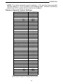
5. Once you have reached the desired squelch level, press the MENU button.
“SAVE?” appear, followed by “+ YES – NO”, as shown in Figure 28. Press the –
button to make more changes, or press + to save the new squelch setting and re-
turn to the Group/Channel/TV display.
FIGURE 28
NOTE: If more than 20 seconds of inactivity elapse, the display returns to the origi-
nal settings.
Locking the Receiver Display
1. Press the MENU button. The “+ MENU –” display appears, as shown in Figure 29.
FIGURE 29
2. Press either the + or – button to reach the “SET LOCK” display, as shown in Figure
30.
FIGURE 30

ENGLISH
19
3. Press the SELECT button. The “CODE?” display appears, as shown in Figure 31.
FIGURE 31
4. Press +, –, +, in that order, to engage the display lock. The display shown in Fig-
ure 32 appears.
FIGURE 32
NOTE: Write down the lock code (+, –, +) and keep it in a secure place. If no code is
entered, the system times out and return to the main display.
5. A small “lock” symbol appears in the upper right corner of the status screen dis-
plays, as shown in Figure 33. The lock symbol indicates the receiver is in the lock
mode.
GROUP
CHANNEL
TV
FIGURE 33
Unlocking the Receiver Display
To disengage the lock, press the MENU button. When “CODE?” appears, press
+, –, + , in that order, then press the MENU button.
NOTE: Once the lock function is engaged, any attempt to change settings causes
“CODE?” to appear. If the incorrect code is entered, “INVALID” appears, prevent-
ing the user from changing any settings.
Page is loading ...
Page is loading ...
Page is loading ...
Page is loading ...
Page is loading ...
Page is loading ...
Page is loading ...
Page is loading ...
Page is loading ...
Page is loading ...
Page is loading ...
Page is loading ...
Page is loading ...
Page is loading ...
Page is loading ...
Page is loading ...
-
 1
1
-
 2
2
-
 3
3
-
 4
4
-
 5
5
-
 6
6
-
 7
7
-
 8
8
-
 9
9
-
 10
10
-
 11
11
-
 12
12
-
 13
13
-
 14
14
-
 15
15
-
 16
16
-
 17
17
-
 18
18
-
 19
19
-
 20
20
-
 21
21
-
 22
22
-
 23
23
-
 24
24
-
 25
25
-
 26
26
-
 27
27
-
 28
28
-
 29
29
-
 30
30
-
 31
31
-
 32
32
-
 33
33
-
 34
34
-
 35
35
-
 36
36