
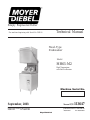
Technical Manual
For machines beginning with Serial No. W8100
Model
Hood-Type
Dishwasher
Moyer Diebel Ltd.
September, 2003
Manual P/N 113647
MH65-M2
High Temperature
with Built-in Booster
Machine Serial No.
Simply Engineered Better
P. O. Box 4149
Winston-Salem, North Carolina 27115-4149
336/661-1556 Fax: 336/661-1660
2674 N. Service Road
Jordan Station, Ontario, Canada L0R 1S0
905/562-4195 Fax: 905/562-4618

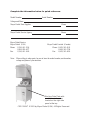
Complete the information below for quick reference.
Model Number Serial Number
Voltage and Phase
Moyer Diebel Parts Supplier Phone
Moyer Diebel Service Agency Phone
Note: When calling to order parts, be sure to have the model number, serial number,
voltage and phase of your machine.
COPYRIGHT © 2003 by Moyer Diebel (USA). All Rights Reserved.
Machine Data Plate with
model & serial number
located on the right side
panel at the top.
Moyer Diebel Service:
Moyer Diebel (USA) Moyer Diebel Limited (Canada)
Phone: 1 (336) 661-1556 Phone: 1 (905) 562-4195
1 (800) 858-4477 1 (800) 263-5798
Fax: 1 (336) 661-1660 Fax: 1 (905) 562-4618

i
REVISION RECORD
Revision Revised Serial Number Comments
Date Pages Effectivity
7/3/03 All W8100 First issue of manual and
replacement parts lists
REVISION RECORD

ii
REVISION RECORD
Revision Record (CONT.)

iii
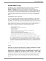
LIMITED WARRANTY
Limited Warranty
Moyer Diebel, P.O. Box 4183, Winston-Salem, North Carolina 27115, and P. O. Box 301, 2674 North Service
Road, Jordan Station, Ontario, Canada L0R 1S0 warrants machines, and parts, as set out below.
Warranty of Machines: Moyer Diebel warrants all new machines of its manufacture bearing the name
“Moyer Diebel” and installed within the United States and Canada to be free from defects in material and workman-
ship for a period of one (1) year after the date of installation or fifteen (15) months after the date of shipment by
Moyer Diebel, whichever occurs first. [See below for special provisions relating to Model Series DF and SW.] The
warranty registration card must be returned to Moyer Diebel within ten (10) days after installation. If warranty card
is not returned to Moyer Diebel within such period, the warranty will expire after one year from the date of ship-
ment.
Moyer Diebel will not assume any responsibility for extra costs for installation in any area where there are
jurisdictional problems with local trades or unions.
If a defect in workmanship or material is found to exist within the warranty period, Moyer Diebel, at its elec-
tion, will either repair or replace the defective machine or accept return of the machine for full credit; provided,
however, as to Model Series DF and SW, Moyer Diebel’s obligation with respect to labor associated with any re-
pairs shall end (a) 120 days after shipment, or (b) 90 days after installation, whichever occurs first. In the event that
Moyer Diebel elects to repair, the labor and work to be performed in connection with the warranty shall be done
during regular working hours by a Moyer Diebel authorized service technician. Defective parts become the property
of Moyer Diebel. Use of replacement parts not authorized by Moyer Diebel will relieve Moyer Diebel of all further
liability in connection with its warranty. In no event will Moyer Diebel’s warranty obligation exceed Moyer
Diebel’s charge for the machine. The following are not covered by Moyer Diebel’s warranty:
a. Lighting of gas pilots or burners.
b. Cleaning of gas lines.
c. Replacement of fuses or resetting of overload breakers.
d. Adjustment of thermostats.
e. Adjustment of clutches.
f. Opening or closing of utility supply valves or switching of electrical supply current.
g. Adjustments to chemical dispensing equipment.
h. Cleaning of valves, strainers, screens, nozzles, or spray pipes.
i. Performance of regular maintenance and cleaning as outlined in operator’s guide.
j. Damages resulting from water conditions, accidents, alterations, improper use, abuse,
tampering, improper installation, or failure to follow maintenance and operation procedures.
Examples of the defects not covered by warranty include, but are not limited to: (1) Damage to the exterior or
interior finish as a result of the above, (2) Use with utility service other than that designated on the rating
plate, (3) Improper connection to utility service, (4) Inadequate or excessive water pressure, (5) Corrosion
from chemicals dispensed in excess of recommended concentrations, (6) Failure of electrical components due
to connection of chemical dispensing equipment installed by others, (7) Leaks or damage resulting from such
leaks caused by the installer, including those at machine table connections or by connection of chemical dis-
pensing equipment installed by others, (8) Failure to comply with local building codes, (9) Damage caused by
labor dispute.
Warranty of Parts: Moyer Diebel warrants all new machine parts produced or authorized by Moyer Diebel to be
free from defects in material and workmanship for a period of 90 days from date of invoice. If any defect in mate-
rial and workmanship is found to exist within the warranty period Moyer Diebel will replace the defective part with-
out charge.
DISCLAIMER OF WARRANTIES AND LIMITATIONS OF LIABILITY. MOYER DIEBEL’S WARANTY
IS ONLY TO THE EXTENT REFLECTED ABOVE. CHAMPION MAKES NO OTHER WARRANTIES,
EXPRESS OR IMPLIED, INCLUDING, BUT NOT LIMITED, TO ANY WARRANTY OF
MERCHANTABILITY, OR FITNESS OF PURPOSE. MOYER DIEBEL SHALL NOT BE LIABLE FOR
INCIDENTAL OR CONSEQUENTIAL DAMAGES. THE REMEDIES SET OUT ABOVE ARE
THE EXCLUSIVE REMEDIES FOR ANY DEFECTS FOUND TO EXIST IN MOYER DIEBEL
DISHWASHING MACHINES AND MOYER DIEBEL PARTS, AND ALL OTHER REMEDIES ARE EX-
CLUDED, INCLUDING ANY LIABILITY FOR INCIDENTALS OR CONSEQUENTIAL DAMAGES.
Moyer Diebel does not authorize any other person, including persons who deal in Moyer Diebel Dishwashing
Machines to change this warranty or create any other obligation in connection with Moyer Diebel Dishwashing
Machines.

iv
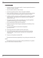
FOREWORD
1. Read the instructions in this manual carefully. It contains important information on
installation, operation, and safety.
2. Store this manual carefully for future reference.
3. After removing packing material, check for loose parts in dishracks.
4. Before switching the equipment on, make sure that the model data plate conforms
to the electrical and water requirements supplied to this particular machine.
5. Installation should be carried out by qualified personnel according to the manufac-
turers instructions. The installation of your machine must meet all applicable
health and safety codes.
6. This equipment should be used for its intended purpose. Any other application
should be considered improper and therefore dangerous.
7. Only trained personnel should operate this equipment.
8. Operators must strictly follow all hygienic requirements in the handling of clean
dishware or cutlery.
9. Do not leave the machine in an environment at temperatures
lower than 0°C/32°F.
10. This machine should not be washed with a direct water stream.
11. Only qualified personnel should access the control panel after disconnecting
main power supply. Tag the disconnect indicating work is being performed
on that circuit.
12. Noise level of the machine is less than 67dB.
The manufacturer declines any responsibility for any printing errors contained in this
booklet.
The manufacturer also reserves the right to make any modifications to its products
that do not affect the basic characteristics thereof.
FIV

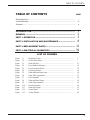
Revision Record........................................................................................................... i
Limited Warranty......................................................................................................... iii
Foreward ...................................................................................................................... iv
INTRODUCTION .......................................................................... 1
GENERAL .................................................................................... 2
PART 1: OPERATION ................................................................... 3
PART 2: INSTALLATION AND MAINTENANCE ............................ 8
PART 3: REPLACEMENT PARTS .................................................. 11
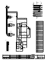
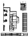
PART 4: ELECTRICAL SCHEMATICS ........................................... 39
TABLE OF CONTENTS
v
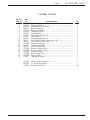
TABLE OF CONTENTS PAGE
LIST OF FIGURES
Figure 1.1 – Operations Detail ................................................................................... 3
Figure 1.2 – Control Panel Detail ............................................................................... 7
Figure 3.1 – Hood and Tank........................................................................................ 12
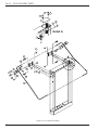
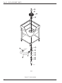
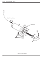
Figure 3.2 – Door Handle and Springs........................................................................ 14
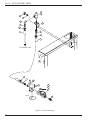
Figure 3.3 – Door Switch and Block........................................................................... 16
Figure 3.4 – Tracks and Screens.................................................................................. 18
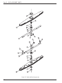
Figure 3.5 – Wash and Rinse Spray Arms .................................................................. 20
Figure 3.6 – Water Tank Components......................................................................... 22
Figure 3.7 – Drain Assembly ...................................................................................... 24
Figure 3.8 – Wash and Rinse Piping ........................................................................... 26
Figure 3.9 – Wash Pump Assembly ............................................................................ 28
Figure 3.10 – Booster Assembly ................................................................................... 30
Figure 3.11 – Water Inlet Piping ................................................................................... 32
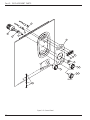
Figure 3.12 – Control Panel .......................................................................................... 34
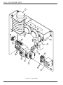
Figure 3.13 – Control Cabinet....................................................................................... 36

vi
This Page
Intentionally
Left
Blank
Part 1: INSTALLATION AND MAINTENANCE

1
INTRODUCTION
INTRODUCTION
Welcome to Moyer Diebel... and thank you for allowing us to take care of your dishwashing
needs.
This manual covers the hood-type dishwasher model MH-65.
Your machine was completely assembled , inspected and thoroughly tested at our factory before it
was shipped to your installation site.
This manual contains:
• Installation and Instructions
• Operation and Cleaning Instructions
• Troubleshooting Guide
• Basic Service Information
• Replacement Parts Lists
• Electrical Schematics
All information, illustrations and specifications contained in this manual are based upon the latest
product information available at the time of publication. Moyer Diebel constantly improves its
products and reserves the right to make changes at any time or to change specification without
notice and without incurring any obligations.
For your protection, factory authorized parts should always be used for repairs.
Replacement parts may be ordered from your Moyer Diebel authorized parts distributor or
authorized service agency. When ordering parts, please supply the model number, serial number,
voltage and phase of your machine, the part number, part description and quantity.

2
GENERAL
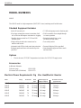
MODEL NUMBERS
MH-65
The MH-65 model is a high temperature (180°F/82°C rinse) sanitizing model with booster.
Standard Equipment Includes:
• Quick 65 second cycle • 1.5 HP wash pump on anti-vibration pads
• Four large rectangular screens to maximize food • Field convertible from straight through
soil collection and improve resistance to clogging to corner operation
• Variable selector switch for 65, 120 and 180 • Extended wash/de-lime cycles
seconds cycles (for heavily soiled items)
• Single electrical and water connections for • Door safety switch
machine and booster
• Automatic tank fill/low-tank water heat protection • Pressure Reducing Valve provided
•Detergent probe and rinse-aid connection points • Interchangeable upper and lower wash
provided and rinse arms
Options
• Electric booster (70°F/39°C temperature rise) heater for 110°F/43°C supply water
Accessories
Additional dishracks:
Dish rack (peg) P/N 101285
Silverware rack (flat bottom) P/N 101273
Electrical Power Requirements: Fig Elec Heat/Electric Booster
Model Voltage Booster Rise Rated Minimum Supply Ckt. Maximum Overcurrent
Amps Conductor Ampacity Protective Device
MH-65 208/60/1 40 45 Amps 60 Amps 60 Amps
MH-65 240/60/1 40 51 Amps 70 Amps 70 Amps
MH-65 208/60/3 40 26 Amps 35 Amps 35 Amps
MH-65 240/60/3 40 29 Amps 40 Amps 40 Amps
MH-65 208/60/3 70 37 Amps 50 Amps 50 Amps
MH-65 240/60/3 70 42 Amps 60 Amps 60 Amps

3
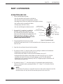
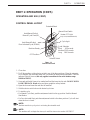
Auto/Manual Switch
Manual Cycle Start(UP)
Auto Manual Switch
Door Activated Cycle (DOWN)
Selector Switch
Extended Wash
Manual Start Switch
Machine Ready
Heater OFF Light
(Only on S/N W8100-W8135)
(B)
In Cycle Light
(D)
Cycle Selection
Short - 65 Seconds
Medium-120 Seconds
Long -180 Seconds
OFF Position
(E)
(L)
(C)
(A)
(M)
PART 1: OPERATION
PART 1: OPERATION
OPERATION AND USE
1. Before washing make sure that:
• the wall-mounted on/off switch is switched on;
• the water tap is open and water pressure is present,
• the pump suction filters are installed in their proper locations;
• the overflow tube is inserted in the drain;
• rotating spray arms move freely;
• the rinse and detergent containers are full;
2. Set switch “A” to position 1 to enable the
automatic filling of the wash tank. Once
the wash tank has filled and the tank heater
turns on to make the tank reach temperature, the
heater then turns off and lamp “B” turns on
(this applies only to machines in the serial
number range W8100 to W8135).
3. Scrap and preflush all items to be washed
and load the items into the rack. Do not overload the rack. Wash only one layer of silver-
ware in a rack.
4. Open the door and insert the rack into the machine.
5. By means of switch “A” select the wash cycle according to conditions of the dishware:
• with glasses or cups select the short cycle (pos.1)
• with normally dirty dishes or cutlery select the medium cycle (pos.2)
• with particularly dirty dishes or deep dishes select the long cycle (pos.3), or flip the
extended wash switch (E) down (only after starting a cycle). This will make the
dishmachine cycle in wash continuously until (E) is flipped up again; the machine will
then resume its normal cycle.
6. By means of selector “L”, select the wash cycle for automatic start when the hood is
closed, or for manual start by pressing the button “M”. Lamp “D” will switch off at the
end of the cycle.
NOTE:
This machine will continue to wash until the booster tank reaches temperature and the
thermostat shuts off; only then will the machine proceed to the rinse cycle.
Figure 1.1 Operation Detail

4
!
Part 1: OPERATION
PART 1: OPERATION (CONT.)
OPERATION AND USE (CONT.)
7. Remove the rack at a slight incline to permit all the water to drain; allow dishware to dry.
After washing one’s hands, handle the rack in such a manner as not to touch the
dishware inside, then place the rack on hygienically clean shelves.
8. At the end of washing, turn switch “A” to position “0”, empty out the tank by removing
the overflow tube. Then close the door and turn switch “A” to position “1” for a few
minutes to rinse out the inside of the machine. Finally, turn the switch “A” to position “0”
and wait until the tank is completely empty.
The scrap screens can now be taken out, washed, and then replaced.
Be certain that the overflow tube has been reinstalled.
9. When finished washing, switch off the machine by turning off the main disconnect switch
and turn off the water supply.
INSTRUCTIONS DURING THE WASH CYCLE
1. Do not put your hands into the water containing detergent. If this happens, wash them
immediately and thoroughly with fresh water.
2. Use only commercial non-foaming detergents.
3. When the machine is operating, do not open the door too quickly.
4. In the event the machine does not work properly, turn off the main power disconnect
switch and contact a technical service center authorized by the manufacturer for repairs.
5. Never modify the thermostat settings.
6. Wash tank water should be changed every two hours or after each meal period.
7. Do not subject clean dishware to any further cleansing treatment such as brushes or drying
towels.
CAUTION:
If these instructions are not followed, your safety and the equipment can be compromised.

5
MAINTENANCE:
IMPORTANT:
Before carrying out the cleaning and maintenance operations, turn off the main discon-
nect switch for the equipment.
Frequently check and clean the nozzles. Blocked nozzles will prevent the machine from
cleaning properly.
Do not use corrosive products such as sodium hypochlorite (bleach), acids, steel wool or
steel brushes to clean the inside and outside of the machine.
The presence of calcium and magnesium salt in the water can compromise machine
performance. Ask a qualified chemical person to remove the deposits periodically.
Stainless steel surfaces should be well cleaned in order to avoid some oxidation risks, or
chemical reactions.
OPTIMAL RESULTS:
Poor wash results can be noted when residue remains on the dishware.
Poor results can be caused by an insufficient rinse: in this case check that the rinse nozzles
are clean and that there is sufficient water supply pressure (20-22 PSI/138-151 kPa) during
machine rinse cycle..
In case of dishware residue check that:
• the washing nozzles are clean
• the wash water temperature is a minimum of 60°C/140°F
• there is detergent in the container
• the pump suction filter is clean
• the racks are suitable for the dishes and cutlery that are to be washed
• the position of the cutlery and the dishes in the racks are correct
• the racks are not overloaded with wares
TEMPORARY MACHINE NONUSE:
In case the machine is not used for a prolonged period, it is recommended to fill the
wash tank and run the machine with clean water, then drain, in order to avoid the
forming of bad odors.
If necessary repeat this step until all water leaving the machine is clean.
If the machine is not used for long periods, it is recommended to oil the stainless steel
surfaces with paraffin oil and to empty the water from the booster tank and the wash
pump.
PART 1: OPERATION

6
PART 1: OPERATION (CONT.)
OPERATION AND USE (CONT.)
SANITIZING THE MACHINE
Sanitizing the machine at least once a week is of the utmost importance in order to
guarantee hygiene, even when the machine is not in use.
It is advisable to use a disinfecting product suggested by an authorized detergent dealer.
Before turning off the machine, run the machine briefly with clean water.
HARD WATER CONDITIONS
In hard water locations, mineral deposits will form inside the machine and also on
dishware.
In order to avoid the above conditions delime the machine on a regular basis.
Part 1: OPERATION

7
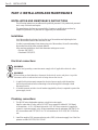
Auto/Manual Switch
Manual Cycle Start(UP)
Auto Manual Switch
Door Activated Cycle (DOWN)
Selector Switch
Extended Wash
Manual Start Switch
Machine Ready
Heater OFF Light
In Cycle Light
Cycle Selection
Short - 65 Seconds
Medium-120 Seconds
Long -180 Seconds
OFF Position
(Only on S/N W8100-W8135)
PART 1: OPERATION
Figure 1.1-
Control Panel Detail
PART 1: OPERATION (CONT.)
OPERATION AND USE (CONT.)
CONTROL PANEL LAYOUT
1. Close door.
2. To fill the machine, set the selector switch to any of the three positions. When the automatic
fill is complete, the wash tank heater will cut on until the tank reaches temperature. Then the
indicator light will turn on (this only applies to machines in the serial number range
W8100 to W8135).
3. Scrap and preflush all items to be washed and load the items into the rack. DO NOT OVER-
LOAD THE RACK. Wash cutlery and place upright in cutlery baskets.
4. Open the door and insert the rack into the machine.
5. With the selector switch choose the desired cycle time.
6. To start the cycle:
• For Manual Cycle Start, push the auto/manual switch to the up position. Push the Manual
Start Button.
• For Door Activated Start, push the auto/manual switch to the down position. Cycle will start
when the door is closed.
NOTE:
Machine must be in cycle prior to activating the extended wash.
NOTE:
This machine will not begin the rinse cycle until the rinse water reaches 180°F/82°C.

8
PART 2: INSTALLATION AND MAINTENANCE
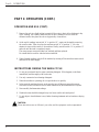
INSTALLATION AND MAINTENANCE INSTRUCTIONS
The following instructions are addressed to qualified personnel. Only authorized personnel
are to carry out checks and repairs.
The manufacturer declines any responsibility if repairs or modifications are done by
unqualified personnel or if parts are not supplied by the manufacturer.
Installation
Level the machine by placing a level on the top of the machine and adjusting the feet.
Level the machine front to back and side to side.
In order to prevent damage from steam going out of the machine, the walls surrounding
the machine should be water resistant material.
After machine installation, check that thermostat settings are correct.
• Booster 180°F/82°C.
• Wash tank 150°F/68°C.
Electrical connections
WARNING:
Electrical and grounding connections must comply with all applicable electrical codes.
WARNING:
When working on the dishwasher, disconnect the electrical service and place a tag at the
disconnect switch to indicate that work is being done on that circuit.
1. A qualified electrician must compare the electrical power supply with the machine
electrical specifications before connecting to the incoming service through a fused
disconnect switch.
2. A fused disconnect switch or circuit breaker (supplied by others) is required to protect the
power supply circuit.
Plumbing connections
1. The MH-65 series dishwasher requires a single hot water supply.
Install a water shut off valve with a 3/4" NPT hose connection within 40" (1016mm)
of the machine. A 6 ft. (1829mm) hose with a 3/4" NPT hose connector is supplied to
connect to customers supply valve. Water temperature must be minimum 140°F/60°C for
40° rise machines and 110°F/43°C for 70° rise machines at 20-22 PSI/138-151 kPa flow
rate.
2. Install the supplied 3/4" pressure reducing valve (PRV) in the water supply line if the flow
pressure exceeds 20-22 PSI/138-151 kPa.
Part 2: INSTALLATION

9
!
PART 2: INSTALLATION AND MAINTENANCE (CONT.)
Drain connections
1. The MH65 model is a gravity drain machine equipped with a 1-3/8" O.D. tailpiece and a 6
foot long 1" I.D. hose.
2. The maximum drain flow rate is 15 gallons/min-56.8 litres/min.
3. Drain height must not exceed 11" (280mm) above finished floor.
4. The drain connection is made to the dishwasher from underneath the machine through an
access hole in the machine base.
Ventilation
NOTE:
Ventilation must comply with local sanitary and plumbing codes.
CAUTION:
Exhaust air should not be vented into a wall, ceiling, or concealed space of a building.
Condensation can cause damage.
Part 2: INSTALLATION AND MAINTENANCE

10
This Page
Intentionally
Left
Blank

11
Part 3: REPLACEMENT PARTS
PART 3:
REPLACEMENT
PARTS

12
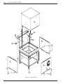
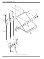
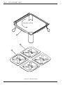
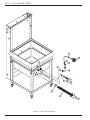
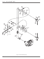
Part 3: REPLACEMENT PARTS
Figure 3.1- Hood and Tank
1
2
1
B
4
A
A
A
7
3
5
6
6
Page is loading ...
Page is loading ...
Page is loading ...
Page is loading ...
Page is loading ...
Page is loading ...
Page is loading ...
Page is loading ...
Page is loading ...
Page is loading ...
Page is loading ...
Page is loading ...
Page is loading ...
Page is loading ...
Page is loading ...
Page is loading ...
Page is loading ...
Page is loading ...
Page is loading ...
Page is loading ...
Page is loading ...
Page is loading ...
Page is loading ...
Page is loading ...
Page is loading ...
Page is loading ...
Page is loading ...
Page is loading ...
Page is loading ...
Page is loading ...
Page is loading ...
-
 1
1
-
 2
2
-
 3
3
-
 4
4
-
 5
5
-
 6
6
-
 7
7
-
 8
8
-
 9
9
-
 10
10
-
 11
11
-
 12
12
-
 13
13
-
 14
14
-
 15
15
-
 16
16
-
 17
17
-
 18
18
-
 19
19
-
 20
20
-
 21
21
-
 22
22
-
 23
23
-
 24
24
-
 25
25
-
 26
26
-
 27
27
-
 28
28
-
 29
29
-
 30
30
-
 31
31
-
 32
32
-
 33
33
-
 34
34
-
 35
35
-
 36
36
-
 37
37
-
 38
38
-
 39
39
-
 40
40
-
 41
41
-
 42
42
-
 43
43
-
 44
44
-
 45
45
-
 46
46
-
 47
47
-
 48
48
-
 49
49
-
 50
50
-
 51
51


Moyer Diebel MH65-M2 User manual
- Category
- Dishwashers
- Type
- User manual
Ask a question and I''ll find the answer in the document
Finding information in a document is now easier with AI
Related papers
-
Moyer Diebel MH65-M2 User manual
-
-
-
-
-
-
-
-
-
Other documents
-
 T'nB IPHSTYL Datasheet
-
 COMENDA LF321 User manual
-
Champion I-DH User manual
-
-
Eagle Group MD240HT Datasheet
-
-
Metos WD-4 Operating instructions
-
Jet Tech 737-DP User manual
-
Jet Tech 727 User manual
-
Champion D-H1M5 User manual

