Page is loading ...

TECHNICAL SPECIFICATION
3 P 3 w
TERMINAL CONNECTION
PTC-4202A-M1
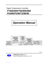
MECHANICAL INSTALLATION
PROCESS TEMPERATURE CONTROLLER
PV = Process value
SV = Set Value
48
95
45
45
3
48
Outline Dimension (mm) Panel Cutout
Dimension (mm)
AO
O/P1
O/P2
TUNE
SET ENT
RX
TX
AT
4485
PTC 4202A-M1
SV
PV
4500
Input Types
Resolution
Indication
Accuracy
Input Range
0 to 600°C,
0 to 1200°C,
-99 to 400°C,
-99.9 to 400.0°C,
-999 to 9999
-999 to 9999
-999 to 9999
J
K
PT-100
PT.1
0-10V DC
0-20mA DC
4-20mA DC
J,K,PT-100 = 1°C
±1% of FSD ± 1°C
PT.1 = 0.1°C
Display
Heating
Size
Keys
Cooling
Panel Cutout
Upper: 4 digit, 7 segment, 0.39” White
1) PID control with Auto-Tuning
1) BL.TP (Blower Time Proportion)
Lower: 4 digit, 7 segment, 0.28” Green
2) ON-OFF control
2) ON-OFF control
48 (H) x 48 (W) x 95 (D) mm
SET, INC, DEC, ENT
45 (H) x 45 (W) mm
(FSD:- full scale deflection)
CONTROL METHOD:
INPUT SPECIFICATION:
DISPLAY AND KEYS:
DIMENSION:
CONTROL METHOD:
0-10V DC,0-20mA DC,4-20mA DC
= 0.1,0.01,0.001,0001
OUTPUT SPECIFICATION
AUXILIARY SUPPLY
Relay
Supply voltage
Relay Type
Power consumption
(VA RATING)
Rating
2 nos.
(NO-C)
Approx 7 VA @ 230V AC MAX
5A, 230V AC/30 V DC
ENVIRONMENT CONDITION
Relative Humidity
Protection
Level
Operating Temp. 0°C to 55°C
UP to 95% RH
(non-condensing)
IP-65 (Front side) As per IS/IEC
60529 : 2001
100 to 250V AC, 50-60Hz
Relay Output
Analog Output
Controlling Output 4 to 20mA DC
R1
C
NO
1
2
3
4
5
L
N
100
250V AC
~
50/60 Hz
7VA
www.multispanindia.com
Made in India
PTC 4202A-M1-WG
+
-
O/P
4-20mA DC
RS
485
MODBUS
D + D -
T/C
++
0/4-20
mA DC
0-10V DC
6
7
8
9
10
-
RTD
C
NO
R2
!

Read complete instructions prior to installation
and operation of the unit.
WARNING : Risk of electric shock.
All safety related codifications, symbols and instructions that
appear in this operating manual or on the equipment must be
strictly followed to ensure the safety of the operating personnel
as well as the instrument.
If all the equipment is not handled in a manner specified by
the manufacturer, it might impair the protection provided by the
equipment.
WARNING : Risk of electric shock.
1. To prevent the risk of electric shock, power supply to the
equipment must be kept OFF while doing the wiring
arrangement. Do not touch the terminals while power is
being supplied.
2. To reduce electro magnetic interference, use wire with
adequate rating and twists of the same of equal size shall
be made with shortest connection.
3. Cable used for connection to power source, must have a
cross section of 1mm or greater. These wires should have
insulations capacity made of at least 1.5kV.
5. A better anti-noise effect can be expected by using
standard power supply cable for the instrument.
1. This equipment, being built-in-type, normally becomes a
part of main control panel and in such case the terminals
do not remain accessible to the end user after installation
and internal wiring.
2. Do not allow pieces of metal, wire clippings, or fine metallic
fillings from installation to enter the product or else it may
lead to a safety hazard that may in turn endanger life or
cause electrical shock to the operator.
3. Circuit breaker or mains switch must be installed between
power source and supply terminal to facilitate power ‘ON’
or ‘OFF’ function. However this mains switch or circuit
breaker must be installed at convenient place normally
accessible to the operator.
4. Use and store the instrument within the specified ambient
temperature and humidity ranges as mentioned in this
manual.
1. Prepare the panel cutout with proper dimensions as shown
above.
2. Fit the unit into the panel with the help of clamp given.
3. The equipment in its installed state must not come in close
proximity to any heating source, caustic vapors, oil steam,
or other unwanted process byproducts.
4. Use the specified size of crimp terminal (M3.5 screws) to
wire the terminal block. Tightening the screws on the
terminal block using the tightening torque of the range of
1.2 N.m.
5. Do not connect anything to unused terminals.
1. The equipment should be cleaned regularly to avoid blockage
of ventilating parts.
2. Clean the equipment with a clean soft cloth. Do not use
isopropyl alcohol or any other cleaning agent.
3. Fusible resistor must not be replaced by operator.
SAFETY PRECAUTION
!
WARNING GUIDELINES
INSTALLATION GUIDELINES
MECHANICAL INSTALLATION GUIDELINES
4. When extending the thermocouple lead wires, always use
thermocouple compensation wires for wiring for the RTD
type, use a wiring material with a small lead resistance
(5 max per line) and no resistance differentials among
three wires should be present.
STATUS LED DESCRIPTION
To enter in parameter setting
For start/stop PID auto tuning Press
6 sec
Press 3 sec
+
To go in factory setting mode
PRESS KEYFUNCTION
OPERATOR MODE
PARAMETER SETTING MODE
To set parameter value
To increment parameter value.
To decrement parameter value.
Set parameter to be save & exit.
1
2
3
1 - Analog output
2 - Output 1
3 - Output 2
2345
2500
4
5
6
4 - Receive
5 - Transmit
6 - Auto tuning
KEY OPERATION
MAINTENANCE

Page 2
FACTORY SETTING PARAMETER MESSAGE DESCRIPTION
ENT
ENT
: press key to apply factory set
values as shown in table.
: press key to escape
from factory setting.
Press+key
for3sec
PARAMETER
IT
CT
PB
DT
MR
OFFSET
HYSTERISIS-1
HYSTERISIS-2
C-PB
C-ON
C-OFF
VALUES
300
15 sec
75
1 Sec
48Sec
2
4
6
1
3
5
7
8
9
10
11
12
20.0°
C
3°
C
3°
C
4.0°
C
CRFC 0
0°
C
0°
C
SET1
LOW1
LOW2
SET2
HI 2
H1 1
Set Point 1 For O/P 1
Set Point 2 For O/P 2
Low Set Point 1
High Set Point 1
Low Set Point 2
High Set Point 2
PASS
INPT
Password
Input ( Sensor )
C SET
Controlling O/P Set Point
SLL Set Low Limit
Set High Limit
Offset
Proportional Band For PID Action
Integral Time Constant
Derivative Time Constant
Cycle Time For PID Action
Manual Reset
Cooling PB
Cooling On Time
Cooling Off Time
Hysterisis 1
SHL
OFST
PB
IT
DT
CT
R
C-PB
C-ON
C-OF
HYS1
M
Hysterisis 2
HYS2
S T
SOA
OUT1
S UT
OutPut 1 Mode
Soak Time Select
Soak Mode
Soak Unit
Soak Time Value
h
h
h
E O Soak Time Memory
Alarm 2
Set 2 Mode
Relay 1 Delay Time
Relay 2 Delay Time
Alarm Time
PID Action
ON-OFF Action
Blower TP Action
High Alarm
Absolute Low Alarm
In Band Alarm
Absolute Out Band Alarm
Heating Mode
Cooling Mode
Alarming Mode
OFF Mode
Yes
No
Save
Set 2 Individual to Set 1
Set 2 Reletive to Set 1
Second
Hour
Minute
Factory Setting
AL 2
S2 D
R1DL
R2DL
ALT
PID
OnOf
BL.tp
ab-L
In-b
ab-O
HEAT
COOL
aLr
Off
Yes
NO
Save
IndI
SEC
HOUR
RLTV
IN
FCST
HIH
S MD
h
M
M M
M
M
M
M
M
END Soak Time End
CTR1
OUT2
Control Action 1
Output 2 Mode
Control Action 2
Alarm 1
CTR2
ALM1
Analog Output
AOuT
BASE
MBUS Modbus
PV
SV
4-20
PERC
Basic Configuration
Retransmission O/P On PV
Retransmission O/P On SV
Manual Selection Of
4-20 mA Analog O/P
Percentage wise Selection Of
4-20 mA Analog O/P (Manually)
CON Controlling Output
PARAMETER MESSAGE DESCRIPTION

ERROR
OPEN
SRE
MEANING
When an error has occurred the display indicates error codes
as given below.
Sensor is not connected
Over range condition
or sensor break
Sensor connection is reversed
OUER
LO
Over range condition
When I/P is 4 to 20mA DC
is selected, than I/P signal is
lower than SLL (0-5mA)
For 0 to 10V DC -
For 4 to 20mA DC -
exceed 10V DC
exceed 20mA DC
v
LOPC Low percentage
HIPC High percentage
FRWD Forword
REVR Reverse
ADDR Address
BAUD Baud Rate
PRTY Parity
DATA Data Type
SINT Intenger
FLOT Float
RANGE FOR CONTROL PARAMETER
Range for PT.1 Sensor
0.0 to 999.9°C
0 to 9999
0 to 9999
4 to 99 sec
0.1 to 100.0°C
0.1 to 100.0°C
1 to 20 sec
2.0 to 25.0°C
5 to 200 sec
0.0 to 99.59 mm.ss
0.0 to 99.59 mm.ss
0 to 99 sec
-9.0 to 9.0°C
-20.0 to +20.0°C
Range for Analog Input
0.0 to 999.9
0 to 9999
0 to 9999
4 to 99 sec
0.001 to 0.999
1 to 20 sec
2.0 to 25.0
5 to 200 sec
0.0 to 99.59 mm.ss
0.0 to 99.59 mm.ss
0 to 99 sec
-0.009 to 0.009
-0.999 to 0.999
-0.09 to 0.09
-0.9 to 0.9
-9 to 9
-9.99 to 9.99
-99.9 to 99.9
-999 to 999
0.01to 9.99
0.1 to 99.9
1 to 999
0.001 to 0.999
0.01 to 9.99
0.1 to 99.9
1 to 999
-0.999 to 0.999
-9.99 to 9.99
-99.9 to 99.9
-999 to 999
0.1 to 10.0 Sec
-
-
0.0 to 5.0 mA
-
Parameter Range for J,K,PT-100
IT
CT
PB 0.0 to 999.9°C
0 to 9999
0 to 9999
4 to 99 sec
1 to 100°C
1 to 100°C
1 to 20 sec
2.0 to 25.0°C
5 to 200 sec
0.0 to 99.59 mm.ss
0.0 to 99.59 mm.ss
0 to 99 sec
-9 to 9°C
-20 to 20°C
DT
MR
OFFSET
HYS1
HYS2
C-PB
C-ON
C-OFF
R1DL
R2DL
ALTM
Sr.
2
4
6
1
3
5
7
8
9
10
11
12
13
14
-
FLTR
16 -
CRFC
15
SLL
17 -
DP 3
DP 2
DP 1
DP 0
DP 3
DP 2
DP 1
DP 0
DP 3
DP 2
DP 1
DP 0
DP 3
DP 2
DP 1
DP 0
DP 3
DP 2
DP 1
DP 0
PARAMETER MESSAGE DESCRIPTION ERROR DISPLAY

PARAMETER SETTING
Set Point Setting
Process Value
Set Value
If Soak = Yes
Presskey
SET
ALM1=IN-B,AB-O
Presskey
SET
Analog O/P = Controlling
/Analog O/P = Controlling
Presskey
SET
Presskey
SET
Presskey
SET
Presskey
SET
Presskey
SET
ALM2=IN-B,AB-O
ALM1=IN-B,AB-O
ALM1=IN-B,AB-O
S1MD = INDI
S2MD = INDI
Presskey
SET
Return to Parameter Menu
/
/
/ / //
IF A.OUT =
4-20 / PERC
IF A.OUT = Con.
IF A.OUT=PV/SV
Analog Output Selection
/ /
/ /
//
/
ModBus
/ /
/
Return to Parameter Menu
PARAMETER SETTING

If CTR 1 =BL.TP
If A.Out Con
=
/
If A.Out Con
=
If CTR1 PID
=
PID
PARA
If CTR 2 =BL.TP
///
//
j
73
Case 1: Heat + soak + alarm Case 8: Soak + alarm + alarm
Case 3: Heat + cool Case 10: Heat + cool
Case 2: Heat + Heat Case 9: Heat + Heat
Case 4: Heat + Alarm Case 11: Heat + Alarm
Case 5: cool + cool Case 12: cool + cool
Case 6: cool + alarm Case 13: cool + alarm
Case 7: alarm+ alarm Case 14: alarm+ alarm
Input:- J,K,PT,PT.1
Input:- 0-10V DC,
0-20mA DC,4-20mA DC
Analog O/P = Controlling
/Analog O/P = Controlling
Return to Parameter Menu
Return to Parameter Menu
If input = 4 - 20mA
Factory Set controlling
output = 4 to 20mA DC
BASIC CONFIGURATION CONTROL PARAMETER SETTING

/
//
//
/
/ /
/
If PID Selected
If ON-OFF Selected
If PID Selected
If ON-OFF Selected
Heat + Soak + Alarm
Case - 1
Heat + Heat
Case - 2
If PID
Selected
/
/
If ON-OFF
Selected
/
If PID
Selected
If ON-OFF
Selected
Heat + Cool
Case - 3
Heat + Alarm
Case - 4
Cool + Cool
Case - 5
Cool + Alarm
Case - 6
IF HIGH/
AB-L
IF
IN - B /
AB - 0
IF HIGH/
AB-L
IF
IN - B /
AB - 0

/ /
//
/
/
/ /
IF HIGH
/AB-L
IF IN - B /
AB - 0
b
IF HIGH/
AB-L
IF
IN - B /
AB - 0
IF HIGH/
AB-L
IF
IN - B /
AB - 0
Alarm + Alarm
Case - 7 & 14
SOAK + ALRM + ALRM
Case - 8
Heat + Heat
Case - 9
/
IF HIGH/
AB-L
IF
IN - B/
AB - 0
IF
Individual
IF
Relative
/
/
/
/
IF HIGH/
AB-L
IF
IN - B /
AB - 0
Heat + Cool
Case - 10
Heat + Alarm
Case - 11
Cool + Alarm
Case - 13
Cool + Cool
Case - 12
IF
Individual
IF Relative
IF
Individual
IF Relative
IF
Individual
IF Relative

Access
Type Parameter
Register
Data Type
Integer Float
R
R
R
R
R
R/W
R/W
R/W
R/W
R/W
R/W
R/W
R/W
R/W
R/W
R/W
R/W
Process Value
Control Action1
Set2
R1 Status
Low Set2
R2 Status
High Set2
Control Percentage
Set3
Analog Output Value
Low Set3
Set1
High Set3
Low Set1
Input
High Set1
Out1 Mode
0
1
11
2
12
3
13
4
14
5
15
6
16
8
7
9
10
0
2
4
6
8
10
12
32
22
16
26
14
24
18
28
20
30
J
K
0 - 10V DC
PT-100
0 - 20mA DC
PT.1
Value
0
1
4
2
5
3
6
Pid
On-Off
Blower TP
Value
On
Off
Value
1
0
Selection
Selection
Selection
Salve Address :
Parity :
Read Function Register :
Write Function Register :
Baudrate :
Datatype :
1 to 127
None,Even,Odd
0x03 and 0x04
2400,4800,9600,38400bps
Sign integer, Float
0x06 and 0x10
Sr.No
1
11
2
12
3
13
4
14
5
15
6
16
8
7
17
9
10
When Process Value 32102 = Sensor Open
When Process Value 32103 = Sensor Reverse
When Process Value 32104 = Over Range
When Process Value 32105 = I/P Signal Lower then SLL
Heat
Cool
Alarm
Off Mode
Value
0
1
2
3
Selection
0 - 40mA DC
On
Off
Value
1
0
Selection
Note :- When Parameter 32100 = no available
When Process Value 32101 = Initialization Value
R/W
R/W
R/W
R/W
R/W
R/W
R/W
R/W
R/W
R/W
R/W
R/W
R/W
R/W
R/W
R/W
Delay Time3
End Save
Alarm Time3
Run Soak Value
Set3 Mode
Soak Status
Soak
Set Low Limit
Soak Mode
Set High Limit
Soak Unit
Offset
Soak Time
DP Process
Memory
Hys3
Low Range
High Range
CRFC
31
41
32
42
33
43
34
44
35
45
36
46
38
48
49
37
47
39
72
92
62
82
76
96
66
86
74
94
64
84
78
98
68
88
80
70
90
R/W
R/W
R/W
R/W
R/W
R/W
FLTR Process
Signal Low Limit
PB
IT
DT
CT
51
52
53
54
55
50
102
100
106
104
108
110
Soak Time Normal
Soak Pass
Soak Remaining
Value
0
1
2
SecSec
MinMin
HourHour
Value
00
11
22
Selection
Selection
NO
Yes
Value
0
1
Selection
End
Run
Hold
Value
0
1
2
Selection
32
33
34
35
36
38
37
39
R
R
R/W
40
41
42
43
44
45
46
48
49
47
51
52
53
54
55
56
50
Individual
Relative
Value
0
1
Selection
Access
Type Parameter
Register
Data Type
Integer Float
Sr.No
40
51
0000
000.0
Value
0
1
Selection
00.00
0.000
2
3
MODBUS

R/W
R/W
R/W
R/W
R/W
R/W
R/W
R/W
R/W
R/W
R/W
R/W
R/W
R/W
Hys2
Alarm1
Hys1
Delay Time2
Delay Time1
Alarm Time2
Alarm Time1
Set2 Mode
Out2 Mode
Out3 Mode
Control Action2
Control Action3
Alarm2
Alarm3
21
22
23
24
25
26
18
28
17
27
19
29
20
30
52
42
56
36
46
54
34
44
58
38
48
60
40
50
Heat
End Alarm
Cool
Abs Low
Alarm
High Alarm
Off Mode
In Band
Abs Out Band
Value
Value
0
0
1
1
2
2
3
3
4
Individual
Relative
Value
0
1
Selection
Selection
Selection
31
21
22
23
24
25
26
18
28
27
19
29
20
30
Value
0
1
2
Selection
End Alarm
Abs Low
High Alarm
In Band
Abs Out Band
Value
0
1
2
3
4
Selection
Heat
Cool
Alarm
Off Mode
Value
0
1
2
3
Selection
Pid
On-Off
Blower TP
Value
0
1
2
Selection
Pid
On-Off
Blower TP
End Alarm
Abs Low
High Alarm
In Band
Abs Out Band
Value
0
1
2
3
4
Selection
R/W
R/W
N/A
R/W
N/A
R/W
C PB
C ON
C OF
MR
61
56
59
60
122
112
118
120
61
62
58
59
57
60
N/A N/A N/A
N/A N/A N/A
R/W
R/W
R/W
R/W
R/W
R/W
R/W
R/W
R/W
R/W
R/W Analog Output Type
RT Low Range
RT High Range
Low Percentage
Control Mode
High Percentage
Auto Tune
Address
Baudrate
Parity
Data Type
71
72
62
63
64
65
66
68
69
67
70
132
126
136
124
134
128
138
142
130
140
144
B 2400
B 4800
B 19200
B 9600
B 38400
Value
0
1
3
2
4
None
Even
Odd
Value
0
1
2
Forward
Reverse
Value
1
0
Sign Integer
Float
Value
0
1
No
Yes
Value
0
1
Selection
Selection
Selection
Selection
Selection
63
64
65
66
68
69
67
71
72
70
73

Input
0-10V DC
0-10V DC
0-10V DC
J,K,Pt
0-20 mA DC
0-20 mA DC
0-20 mA DC
Pt.1
4-20mA DC
4-20mA DC
4-20mA DC
Actual Value
Value/1
Value/1
Value/10
Value/10
Value/100
Fix
Fix
Value/10
Value/100
Value/1000
Where Parameter is 1,6-14,19,25,32,44-46,48,49,57,69,70
Where Parameter is 5 ,20,26,33
Where Parameter is 4,51-53,72,73
1
0
2
3
Fix
Fix
DP Selection
Data type = Sign Integer show value as per following
/