Enelion Lumina Installation guide

Type
Installation guide

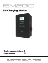
Enelion Lumina is a versatile EV charger offering 7.4kW/ 22kW charging power, LTE/4G connectivity, and RFID/NFC user authorization. It features an LED status bar, an integrated energy meter, and a user-friendly mobile app for remote control and monitoring. Its modular design allows for future upgrades and expansion, making it a scalable solution for various charging needs.

Enelion Lumina is a versatile EV charger offering 7.4kW/ 22kW charging power, LTE/4G connectivity, and RFID/NFC user authorization. It features an LED status bar, an integrated energy meter, and a user-friendly mobile app for remote control and monitoring. Its modular design allows for future upgrades and expansion, making it a scalable solution for various charging needs.

Installation
guide
LUMINA
3in1 modular structure — build and upgrade your dreamed solution using the same base module.
Quick installation — get your EV charger ready to work online in no more than 15 minutes of the installation process.
enelion.com/en/help
MODEL LB-32-3-X-0-X-XX-MRG-00
MODEL LB-32-3-X-0-X-XX-RG-00
Dear Our
Loyal Customer
Congratulations on your purchase of the Enelion charger
and thank you for your trust.
Before installing the device, please ensure
that the box contains all of the components.
The current version of the operating
and installation manual is available at:
enelion.com/en/help
Please read this manual before attempting
to install or commission the charger.
Table of content
Introduction
ENELION LUMINA products family 4
Additional tools necessary for installation 5
Features 6
Technical specications 7
Safety
Safety instructions 9
Before the installation
Planning the installation 10
Installation
Installation instructions 11
Daily use and operation
How do I charge? 17
Interface LED 18
Maintenance and cleaning 18
Practical details 19
ENELION LUMINA
products family
SOCKET - OPEN
ENELION
LUMINA
CABLE
ENELION
LUMINA
SOCKET PREMIUM
ENELION
LUMINA
SOCKET
ENELION
LUMINA
BACKPLATE
4
Additional tools
necessary for installation
x6
5
max. 5 mm 5 mm
PH2 / PH3
PZ1 / PZ2 / PZ3
T10 / T15 / T20
Features
INTERFACE LED
SPACE FOR OPTIONAL
BACKUP POWER SUPPLY
SPACE FOR OPTIONAL
230V CEE 7/3 SOCKET
SOCKET TYPE 2
RFID
SPACE FOR OPTIONAL
CERTIFIED ENERGY METER
WI-FI
LT E
6
Technical specications
Cover Resistant to weather conditions; polycarbonate housing / anodized aluminium*
Ingress protection IP54
Impact protection IK10
Flammability rating UL94-V0
Charging connector
AC Type 2 socket with safety lock (option to be locked permanently by the user),
complies with IEC 62196-2 / AC Type 2 cable range 5 m (7.4 kW)
and 7 m (22 kW)*; EN 62196-1
Residual current protection* Integrated Enelion RCMB 6 mA DC / requires additional RCDA and 40 A
overcurrent protection breaker within the circuit
Energy meter Integrated 3-phase with ±1% reading accuracy
MID Energy meter Built-in* / digital, complies with ModBus (RS485)**
User interface LED Light status bar; dedicated mobile application that connects with the EVSE via
OCPP 1.6**
Online communication module
Integrated LTE/4G modem (allows to install two microSIM cards** — one slot is
open, second is occupied by Enelion microSIM card)
WiFi 2.4 GHz b/g/n — direct access point to EVSE with functions
of HotSpot hiding and Wi-Fi connection
ISO 15118 Digital commutation of EVSE complies with ISO 15118**
V2G EVSE fully complies with the V2G requirements
OCPP EVSE Communication complies with the protocols OCPP 1.6 J and OCPP 2.0.1**
User authorization RFID/NFC — Mifare Classic / Free Charge
Dedicated mobile application that connects with the EVSE via OCPP 1.6**
7
Charging current/power 7.4 kW / 32 A / single-phase
22 kW / 32 A / 3-phase (TN earthing conguration)
Charging voltage 3 x 400 V AC / 230 V AC (±10%)
Supply voltage 3 x 400 V AC / 230 V AC (±10%) (TN / IT)
The power cord can be fed in from the top, bottom or through the back of EVSE
Other
Battery backup of the control module power supply*
Wireless communication with other Enelion EVSEs
and Enelion Energy Guard
Conguration of the station does NOT require any additional tools
Dynamic Load Balancing*
Remotely controlled schuko socket*
Temperature and humidity monitoring inside the EVSE
ModBus interface (RS485)
Operating temperature -30°C to +55°C
Max. above sea level 2000 m
Height 390 mm
Depth 133 mm
Width 155 mm
Weight Approx. 3 kg
Complies with the norms:
2014/53/EU (RED)
2011/65/EU (RoHS)
2014/30/EU (EMC)
2014/35/EU (LVD)
* optional
** shall be available from the second generation of the 3.0 EVSE
8
Safety instructions
Please read this manual before attempting to
install or commission the charger.
Safety instructions for installation
Do not carry out outdoor installation during
precipitation or strong winds if there is a risk
that water or debris may enter the device.
Carry out all operations described in this
manual after ensuring that there is no voltage
in the power cord.
This product may only be installed, repaired or
serviced by an authorised electrician.
All local, regional and national electrical
installation regulations must be observed.
Installation must not be carried out near
explosive atmospheres or in areas where there
is a risk of running water.
Risk to life from high electrical voltages.
The product must be permanently installed in
its nal location.
The product must be installed on a wall or
structure with sufcient load bearing capacity.
The clamps on the rear panel are live when the
power circuit is closed and must never come
into direct contact with anything other than
the Lumina plug-in electronics.
Lumina’s network SSID and password are
required for installation and conguration;
they can be found on the back of the charging
head.
Safety instructions for use
Never use or touch the device if it is damaged
or not functioning properly.
Always perform the recommended
maintenance, installation and any repair
work by an authorised service centre and in
accordance with local requirements.
Do not use water to extinguish a re.
Never clean the station with high pressure or
running water.
Do not immerse the station in water or other
liquids.
If the light bar on the device lights up red,
there is an error.
Never touch the contacts of the type 2
socket/plug and never insert foreign objects
into it.
Never use the charging cable if it is damaged
or if the connector is wet or dirty.
Do not use extension cables or adapters in
connection with the station.
The charging cable can only be disconnected
from the station by pulling on the plug handle,
not on the cable.
Make sure that the charging cable does not
cause a tripping or running over hazard.
Even though the station is designed to
withstand normal weather conditions, it
is recommended to protect it from direct
sunlight or exposure to extreme weather
conditions.
Do not use the station near strong
electromagnetic elds or in the immediate
vicinity of radio transmitters.
9
of the wire type terminated with collets are
recommended.
A residual current monitor (RCM) can be
integrated into the Lumina charger. This will
switch off the current to the electric vehicle if:
a residual current of 4–6 mA DC occurs. The
RCM is reset by disconnecting the charging
cable and reconnecting it.
The table above shows what charging power
you can expect from your installation.
The table is for information purposes only.
Before the
installation
This product may only be installed, repaired
or serviced by an authorised electrician.
All local, regional and national electrical
installation regulations must be observed.It
is recommended to consider future charging
needs before installation.
The power supply to the Enelion charging
terminal must be provided from an electrical
switchgear. The switchgear must have the
required protection in the form of a type B or C
overcurrent circuit breaker and a current rating
of 32 A or less, suitable for the conguration of
the device. To declare compliance with EN IEC
61851-1:2019-10, each charging point must also
be individually protected against Type A and
Type B residual current. This requirement must
be fullled by one of the following:
1. installation of a type B residual current
device (RCD B 30 mA/40 A) or RCD EV
(30 mA/40 A) in the switchgear,
2. installation of a residual current device type
A (RCD A 30 mA/40 A) in the switchgear
using the Enelion RCM B – Residual Current
Monitor type B provided on the charging
terminal.
The nal selection of the protective equipment
must be made by an authorised designer or
qualied electrician.
For maximum charging power, it is
recommended to use cables with a conductor
cross-section not exceeding 6 mm2. This
is also the maximum diameter that can be
installed in the connection terminals. For
convenient installation, exible power cords
Load Charging power
Ampere
(A)
1 phase
(kW)
3 phase
(kW)
61.4 4.1
81.6 5.5
10 2.3 6.9
13 3.0 9
16 3.7 11
20 4.6 13.8
25 5.8 1 7. 3
32 7.4 22
10
Installation
Do not carry out outdoor installation during
precipitation or strong winds if there is a risk that
water or debris may enter the device.
All of the operations described in this manual
should be carried out after making sure that there
is no voltage in the power cord.
This product may only be installed, repaired
or serviced by an authorised electrician. All
local, regional and national electrical installation
regulations must be observed.
In addition to the steps described on the
following pages, we recommend watching the
installation videos.
Preparation
01
In the box with the Lumina charger, you will nd
a template to help you choose the installation
location and prepare the installation holes.
We recommend that you position the station
so that the top edge of the charging station is
approximately 130 cm from the oor.
The electrical cable can be connected to the
station from above, from below and directly from
behind the station at the gland marked on the
template.
The design of the station allows both wall
and pole installation (additional installation
components required – sold separately). We
suggest that there is local WiFi network coverage
at the station installation site and/or LTE mobile
network coverage if the station is to be used
online.
11
enelion.com/en/help
Turn off the power before installation.
Connect the electrical cable.
Hang the mounting plate according to the
template.
Secure electric cable in the gland.
02 Electrical
connection
Installation of
mounting plate
For maximum charging power, it is recommended
to use cables with a conductor cross-section
not exceeding 6 mm2. This is also the maximum
diameter that can be installed in the connection
terminals. For convenient installation, exible
power cords of the wire type terminated with
collets are recommended.
Installation of the cables in the station cable
terminals does not require any special tools.
03
12
CAUTION! It is recommended to use the existing
colour code used in the wiring. Depending on the
standard in your country, the cable colours may
differ from those shown.
CAUTION! Before switching on the power, make
sure that the cables are connected correctly. Test
this by pulling on each wire.
After preparing the installation, close the cover.
13
02 03
Drilling holes
— inserting pins
Screwing the backplane to the wall
— tightening the cable gland
Step by step
04
01
04 05
Template leveling
— marking holes
Stripping the
insulation
from the cable
Connecting
the wires
Enelion Lumina
with optional
230V CEE
7/3 SOCKET and
optional CERTIFIED
ENERGY METER
MODEL LB-32-3-X-0-X-XX-MRG-00
MODEL LB-32-3-X-0-X-XX-RG-00
Enelion Lumina with
optional 230V CEE
7/3 SOCKET
15
06
10
07 08
09
Head
installation
Mounting the
cover with four
screws
Installing the
reector
Two long and two
short screws from
the bottom
Installation of
an alternative
head
Tightening the head
two bolts from above
Switching on the safety devices, which turns on
the voltage at the station, should be carried out
by a suitably qualied person.
Using a telephone or computer, search for the
Lumina station’s AP with the SSID listed on the
back of the charging head.
After connecting to the Lumina station’s AP with
the SSID and password given on the back of the
charging head, type the following into the address
bar of your browser: http://192.168.8.8
Access to the conguration panel is protected by
a password, which by default is: admin.
The password can be changed if necessary.
The conguration process
should be carried out
according to the instructions
on the panel.
Start-up
and conguration
of the station
05
16
http://192.168.8.8
http://192.168.8.8
Daily use
and operation 01 How do
I charge?
Before using the Lumina charger, ensure that
the following requirements are met:
An authorised electrician has made the
electrical connection correctly.
The charger is correctly congured.
The software is up to date.
If access control is congured, block it with
a registered RFID tag or disable it in the
conguration panel on the WiFi interface.
1. Before charging, check that the charging
cable and connector are not damaged or
contaminated, e.g. due to foreign objects or
water.
2. Connect the charging cable to the Lumina
charger and to the electric car. The charging
process starts and adapts automatically to
the electric car and the available power based
on its conguration. If the car does not start
charging, check that charging is enabled in
your car and that the connectors are correctly
connected.
17
The device is designed to operate in
temperatures from -30°C to 55°C. The
manufacturer does not guarantee the correct
operation of the charging station at temperatures
outside of the specied range. Chargers
damaged by temperatures below -30°C or above
55°C are not covered under the warranty.
The correct way to clean the charger is to wipe
the casing with a microbre cloth using a cleaner
dedicated to the plastic of the casing. Plastic
parts (the socket) should be cleaned with a
microbre cloth using a cleaning agent dedicated
to glass. Other cleaning methods (e.g. using
a wire brush) may damage the casing.
Damage caused by improper cleaning of the
device does not constitute grounds for warranty
claims.
Maintenance
Cleaning
03
04
The interface provides only basic operational
information, detailed information can be read
from the conguration panel.
Status Light type
Availability Green ashing
Charging (energy
transfer in progress)
Blue ashing from
inside towards the
edge
Charging (no energy
transfer)
Blue ashing
Warning/minor error
(the charger will
attempt to return to
its previous state)
Yellow ashing
Error Red ashing
Fatal error Steady red
Authorisation
User acceptance
Running from left to
right in green
User rejection Running from left to
right in red
Authorisation pending White dot moving
from left to right
18
02 Interface LED
The Lumina charging station has an LED
interface that provides the user with basic
information:
  • Page 1 1
  • Page 2 2
  • Page 3 3
  • Page 4 4
  • Page 5 5
  • Page 6 6
  • Page 7 7
  • Page 8 8
  • Page 9 9
  • Page 10 10
  • Page 11 11
  • Page 12 12
  • Page 13 13
  • Page 14 14
  • Page 15 15
  • Page 16 16
  • Page 17 17
  • Page 18 18
  • Page 19 19
  • Page 20 20
  • Page 21 21
  • Page 22 22

Enelion Lumina Installation guide

Type
Installation guide

Enelion Lumina is a versatile EV charger offering 7.4kW/ 22kW charging power, LTE/4G connectivity, and RFID/NFC user authorization. It features an LED status bar, an integrated energy meter, and a user-friendly mobile app for remote control and monitoring. Its modular design allows for future upgrades and expansion, making it a scalable solution for various charging needs.

Ask a question and I''ll find the answer in the document

Finding information in a document is now easier with AI