Tripp Lite TRIPP-LITE PV1000HF PowerVerter DC-to-AC Inverters Owner's manual

Category
Power adapters & inverters
Type
Owner's manual
1
Owner’s Manual
PowerVerter®
DC-to-AC Inverters
Models: PV1000HF, PV1800HF & PV3000HF
Input Output
12 VDC 120V, 60 Hz. AC
1111 W. 35th Street, Chicago, IL 60609 USA • tripplite.com/support
Copyright © 2022 Tripp Lite. All rights reserved.
WARRANTY REGISTRATION
Register your product today and be
automatically entered to win an ISOBAR®
surge protector in our monthly drawing!
tripplite.com/warranty
Español 14 • Français 27
Reliable AC Power Wherever You Need It!
Congratulations! You’ve purchased the most advanced, feature-rich Inverter designed as a mobile energy source for your
vehicle. PowerVerter Inverters efficiently convert DC (battery) power into 120V AC (household) power, allowing you to
use equipment you commonly use at home—appliances, entertainment systems, computers, power tools and more—while
cruising the open road or out on the open water. PowerVerter Inverters, through a high-efficiency conversion process and a
charge conservation setting, draw the highest level of performance from your batteries without overtaxing them,
lengthening their service life. An automatic low battery shutdown feature ensures you'll always have plenty of power for
starting purposes.
PV1000HF PV1800HF PV3000HF
Automatic
Overload Protection
Automatic “Battery-
Saver” Low Voltage
Shutdown
High Efficiency
DC-to-AC Inversion
Multi-Function
Lights & Switches
Optional Remote
Control Capability
(Module included with
PV3000HF)
2
Table of Contents
Important Safety Instructions 3
Feature Identification 4
Operation 5
Application Guide 7
Mounting (optional) 8
Battery Connection 9
Troubleshooting 11
Specifications 12
Service 13
Maintenance 13
Warranty and Product Registration 13
3
Important Safety Instructions
SAVE THESE INSTRUCTIONS!
This manual contains important instructions and warnings that should be followed during the installation, operation and
storage of all Tripp Lite Inverters.
Location Warnings
Install your Inverter in a location or compartment in your vehicle that minimizes exposure to heat, dust, direct sunlight
and moisture. Flooding the unit with water will cause it to short circuit and could cause personal injury due to electric
shock.
Leave a minimum of 2" clearance at front and back of the Inverter for proper ventilation. To avoid overheating the
Inverter, any compartment that contains the Inverter must be properly ventilated with adequate outside air flow. The
heavier the load of connected equipment, the more heat will be generated by the unit.
Do not install the Inverter directly near magnetic storage media, as this may result in data corruption.
Do not install near flammable materials, fuel or chemicals.
Battery Connection Warnings
Multiple battery systems must be comprised of batteries of identical voltage, age, amp-hour capacity and type.
Because explosive hydrogen gas can accumulate near batteries if they are not kept well ventilated, your batteries
should not be installed in a “dead air” compartment. Ideally, any compartment would have some ventilation to outside
air.
Sparks may result during final battery connection. Always observe proper polarity as batteries are connected.
Do not allow objects to contact the DC input terminals. Do not short or bridge these terminals together. Serious personal
injury or property damage could result.
Ground Connection Warnings
• Safe operation requires connecting the Inverter's Main Ground Lug directly to the frame of the vehicle or earth ground.
For protection against possible electrical shock hazards, if the Inverter is operated in wet or damp conditions, a user-
supplied, portable GFCI (ground fault circuit interruptor) must be connected between each Inverter receptacle and the
equipment it powers.
Equipment Connection Warnings
Do not use a Tripp Lite Inverter in life support or healthcare applications where a malfunction or failure of
a Tripp Lite Inverter could cause failure of, or significantly alter the performance of, a life support device or
medical equipment.
You may experience uneven performance results if you connect a surge suppressor, line conditioner or UPS system to
the output of the Inverter.
Operation Warnings
Your Inverter does not require routine maintenance.
Potentially lethal voltages exist within the Inverter as long as the battery supply is connected. During any service work,
the battery supply should therefore be disconnected.
• Do not connect or disconnect batteries while the Inverter is operating from the battery supply. Dangerous arcing may
result.
4
Identify the premium features on your specific model and quickly locate instructions on how to maximize their use.
1 Operating Mode Switch: controls Inverter operation.
Set this 3-position rocker switch to “ON” to have your
Inverter provide connected equipment with AC power
by converting DC power from an attached battery. Set
switch to “OFF” when not using connected equipment
to prevent battery drain. Set switch to “REMOTE” to
remotely monitor and control the Inverter with the use
of an optional remote module.
2 “LOAD” Indicator Lights: intuitive “trac light”
signals show approximate equipment load level. See
page 4 for instructions on reading indicator lights.
3 “BATTERY” Indicator Lights: intuitive “trac light”
signals show approximate charge level of your battery.
See page 4 for instructions on reading indicator lights.
4 DC Power Terminals: connect to your battery
terminals. See page 7 for connection instructions.
5 AC Receptacles: allow you to connect equipment
that would normally be plugged into a utility outlet.
PV3000HF models include two receptacles that accept
either 15- or 20-amp plugs.
6 Resettable Circuit Breaker(s): protect your Inverter
against damage due to overload. PV3000HF models
include two separate 20-amp circuits. See page 4 for
resetting instructions.
7 Remote Control Module Connector: allows remote
monitoring and control with an optional module
(Tripp Lite model APSRM4, sold separately or included
with PV3000HF models). See remote module owner’s
manual for connection instructions.
8 Battery Charge Conserver (Load Sense) Dial:
conserves battery power by setting the low-load level
at which the Inverter automatically shuts o. See page
4 for setting instructions.
9 Multi-Speed Cooling Fan(s): quiet, ecient fans
prolong equipment service life.
10 Main Ground Lug: properly grounds the Inverter to
vehicle grounding system or earth ground. See page 7
for connection instructions.
Low Battery Alarm/Shutdown (internal, not
shown): automatically detects low voltage and shuts
down Inverter to preserve vehicle battery.
Overload Alarm/Shutdown (internal, not shown):
automatically detects wattage overload on Inverter
outlets and shuts down Inverter as a protective
measure.
PV3000HF Rear Panel
PV3000HF Front Panel
PV1800HF Rear PanelPV1800HF Front PanelPV1000HF Rear PanelPV1000HF Front Panel
Feature Identification
4
8
8
8 3
3
3 7
7
7 2
2
2 1
1
1
44 1010 49 95
6 6 910 4 9
5
5 5
5
“BATTERY” Indicator Lights: These three lights will
illuminate in several sequences to show the approximate
charge level of your connected battery:
Approximate Battery Charge Level
Indicator Illuminated Battery Capacity
1 Green 91%–Full
2 Green & Yellow 81%–90%
3 Yellow 61%–80%
4 Yellow & Red 41%–60%
5 Red 21%–40%
6 Flashing Red (slowly)* 1%–20%
7 Flashing Red (quickly)** 0% (Inverter
has shutdown)
“LOAD” Indicator Lights: These three lights will illuminate
in several sequences to show the approximate equipment
load level on the Inverter’s AC receptacles.
Approximate Equipment Load Level
Indicator Illuminated Load Level
1 Green 0%-50%
2 Green & Yellow 51%-75%
3 Yellow 76%-90%
4 Red > 90%
5 Flashing Red (quickly)** OVERLOAD
(Inverter has
shutdown)
† Charge levels listed are approximate. Actual conditions vary
depending on battery condition and load. * Approximately
½ second on, ½ second off. ** Approximately ¼ second on,
¼ second off. See “Resetting Your Inverter to Restore AC Power”
to reset after Inverter shut down.
Operation
Switch Modes
Switch between the following operating modes as appropriate to your situation:
“ON”: Switch to this
setting to provide
connected equipment
with AC power.
“OFF”: Switch to
this setting to shut
down the Inverter
completely, preventing
it from drawing power
from the batteries. Use this switch to
automatically reset the unit if it shuts
down due to low battery or overload.
Use an optional remote control module
(Tripp Lite model APSRM4, sold
separately or included with PV3000HF
models) to reset unit due to overload
only.
“REMOTE”: Switch to
this setting to remotely
monitor and control the
Inverter with the use
of an optional remote
module. See remote module’s owner’s
manual for operating instructions.
Indicator Lights
Your Inverter is equipped with a simple, intuitive, user-friendly set of indicator lights. These easily-remembered “traffic
light” signals will allow you, shortly after first use, to tell at a glance the charge condition of your batteries, as well as
ascertain approximate equipment load level.
1
4
7
2
5
3
6
1
4
2
5
3
6
Operation
Resetting Your Inverter to Restore AC Power
Your Inverter may cease supplying AC power in order to protect itself from overload or to protect your electrical system. To
restore normal functioning:
Low Battery Shutdown Reset: Set operating mode switch to “OFF” and run vehicle engine to recharge battery. When
battery is adequately charged, switch operating mode switch back to either “REMOTE” or “ON.”
Overload Shutdown Reset: Set operating mode switch to “OFF” and remove some of the connected electrical load (ie:
turn off some of the AC devices drawing power which may have caused the overload of the unit). Wait one minute, then
switch operating mode switch back to either “REMOTE” or “ON.”
Output Circuit Breaker Reset (Select Models): Alternatively, check output circuit breaker(s) on the unit's front panel. If
tripped, remove some of the electrical load, then wait one minute to allow components to cool before resetting the circuit
breaker. See Troubleshooting for other possible reasons AC output may be absent.
Set Battery Charge Conserver (Load Sense) Dial
In order to save battery power, the Inverter automatically shuts off in the absence of any power demand
from connected equipment or appliances (the electrical load). When the unit detects a load, it automatically
turns on. Users may choose the minimum load the Inverter will detect by adjusting the Battery Charge
Conserver Dial (see diagram). Using a small tool, turn the dial clockwise to lower the minimum load that will
be detected, causing the Inverter to turn on for smaller loads. When the dial is turned fully clockwise, the
Inverter will operate even when there is no load. Turn the dial counterclockwise to set a higher minimum load, causing the
Inverter to stay off until the new minimum load is reached. When the dial is turned fully counterclockwise, the Inverter will
turn on when it detects any load greater than approximately 150 Watts.
Note: The factory setting for the dial is fully clockwise. However, based on the threshold load to which you’d like the Inverter to
respond, you should adjust the dial counterclockwise to reduce its sensitivity until the Inverter is active only when connected
equipment or appliances are actually in use.
Connect Remote Control—OPTIONAL
All models feature an 8-conductor telephone style receptacle on the front panel for use with an optional remote control
module (Tripp Lite model APSRM4, sold separately or included with PV3000HF models). The remote module allows
the Inverter to be mounted in a compartment or cabinet out of sight, while operated conveniently from your vehicle’s
dashboard. See instructions packed with the remote control module.
7
Application Guide
540 watts ÷ 12V = 45 DC Amps
45 DC Amps × 5 Hrs. Runtime
× 1.2 = 270 Amp-Hours
Match Battery Amp-Hour Capacity to Your Application
Select a battery or system of batteries that will provide your Inverter with proper DC voltage and an adequate amp-hour
capacity to power your application. Even though Tripp Lite Inverters are highly efficient at DC-to-AC inversion, their rated
output capacities are limited by the total amp-hour capacity of connected batteries and the support of your vehicle’s
alternator if the engine is kept running.
300W + 220W + 20W = 540W
¼" Drill Orbital Sander
Cordless Tool
Charger
300W + 140W + 100W = 540W
Blender Color TV
Laptop
Computer
• STEP 1: Determine Total Wattage Required
Add the wattage ratings of all equipment you will connect
to your Inverter. Wattage ratings are usually listed in
equipment manuals or on nameplates. If your equipment
is rated in amps, multiply that number times AC utility
voltage to determine watts. (Example: a ¼ in. drill
requires 2½ amps. 2½ amps × 120 volts = 300 watts.)
Note: Your Inverter will operate at higher efficiencies at about
75% - 80% of nameplate rating.
• STEP 2: Determine DC Battery Amps Required
Divide the total wattage required (from step 1, above)
by the battery voltage (12) to determine the DC amps
required.
• STEP 3: Estimate Battery Amp-Hours Required
(for operation unsupported by the alternator)
Multiply the DC amps required (from step 2, above)
by the number of hours you estimate you will operate
your equipment exclusively from battery power before
you have to recharge your batteries. Compensate for
inefficiency and wiring losses by multiplying this number
by 1.2. This will give you a rough estimate of how
many amp-hours of battery power (from one or several
batteries) you should connect to your Inverter.
Note: Battery amp-hour ratings are usually given for a 20-hour
discharge rate. Actual amp-hour capacities are less when
batteries are discharged at faster rates. For example, batteries
discharged in 55 minutes provide only 50% of their listed amp-
hour ratings, while batteries discharged in 9 minutes provide
as little as 30% of their amp-hour ratings.
Appliances
Example
Tools
You must allow your batteries to recharge long enough to replace the charge lost during Inverter operation or else you will
eventually run down your batteries.
Note: For Tripp Lite Inverters over 1000 watts used in mobile applications, Tripp Lite recommends you use at least two batteries, if
possible, fed by a heavy-duty alternator anytime the vehicle is running. Tripp Lite Inverters will provide adequate power for ordinary
usage within limited times without the assistance of your vehicle’s alternator. However, when operating extremely heavy electrical
loads at their peak, you may wish to “assist your batteries” by running your vehicle engine faster than normal idling.
8
Vehicular and Non-Vehicular
Horizontal Mount
Install and tighten four user-supplied fasteners through
Inverter mounting slots and into a rigid horizontal surface.
Install fasteners as far back in the mounting slots as
possible, otherwise the Inverter may slide back and forth
if fasteners loosen.
Mounting (optional)
WARNING! If you choose to mount your Inverter, mount it and wire its DC input BEFORE DC battery
connection. Failure to follow these instructions may lead to personal injury and/or damage to the
Inverter and connected systems.
Tripp Lite Inverters are designed for horizontal mounting in a variety of vehicular or non-vehicular applications. User must
supply mounting hardware and is responsible for determining if the hardware and mounting surface are suitable to support
the weight of the Inverter. Contact Tripp Lite if you require further assistance in mounting your Inverter.
9
PV1000HF
PV1800HF
Connect your Inverter to your batteries using the following procedures—always loosely twist each pair of cables
(one positive and one negative) together:
Connect DC Wiring
Connection to Two DC Terminals
PV1000HF and PV1800HF models include two DC terminals; PV3000HF models include
four DC terminals (two positive and two negative). For PV3000HF models, it is acceptable
to use only one set of cables to connect your battery to only one positive and one negative
DC terminal, however, your PV3000HF may provide reduced output power. It doesn’t make
a difference which positive and negative terminal you choose for the connection because
both positive terminals are internally bonded and both negative terminals are also internally
bonded.
Regardless of the model, you must run positive cable(s) through user-supplied UL-listed
fuse(s) and fuse block(s) of the proper size: PV1000HF—175 amp fuse, PV1800HF—250
amp fuse, PV3000HF—500 amp fuse.
See Specifications page for Minimum Recommended Cable Sizing Chart. An excellent source of
cables are battery jumper cables. Output performance will decrease if you use only one jumper
cable.
Connection to Four DC Terminals
To obtain maximum output power from PV3000HF models, it is recommended (but not
required) that you use four 00 gauge cables to connect your battery to all four DC terminals.
In this connection you must run two positive cables of equal length through two user-
supplied UL-listed 250-amp fuses and fuse blocks. Use the equivalent of two 00 cables in
all other connections within the battery system.
Length & Gauge of Cables
Although your Inverter is a high-efficiency converter of electricity, its rated output capacity is limited by the length and
gauge of the cabling running from the battery to the unit. Use the shortest length and largest diameter cabling (maximum
00 gauge) to fit your Inverter’s DC Input terminals. Shorter and heavier gauge cabling reduces DC voltage drop and
allows for maximum transfer of current. Your Inverter is capable of delivering peak wattage at up to 200% of its rated
continuous wattage output instantaneously. See Specifications page for details. Heavier gauge cabling should be used
when continuously operating heavy draw equipment under these conditions. Tighten your Inverter and battery terminals
to approximately 3.5 Newton-meters (2.58 foot lbs.) of torque to create an efficient connection and to prevent excessive
heating at this connection. Insufficient tightening of the terminals could void your warranty.
Connect Ground
Using a #8 AWG wire or larger, directly connect the Main Ground Lug to the vehicle’s chassis ground or earth ground. See
Feature Identification section to locate Main Ground Lug. All installations must comply with national and local codes and
ordinances.
Battery Connection
PV3000HF
10
Battery Connection
Connect Fuse
In addition to the protection provided by the Inverter’s internal fuses, NEC article 551 requires that you connect your
Inverter’s positive DC Terminal(s) directly to a UL-listed fuse(s) and fuse block(s) within 18 inches of the battery. See
diagrams below for proper fuse placement.
WARNING! Never attempt to operate your Inverter by connecting it directly to output from an alternator
rather than a battery or battery bank.
CAUTION! Observe proper polarity with all DC connections. Reversed polarity will cause internal
damage to your Inverter.
Vehicular
Your Inverter’s Nominal DC Input Voltage must match the voltage of your battery or batteries—12 Volts in most vehicular
applications. It is possible to connect your Inverter to the main battery within your vehicle’s electrical system. In many
vehicular contexts, the Inverter will be connected to one or more dedicated auxiliary (house) batteries which are isolated
from the drive system to prevent possible draining of the main battery.
Note: Connection to all four DC terminals is recommended to
provide the maximum output power from PV3000HF models.
1 12 Volt Alternator
2 Vehicle Battery Ground
3 12 Volt Main Battery
4 12 Volt Auxiliary (House)
Battery
5 UL-Listed Fuses & Fuse
Blocks (mounted within
18 inches of the battery)
6 Battery Isolator
7 Large Diameter Cabling,
Maximum 00 Gauge to Fit
Terminals
8 8 AWG (minimum) Ground
Wire to Vehicle Frame or Earth
Ground
12 Volt Main Battery Connection—two DC terminals
12 Volt Main and Auxiliary (House) Battery Connection (Isolated Parallel)—two DC terminals
1
1
2
2
2
3 7
7
6
8
8
4
3
5
5
Note: Connection to all four DC terminals is recommended to
provide the maximum output power from PV3000HF models.
11
Troubleshooting
Try these remedies for common Inverter problems before calling for assistance. Call Tripp Lite Customer Service at
773.869.1234 before returning your unit for service.
Operating Mode Switch
Battery Indicator Lights
Load Indicator Lights
SYMPTOM PROBLEMS CORRECTIONS
No AC Output
(All Indicator Lights Are OFF)
Operating Mode Switch is
set to “OFF.” Set Operating Mode Switch to “REMOTE” or “ON.”
User-supplied UL-listed
external DC input fuses
have blown. Replace
fuses.
Replace fuses.
Red Battery Indicator Light
Is Rapidly Flashing
(¼ Second Flashes)
Unit has shut down due to
excessive
battery discharge.
Run your engine to raise battery voltage. Check
external battery connections and fuse. Reset by moving
Operating Mode Switch to “OFF.” Wait one minute and
switch to “REMOTE” or “ON.”
If unit remains in shutdown mode after several attempts
to reset contact Tripp Lite Customer Service for
assistance.
Red Load Indicator Light
Is Rapidly Flashing
(¼ Second Flashes)
Unit has shut down due to
overload.
Reduce load. Reset by moving Operating Mode Switch
to “OFF.”
Wait one minute and switch to “REMOTE” or “ON.” If
unit remains in shutdown mode after several attempts
to reset contact Tripp Lite Customer Service for
assistance.
Connected Equipment
Experiences Audio/Video interference. Reposition equipment antennas and Inverter.
Buzzing Sound Or Picture Distortion
Inverter Output Seems
Intermittent Loose cable connections. Check and secure all connections.
12
Specifications
MODEL NUMBER: PV1000HF PV1800HF PV3000HF
Continuous Power (@ 20° C):* 1000 Watts 1800 Watts 3000 Watts
Double Boost™ Peak Surge Power:* 2000 Watts 3600 Watts 6000 Watts
DC Input Volts (Nominal): 12 VDC 12 VDC 12 VDC
DC Input Voltage Range: 10 - 15 VDC 10 - 15 VDC 10.5 - 15 VDC
DC Input Connection: User Supplied Cables User Supplied Cables User Supplied Cables
Output Volts (Nominal): 120 VAC 120 VAC 120 VAC
Output Frequency (Nominal): 60 Hz, ± 0.5% 60 Hz, ± 0.5% 60 Hz, ± 0.5%
Efficiency: Up to 94% Up to 94% Up to 94%
Output Waveform: Modified Sine Wave Modified Sine Wave Modified Sine Wave
* DoubleBoost duration (instantaneous). Actual output depends on battery age, battery charge level and ambient temperature.
Minimum Recommended Cable Sizing Chart
Always loosely twist each pair of cables (one positive and one negative) together. Use in conjunction with DC wiring
connection instructions in the Battery Connection section. Using 4 conductors is recommended (but not required) to
obtain maximum output power from PV3000HF models.
Wire Gauge
2 Conductors (all models) 4 Conductors (PV3000HF only)
Watts 6 4 2 0 00 Twin 00
500 15 ft 25 ft 39 ft 62 ft 79 ft 158 ft
700 11 ft 18 ft 28 ft 44 ft 56 ft 112 ft
1000 N/R 12 ft 20 ft 31 ft 39 ft 78 ft
2000 N/R N/R N/R 16 ft 20 ft 40 ft
2400 N/R N/R N/R 13 ft 16 ft 32 ft
3000 N/R N/R N/R 10 ft 13 ft 26 ft
† N/R = Not Recommended. NOTE: Acceptable power is directly related to cable length (i.e. - the shorter the cable, the better the
performance)
Tripp Lite Inverters include a Battery Charge Conserver (Load Sense) Control which saves battery power by
allowing users to set the minimum load level at which the unit’s inverter turns on. Users can significantly
reduce the No Load DC Input Current to a very low amperage power level with the use of this control.
13
1111 W. 35th Street, Chicago, IL 60609 USA • tripplite.com/support
22-02-006 932283_RevD
Tripp Lite warrants its Inverters to be free from defects in materials and workmanship for a period of one year (domestic) or 120 days (export) from the
date of retail purchase by end user.
Tripp Lite’s obligation under this warranty is limited to repairing or replacing (at its sole option) any such defective products. To obtain service under this
warranty you must obtain a Returned Material Authorization (RMA) number from Tripp Lite or an authorized Tripp Lite service center. Products must be
returned to Tripp Lite or an authorized Tripp Lite service center with transportation charges prepaid and must be accompanied by a brief description of
the problem encountered and proof of date and place of purchase. This warranty does not apply to equipment which has been damaged by accident,
negligence or misapplication or has been altered or modified in any way, including opening of the unit’s casing for any reason. This warranty applies only
to the original purchaser who must have properly registered the product within 10 days of retail purchase.
EXCEPT AS PROVIDED HEREIN, TRIPP LITE MAKES NO WARRANTIES, EXPRESS OR IMPLIED, INCLUDING WARRANTIES OF
MERCHANTABILITY AND FITNESS FOR A PARTICULAR PURPOSE. Some states do not permit limitation or exclusion of implied warranties; therefore,
the aforesaid limitation(s) or exclusion(s) may not apply to the purchaser.
EXCEPT AS PROVIDED ABOVE, IN NO EVENT WILL TRIPP LITE BE LIABLE FOR DIRECT, INDIRECT, SPECIAL, INCIDENTAL OR
CONSEQUENTIAL DAMAGES ARISING OUT OF THE USE OF THIS PRODUCT, EVEN IF ADVISED OF THE POSSIBILITY OF SUCH DAMAGE.
Specifically, Tripp Lite is not liable for any costs, such as lost profits or revenue, loss of equipment, loss of use of equipment, loss of software, loss of
data, costs of substitutes, claims by third parties, or otherwise.
PRODUCT REGISTRATION
Visit tripplite.com/warranty today to register your new Tripp Lite product. You’ll be automatically entered into a drawing for a chance to win a FREE
Tripp Lite product!
** No purchase necessary. Void where prohibited. Some restrictions apply. Open to U.S. residents only. See tripplite.com for details.
Tripp Lite has a policy of continuous improvement. Specifications are subject to change without notice. Photos and illustrations may differ slightly from
actual products.
If you are returning your Inverter to Tripp Lite, please pack it carefully, using the ORIGINAL PACKING MATERIAL that
came with the unit. Enclose a letter describing the symptoms of the problem. If the Inverter is within the warranty period,
enclose a copy of your sales receipt. To obtain service you must obtain a Returned Material Authorization (RMA) number
from Tripp Lite or an authorized Tripp Lite service center.
Your Inverter requires no maintenance and contains no user-serviceable or replaceable parts, but should be kept dry at all
times. Periodically check, clean and tighten all cable connections, as necessary, both at the unit and at the battery.
Service
Maintenance
Warranty and Product Registration
14
Manual del Propietario
Inversores de CD a CA
PowerVerter®
Modelos: PV1000HF, PV1800HF y PV3000HF
Entrada Salida
12 VCD 120V, 60 Hz. CA
1111 W. 35th Street, Chicago, IL 60609 EE UU • tripplite.com/support
Copyright © 2022 Tripp Lite. Todos los derechos reservados.
English 1 • Français 27
¡Confiable Energía CA en Donde la Necesite!
¡Felicidades! Ha comprado el inversor más avanzado, con grandes características, diseñado como una fuente de
energía móvil para su vehículo. Los inversores PowerVerter convierten eficientemente energía de CD (batería) en
energía de 120V CA (doméstica), permitiéndole usar el equipo que usted usa normalmente en el hogar
(electrodomésticos, sistemas de entretenimiento, computadoras, herramientas eléctricas y más) mientras se desplaza en
carretera o aguas adentro, Los inversores PowerVerter, a través de un proceso de conversión de alta eficiencia y una
configuración de conservación de carga, extraen el más alto nivel de rendimiento de sus baterías sin sobrecargarlas,
prolongando su vida útil. Una función de apagado automático por batería baja le asegura que siempre tendrá suficiente
energía para arrancar.
PV1000HF PV1800HF PV3000HF
Protección
Automática contra
Sobrecargas
Apagado
Automático de la
Batería por Voltaje
Bajo "Protector de
Batería"
Inversión de CD a
CA de Alta
Eficiencia
Luces e
Interruptores
Multifunción
Capacidad de
Control Remoto
Opcional
(Módulo incluido con
PV3000HF)
15
Índice
Instrucciones de Seguridad Importantes 16
Identificación de Características 17
Operación 18
Guía de Aplicación 20
Instalación (opcional) 21
Conexión de la Batería 22
Solución de Problemas 24
Especificaciones 25
Servicio 26
Mantenimiento 26
Garantía 26
16
Instrucciones de Seguridad Importantes
¡CONSERVE ESTAS INSTRUCCIONES!
Este manual contiene instrucciones y advertencias importantes que deben seguirse durante la instalación, operación y
almacenamiento de todos los Inversores de Tripp Lite.
Advertencias para la Ubicación
Instale su Inversor en una ubicación o compartimiento en su vehículo que minimice la exposición al calor, polvo, luz
solar directa y humedad. Inundar la unidad con agua causará un corto circuito y podría causar lesiones personales
debido a una descarga eléctrica.
Deje un espacio libre de 5 cm [2"] como mínimo al frente y en la parte posterior del Inversor para una ventilación
adecuada. Para evitar sobrecalentar al Inversor, debe ventilarse adecuadamente cualquier compartimiento que
contenga el Inversor con un flujo adecuado de aire exterior. Mientras más pesada sea la carga del equipo conectado,
mayor será el calor generado por la unidad.
No instale el Inversor directamente cerca de medios de almacenamiento magnético, ya que puede causar la corrupción
de la información.
No lo instale cerca de materiales inflamables, combustibles o químicos.
Advertencias para la Conexión de la Batería
Los sistemas de múltiples baterías deben componerse de baterías de voltaje, edad, capacidad en amperes-hora y tipo
idénticos.
Debido que cerca de las baterías puede acumularse hidrógeno explosivo si no se mantienen bien ventiladas, sus
baterías no deben instalarse en compartimientos sin circulación de aire. En forma ideal, cualquier compartimiento
debería tener algo de ventilación para el aire exterior.
Durante la conexión final de la batería pueden producirse chispas. Observe siempre la polaridad correcta al conectar
las baterías.
No permita objetos que hagan contacto con las terminales de entrada de CD. No ponga en corto o puentee las
terminales entre sí. Puede ocasionar lesiones personales graves o daños a la propiedad.
Advertencias sobre la Conexión a Tierra
• La operación segura requiere que conecte el poste principal de conexión a tierra del inversor directamente al bastidor
del vehículo o a tierra física.
Para protección contra posibles peligros de descargas eléctricas, si el inversor está operado en condiciones húmedas,
debe conectarse entre cada tomacorrientes del inversor y el equipo que alimenta un GFCI (interruptor de circuito por
falla a tierra) portátil suministrado por el usuario.
Advertencias en relación con la Conexión del Equipo
No utilice un Inversor de Tripp Lite en aplicaciones de soporte de vida o de cuidado de la salud en que una
falla de un Inversor de Tripp Lite pudiera causar fallas o alterar significativamente el funcionamiento de un
dispositivo de soporte de vida o equipo médico.
Usted puede experimentar un funcionamiento irregular si conecta un supresor de sobretensiones, acondicionador de
línea o sistema UPS a la salida de su inversor.
Advertencias de Operación
Su inversor no requiere mantenimiento de rutina.
Dentro del inversor existen voltajes potencialmente peligrosos en tanto la alimentación por batería esté activa. Por lo
tanto, durante cualquier trabajo de mantenimiento, debe desconectarse la alimentación por batería.
• No conecte o desconecte las baterías mientras el inversor esté funcionando alimentado por batería. Puede producirse
un arco peligroso.
17
Identifique las características premium en su modelo específico y rápidamente ubique las instrucciones de cómo
maximizar su uso.
1
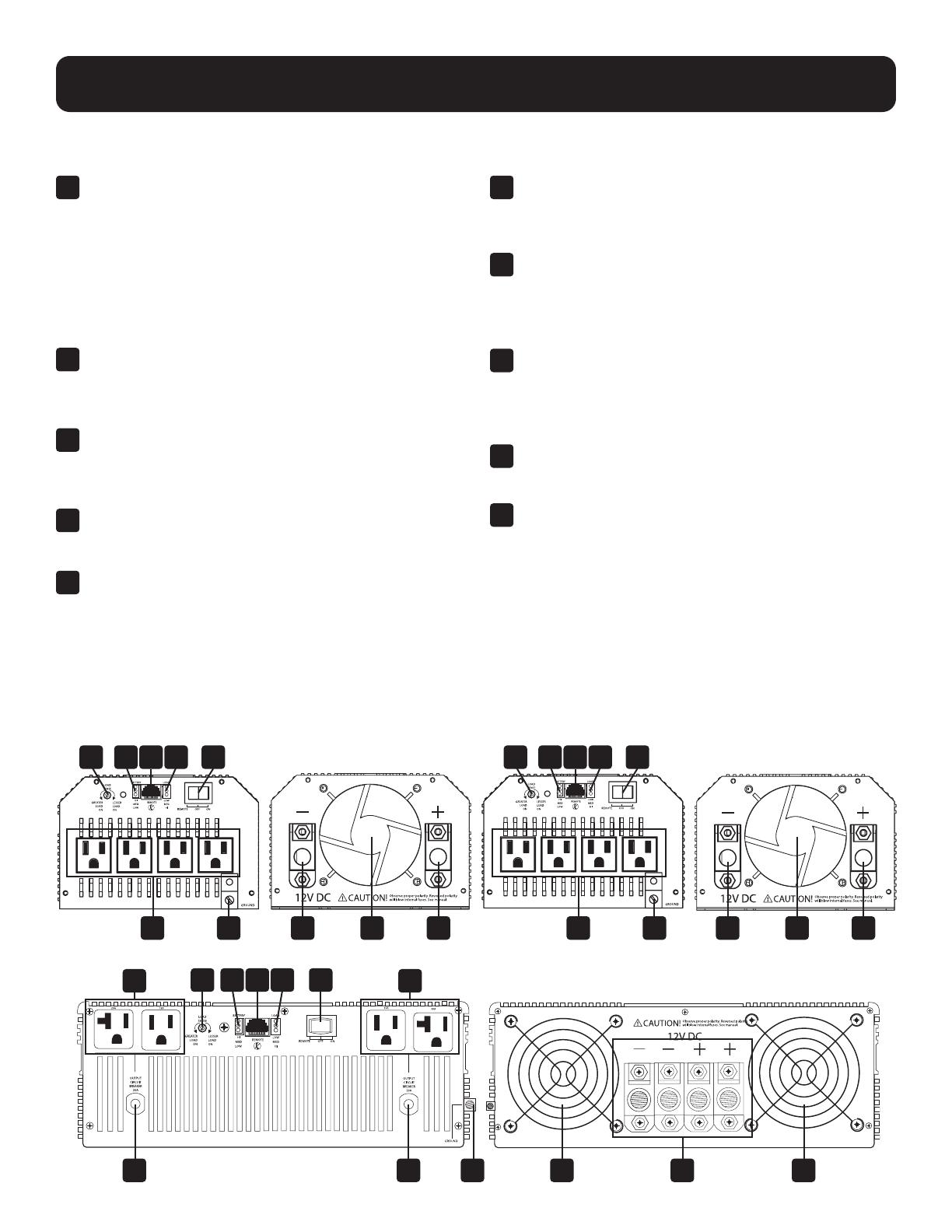
Switch de Modo de Operación: Controla el
funcionamiento del inversor. Coloque este switch de
3 posiciones en “ON” para que su inversor alimente al
equipo conectado con energía CA al convertir energía
CD de una batería conectada. Coloque el switch en
“OFF” cuando no se use el equipo conectado para
evitar la descarga de la batería. Coloque el selector en
“REMOTE” para monitorear y controlar en forma remota
el inversor con el uso de un módulo remoto opcional.
2 Luces Indicadoras “LOAD”: Las señales intuitivas
tipo “semáforo” muestran el nivel aproximado de carga
del equipo. Para ver las instrucciones sobre la lectura
de las luces indicadoras, consulte la página 4.
3
Luces Indicadoras “BATTERY”: Las señales intuitivas
tipo “semáforo” muestran el nivel aproximado de carga
de su batería. Para ver las instrucciones sobre la
lectura de las luces indicadoras, consulte la página 4.
4 Terminales de Alimentación CD: Conecte a las
terminales de su batería. Para instrucciones de
conexión, consulte la página 7.
5 Tomacorrientes de CA: Le permiten conectar
equipo que normalmente sería enchufado en un
tomacorriente de la red pública. Los modelos
PV3000HF incluyen dos tomacorrientes que aceptan
clavijas de 15 o 20 amperes.
6 Breakers Restaurables: Protegen su inversor contra
daños por sobrecarga. Los modelos PV3000HF
incluyen dos circuitos separados de 20 amperes. Para
instrucciones de restauración, consulte la página 4.
7 Conector del Módulo de Control Remoto: Permite
monitoreo y control remoto con un módulo opcional
(Tripp Lite modelo APSRM4, vendido por separado o
incluido con modelos PV3000HF). Para instrucciones
de conexión, consulte el manual del propietario.
8 Carátula del Conservador de Carga de Batería
(Detector de Carga) : Conserva la energía de la
batería congurando el nivel de carga bajo por medio
del cual el inversor se apaga automáticamente Para
instrucciones de conguración, consulte la página 4.
9 Ventilador(es) para Enfriamiento de Varias
Velocidades: Ventiladores silenciosos y ecientes
alargan la vida útil del equipo.
10 Poste de Conexión a Tierra: Conecta
apropiadamente a tierra física el inversor al sistema
de conexión a tierra del vehículo o tierra física. Para
instrucciones de conexión, consulte la página 7.
Alarma y Apagado por Batería Baja (interno, no
se muestra): Detecta automáticamente bajo voltaje y
apaga el inversor para preservar la batería del vehículo.
Alarma de Sobrecarga y Apagado (interno, no se
muestra): Detecta automáticamente sobrecarga en
Watts en los tomacorrientes del inversor y apaga el
inversor como una medida de protección.
Panel Posterior del PV3000HF
Panel Frontal del PV3000HF
Panel Posterior del PV1800HFPanel Frontal del PV1800HF
Panel Posterior del PV1000HF
Panel Frontal del PV1000HF
Identificación de Características
4
8
8
8 3
3
3 7
7
7 2
2
2 1
1
1
44 1010 49 95
6 6 910 4 9
5
5 5
18
Luces Indicadoras “BATTERY”: Estas tres luces se
iluminarán en varias secuencias para mostrar el nivel
aproximado de carga de su batería conectada:
Nivel Aproximado de Carga de la Batería
Indicador Iluminado Capacidad de la Batería
1 Verde 91%–Llena
2 Verde y Amarillo 81%–90%
3 Amarillo 61%–80%
4 Amarillo y Rojo 41%–60%
5 Rojo 21%–40%
6
Rojo Destellando (lentamente)* 1%–20%
7
Rojo Destellando (rápidamente)**
0%
(el inversor
se ha apagado)
Luces Indicadoras “LOAD”: Estas tres luces se
iluminarán en varias secuencias para mostrar el nivel
aproximado de carga del equipo en los tomacorrientes de
CA del inversor.
Nivel Aproximado de Carga del Equipo
Indicador Iluminado Nivel de Carga
1 Verde 0%-50%
2 Verde y Amarillo 51%-75%
3 Amarillo 76%-90%
4 Rojo > 90%
5 Rojo Destellando
SOBRECARGA
(rápidamente)** (El inversor se
ha apagado)
† Los niveles de carga listados son aproximados.
Las condiciones reales varían dependiendo de la condición y
carga de la batería. * Aproximadamente ½ segundo encendido,
½ segundo apagado. ** Aproximadamente ¼ segundo
encendido, ¼ segundo apagado. Vea “Restauración de Inversor
para Restaurar la Energía de CA” para restaurar después de que
el inversor se apague.
Operación
Interruptor de Modos
Alterne entre los siguientes modos de operación según corresponda a su situación:
“ON”: Cambie a esta
configuración para
alimentar al equipo
conectado con energía
de CA.
“OFF”: Cambie a esta
configuración para
apagar completamente
el inversor, evitando
que tome energía de
las baterías. Use este switch para
restablecer automáticamente la unidad
si se apaga debido a batería baja o
sobrecarga. Use un módulo de control
remoto opcional (Modelo APSRM4
de Tripp Lite, vendido por separado o
incluido con los modelos PV3000HF)
para restablecer la unidad debido a
sobrecarga solamente.
“REMOTE”: Cambie a
esta configuración para
monitorear y controlar
en forma remota el
inversor con el uso
de un módulo remoto opcional. Para
instrucciones de operación, consulte
el manual del propietario del módulo.
Luces Indicadoras
Su inversor está equipado con un juego de luces indicadoras simple, intuitivo y fácil de usar. Estas señales tipo
“semáforo” fácil de recordar le permitirán, poco después del primer uso, saber de un vistazo la condición de carga de sus
baterías, así como determinar el nivel aproximado de carga del equipo.
1
4
7
2
5
3
6
1
4
2
5
3
19
Operación
Restauración de Inversor para Restaurar la Energía de CA
Su inversor puede dejar de suministrar energía de CA a fin de protegerse contra sobrecarga o proteger su sistema eléctrico.
Para restablecer el funcionamiento normal:
Restauración de Apagado por Batería Baja: Establece el switch de modo de operación en “OFF” y opera el motor del
vehículo para recargar la batería. Cuando la batería esté correctamente cargada, cambie el modo de operación nuevamente
a “REMOTE” u “ON”.
Restauración de Apagado por Sobrecarga: Coloque el switch de modo de operación a “DC OFF” y retire algo de la
carga eléctrica conectada (i.e.: apague algunos de los dispositivos de CA que toman energía que pueden haber causado la
sobrecarga de la unidad). Espere un minuto y regrese el switch de Modo de operación nuevamente a “REMOTE” u “ON”.
Restauración del Breaker de Salida (Modelos Selectos): Alternativamente, compruebe el breaker de salida en el panel
frontal de la unidad. Si se disparó, retire algo de la carga eléctrica, espere un minuto para permitir el enfriamiento de los
componentes antes de restaurar el breaker. Para ver otras posibles razones adicionales por las que puede no haber salida
de CA, consulte Solución de Problemas.
Seleccione Carátula del Conservador de Carga de la Batería (Detección de la Carga)
A fin de ahorrar energía de la batería, el inversor se apaga en ausencia de cualquier demanda de energía
de equipo o aparatos conectados (la carga eléctrica). Cuando la unidad detecta una carga, se enciende
automáticamente. Los usuarios pueden elegir la carga mínima que detectará el Inversor ajustando la Carátula
del Conservador de Carga de la Batería (ver diagrama). Usando una herramienta pequeña, gire el dial en
sentido de las manecillas del reloj para reducir la carga mínima que se detectará, causando que el inversor se
encienda para cargas más pequeñas. Cuando la carátula se gira completamente en el sentido de las manecillas del reloj, el
inversor funcionará aún cuando no haya carga. Gire la carátula en sentido opuesto a las manecillas del reloj para establecer
una mayor carga mínima, haciendo que el inversor permanezca apagado hasta que se alcance la nueva carga mínima.
Cuando la carátula esté girada completamente en sentido opuesto al de las manecillas del reloj, el inversor se encenderá
cuando detecte cualquier carga superior a aproximadamente 150 Watts.
Nota: La configuración de fábrica para la carátula es completamente en sentido de las manecillas del reloj. Sin embargo, basado en la
carga de umbral al que desea que el inversor responda, debe ajustar la carátula en sentido opuesto al de las manecillas del reloj para
reducir su sensibilidad hasta que el inversor esté activo solo cuando aparatos o equipos conectados están realmente en uso.
Conecte el Control Remoto—OPCIONAL
Todos los modelos cuentan con un conector de estilo telefónico de 8 conductores en el panel frontal para usarse con un
módulo opcional de control remoto (Tripp Lite modelo APSRM4, vendido por separado o incluido con el modelo PV3000HF).
El módulo remoto permite al Inversor ser instalado fuera de la vista en un compartimiento o gabinete, mientras se opera
cómodamente desde el tablero de su vehículo. Consulte las instrucciones empacadas con el módulo de control remoto.
20
Guía de Aplicación
540 Watts ÷ 12V = 45 amperes de CD
45 Amperes de CD × 5 h Autonomía
× 1.2 = 270 Amperes Hora
Haga Coincidir la Capacidad en Amperes Hora con su Aplicación
Seleccione una batería o sistema de baterías que suministrarán a su inversor con voltaje de CD adecuado y una
capacidad de Amperes hora apropiada para alimentar a su aplicación. Aunque los inversores de Tripp Lite son muy
eficiente en la inversión de CD a CA, sus capacidades de salida están limitadas por la capacidad total en amperes hora
de las baterías conectadas y la asistencia del alternador de su vehículo si el motor se mantiene funcionando.
300W + 220W + 20W = 540W
Taladro de
¼"
Lijadora
Orbital
Cargador Inalámbrico
para Herramientas
300W + 140W + 100 W = 540W
Licuadora
Televisor de
Color Laptop
• PASO 1; Determine la Potencia Total en Watts
Requerida
Sume las especificaciones de potencia en Watts de todo el
equipo que conectará a su Inversor. Las especificaciones
de potencia (en Watts) están normalmente señaladas
en los manuales de los equipos o en las placas de
identificación. Si su equipo está especificado en amperes,
multiplique ese número por el valor del voltaje de CA del
suministro para determinar los Watts. (Ejemplo: un taladro
de 1/4" requiere 2.5 Amperes. 2.5 Amperes × 120 Volts =
300 Watts.)
Nota: Su Inversor funcionará a una mayor eficiencia en
aproximadamente 75% ~ 80% de la especificación de la placa de
identificación.
• PASO 2: Determine los Amperes de Batería de CD
Requeridos
Para determinar los amperes de CD requeridos, divida la
potencia total requerida (del paso 1, arriba) entre el voltaje
de la batería (12V).
• PASO 3: Calcule los amperes hora requeridos de la
batería (para operación no soportada por el alternador)
Multiplique los amperes de CD requeridos (del paso 2,
anterior) por el número de horas que estime operará su
equipo exclusivamente con energía de la batería antes de
recargar sus baterías. Compense la ineficiencia y pérdidas
del cableado multiplicando este número por 1.2. Esto le
dará un estimado aproximado de cuántos amperes hora
de energía de la batería (de una o varias baterías) debe
conectar a su Inversor.
Nota: Las especificaciones de Amperes Hora de la batería se
dan normalmente para una tasa de descarga de 20 horas. Las
capacidades reales en Amperes Hora son menores cuando las
baterías se descargan a tasas más rápidas. Por ejemplo, las
baterías descargadas en 55 minutos proporcionan sólo el 50%
de sus Amperes Hora especificados, mientras que baterías
descargadas en 9 minutos proporcionan tan solo como el 30% de
su Amperes Hora especificados.
Electrodomésticos
Ejemplo
Herramientas
Debe permitir que sus baterías se recarguen por suficiente tiempo para reponer la carga perdida durante la operación del
inversor de lo contrario finalmente agotará sus baterías.
Nota: Para inversores de Tripp Lite de más de 1000 Watts usados en aplicaciones móviles, Tripp Lite le recomienda usar al menos
dos baterías, si es posible, alimentadas por un alternador para servicio pesado en cualquier momento en que el vehículo esté
funcionando. Los inversores de Tripp Lite proporcionarán energía adecuada para uso normal en tiempos limitados sin la asistencia del
alternador de su vehículo. Sin embargo, al operar cargas eléctricas extremadamente pesadas al máximo, puede querer "ayudar a sus
baterías" operando su motor de vehículo más rápido que la velocidad normal en reposo.
  • Page 1 1
  • Page 2 2
  • Page 3 3
  • Page 4 4
  • Page 5 5
  • Page 6 6
  • Page 7 7
  • Page 8 8
  • Page 9 9
  • Page 10 10
  • Page 11 11
  • Page 12 12
  • Page 13 13
  • Page 14 14
  • Page 15 15
  • Page 16 16
  • Page 17 17
  • Page 18 18
  • Page 19 19
  • Page 20 20
  • Page 21 21
  • Page 22 22
  • Page 23 23
  • Page 24 24
  • Page 25 25
  • Page 26 26
  • Page 27 27
  • Page 28 28
  • Page 29 29
  • Page 30 30
  • Page 31 31
  • Page 32 32
  • Page 33 33
  • Page 34 34
  • Page 35 35
  • Page 36 36
  • Page 37 37
  • Page 38 38
  • Page 39 39
  • Page 40 40

Tripp Lite TRIPP-LITE PV1000HF PowerVerter DC-to-AC Inverters Owner's manual

Category
Power adapters & inverters
Type
Owner's manual

Ask a question and I''ll find the answer in the document

Finding information in a document is now easier with AI