Hargrove HGRGCI User guide

Category
Fireplaces
Type
User guide

The Hargrove HGRGCI vent-free gas log set offers a cozy and efficient heating solution for your home. Designed for use in masonry or factory-built fireplaces, this set operates as an unvented room heater, providing supplemental warmth without the need for a chimney. Its realistic log design and dancing flames create a captivating ambiance, enhancing the aesthetics of your living space. Installation must be performed by qualified professionals to ensure safety and proper operation. Enjoy the convenience and warmth of the Hargrove HGRGCI gas log set in your fireplace.

The Hargrove HGRGCI vent-free gas log set offers a cozy and efficient heating solution for your home. Designed for use in masonry or factory-built fireplaces, this set operates as an unvented room heater, providing supplemental warmth without the need for a chimney. Its realistic log design and dancing flames create a captivating ambiance, enhancing the aesthetics of your living space. Installation must be performed by qualified professionals to ensure safety and proper operation. Enjoy the convenience and warmth of the Hargrove HGRGCI gas log set in your fireplace.

INSTALLATION AND OPERATION GUIDE FOR VF
HARGROVE VENT FREE GAS LOGS
CIMARRON TIMBERS
DESIGN CERTIFIED to
UNVENTED ANSI Z21.11.2
VENTED - ANSI Z21.60/CGA 2.26
Installation and service must be provided by a qualified installer, service agency or the gas supplier.
NOTE: ADEQUATE FIREPLACE VENTILATION IS REQUIRED FOR SAFETY.
READ INSTRUCTIONS FULLY BEFORE INSTALLING OR OPERATING.
INSTALLER: LEAVE THIS MANUAL WITH THE APPLIANCE.
CONSUMER: RETAIN THIS MANUAL FOR FUTURE REFERENCE.
This appliance operates as an unvented room
heater when fitted to a solid fuel burning
masonry fireplace or UL 127 approved factory
built fireplace with the flue damper closed. It
may also be installed in an approved
unvented fireplace.
WARNING:
THIS IS AN UNVENTED GAS FIRED HEATER.
IT USES AIR (OXYGEN) FROM THE ROOM IN
WHICH IT IS INSTALLED. PROVISIONS FOR
ADEQUATE COMBUSTION AND
VENTILATION AIR MUST BE PROVIDED.
REFERENCE FUEL GAS CODE NFPA 54, ANSI
Z223.1 REFER TO PAGE 2 OF THE
INSTALLATION INSTRUCTIONS.
This appliance is designed to supplement a
current heating system. It is not designed to
be used as a primary heat source.
NOTE:
This appliance is only for use with the type of gas
indicated on the rating plate. This appliance is not
convertible for use with other gases. Solid-fuels
shall not be burned in a fireplace where a
decorative appliance is installed.
REV 122321
WARNING:
If the information in this manual is not followed
exactly, a fire or explosion may result, causing
property damage, personal injury, or loss of life.
WHAT TO DO IF YOU SMELL GAS
1.
Open a window.
2.
Do not try to light any appliance.
3.
Do not touch any electrical switch; do not use the
phone in your building.
4.
Immediately call your gas supplier from a
neighbor’s phone. Follow the gas supplier’s
instructions.
5.
If you cannot reach your gas supplier, call the fire
department.
FOR YOUR SAFETY
Do not store or use gasoline or other flammable
vapors and liquids in the vicinity of this or any other
appliance.
IMPORTANT:
Installation and service must be performed by a
qualified professional installer, service agency, or the
gas supplier. Improper installation, adjustments,
alteration, service, or maintenance can cause
personal injury or property damage. Refer to this
manual.
IMPORTANT PRE-INSTALLATION AND FIREPLACE SAFETY INFORMATION
To determine the safest and most efficient location for your Vent Free Fireplace, you must
take into consideration the following guidelines.
1.
This appliance operates as an unvented room heater certified under ANSI Z21.11.2a when fitted to a masonry
or factory built fireplace with the flue damper open or closed. It may also be installed in approved vent free fireplace.
If installing in an approved vent free firebox, refer to their instruction guide for proper installation. Solid fuels shall not
be burned in a fireplace where an unvented room heater is installed.
2.
Do not use a natural gas set for propane or a propane set for natural gas. If the gas type is not correct. DO
NOT INSTALL. Contact your dealer for immediate assistance. Any change to this heater or its controls can be
dangerous.
3.
Gas log sets must be installed by personnel qualified for installing gas appliances.
4.
The location must allow for proper clearances for accessibility of servicing and proper operation (see section
on Fireplace Clearances page 4).
5.
Consider a location where heat output would not be affected by drafts, air conditioning ducts, windows or
doors. Do not allow fans to blow directly into the fireplace, avoid any drafts that alter burner flame patterns.
6.
Inspect area surrounding the location chosen for the fireplace for possible air drafts that may affect the flames
and possibly cause sooting. Air drafts may be caused by a ceiling fan near the fireplace, a hot furnace or an open
door.
7.
Due to high temperatures, the appliance should be located out of traffic and away from furniture and
draperies. Young children should be carefully supervised when they are in the same room with the appliance. It is
recommended that adults be present when this gas appliance is operating. It is recommended that this unit is not left
burning when unattended or while anyone is sleeping.
8.
Children and adults should be alerted to the hazards of high surface temperatures and should stay away to
avoid burns or clothing ignition.
9.
Install in an area providing adequate combustion and ventilation air (see section on adequate combustion and
ventilation air requirements page 2).
10.
Do not install in a building that is of unusually tight construction. Unusually tight construction is defined as
construction where:
a.
Walls and ceiling exposed to the outside atmosphere have a continuous wall vapor retarder with a rating of 1
perm or less with openings gasketed or sealed, and
b.
Weather stripping has been added on openable windows and doors, and
c.
Caulking or sealants are applied to areas such as joints around window and door frames, between sole plates
and floors, between wall-ceiling joints, between wall panels, at penetration for plumbing, electrical and gas lines and
at other openings.
11.
Do not install this heater in bedrooms, bathrooms or recreational vehicles.
12.
This appliance may be installed in an aftermarket manufactured (mobile) home, where not prohibited by state
or local codes.
13.
Maintain adequate clearances around air openings.
14.
When glass fireplace doors are used, always operate gas log set with the doors fully open to allow for proper
combustion air and to keep control valves from overheating.
15.
Keep appliance area clear and free from combustible materials, gasoline and other flammable vapors and
liquids. Do not allow clothing or flammable materials on or near the fireplace. The flame in this appliance is not
isolated from the air space it heats and it will ignite flammable vapors, dust particles or other combustible materials
that come in contact with it which can result in an explosion or fire.
2
PREINSTALLATION REUIREMENTS
COMBUSTION AND VENTILATION AIR REQUIREMENT WORKSHEET
WARNING: IF THE AREA IN WHICH THE HEATER MAY BE OPERATED IS SMALLER THAN
THAT DEFINED AS UNCONFINED SPACE OR IF THE BUILDING IS OF UNUSUALLY TIGHT
CONSTRUCTION, PROVIDE ADEQUATE COMBUSTION AND VENTILATION AIR BY ONE OF
THE METHODS DESCRIBED IN THE NATIONAL FUEL GAS CODE, ANSI Z223.1 SECTION 5.3
OR APPLICABLE LOCAL CODES.
This heater shall not be installed in a confined space or unusually tight construction unless provisions are
provided for adequate combustion and ventilation air.
The following formula can be used to determine the maximum BTU rating per the definition of unconfined space:
STEP ONE: DETERMINE THE VOLUME OF SPACE IN CUBIC FEET.
LENGTH X WIDTH X HEIGHT = cu. Ft.
(Include adjoining rooms with doorless passageways or ventilation grills between rooms.)
Example: 24’ (L) X 16’ (W) X 8’ (H) = 3,072. cu. Ft.
STEP TWO: MULTIPLY THE VOLUME OF SPACE BY 20 BTU/Hr. TO DETERMINE THE MAXIMUM BTU/Hr.
THE SPACE CAN SUPPORT.
Example: 3,072 cu. Ft. X 20 BTU/Hr. = 61,440 BTU/Hr.
(Maximum BTU/Hr. the room can support)
STEP THREE: ADD THE BTU/Hr. OF ALL THE FUEL BURNING APPLIANCES IN THE SPACE.
VENT FREE HEATER BTU/Hr.
GAS APPLIANCE #1 BTU/Hr.
GAS APPLIANCE #2 BTU/Hr.
Example: VENT FREE HEATER 26,000 BTU/Hr.
GAS APPLIANCE #1 35,000 BTU/Hr.
TOTAL 61,000 BTU/Hr.
NOTE: DO NOT INCLUDE DIRECT-VENT GAS APPLIANCES. DIRECT VENT IS SEALED
COMBUSTION AND DRAWS COMBUSTION AIR FROM THE OUTDOORS.
THE SPACE IN THE ABOVE EXAMPLE IS AN UNCONFINED SPACE BECAUSE THE 61,000 BTU’S AN HOUR
USAGE IS LESS THATN THE 61,440 BTU’S AN HOUR AVAILABLE. IF THE TOTAL BTU’S AN HOUR USAGE IS
GREATER THAN 61,440 BTU’S AN HOUR THEN THE SPACE WOULD BE A CONFINED SPACE AND ADDITIONAL
AIR MUST BE PROVIDED.
The National Fuel Gas Code defines a confined space as a space whose volume is less than 50
cubic feet per 1,000 BTU per hour (4.8 m3 per kw) of the aggregate input rating of all appliances
installed in that space and unconfined space as a space whose volume is not less than 50 cubic
feet per 1,000 BTU per hour (4.8 m3 per kw) of the aggregate input rating of all appliances
installed in that space. Rooms communicating directly with the space in which the appliances are
installed, through openings not furnished with doors, are considered a part of the unconfined
space.
3
PREINSTALLATION SPECIFICATIONS
BTU RATINGS AND PRESSURE REQUIREMENTS
When operating the main burner, use the control knob to raise and lower the min. and max. heat
output. Turn the control knob counterclockwise for max. heat and clockwise for min heat.
Input ratings are shown in BTU per hour and are for elevations up to 2,000 feet. For elevations
above 2,000 feet, input ratings should be reduced 4% for each 1,000 feet above sea level. Refer
to the National Fuel Gas Code.
WARNING: OPERATION OF THIS APPLIANCE ON GASES FOR WHICH IT IS NOT
EQUIPPED MAY LEAD TO CARBON MONOXIDE POISONING.
FIREPLACE DIMENSIONS AND CLEARANCES
Refer to the following charts to determine the proper size set for your fireplace.
Rear Width
Depth
Front Width
*At depth listed
4
LOG SET SIZE
GAS TYPE
MAX. HEAT INPUT (BTU/Hr.)
GAS INLET PRESSURE
MAX.
MIN.
REGULATOR PRESSURE
24” SETS
Natural Propane
39,000 37,000
10.5”WC 13” WC
7 WC 11” WC
5 WC 10 WC
4” WC 10” WC
30” SETS
Natural Propane
39,000 37,000
10.5” WC 13” WC
7 WC 11” WC
5 WC 10 WC
4” WC 10” WC
Log Set
Front
*Rear
Size
Height
Width
Width
Depth
24”
17
28
20
14.5
30”
17
38
26
14.5
PREINSTALLATION SPECIFICATIONS
MINIMUM CLEARANCES TO COMBUSTIBLE MATERIALS AND MANTLE CLEARANCES
IMPORTANT: To insure a safe installation into a
masonry or factory built fireplace, the following
instructions must be carefully observed. If installing in a
pre-manufactured fireplace follow the clearance
requirements accompanying that fireplace.
Refer to Fig. 1 for the following dimensions:
A.
Minimum left and right clearance to combustible walls
= 15”.
B.
Minimum clearance to combustible ceiling = 42”.
C.
Minimum left and right side clearances to mantle = 6”.
Note: Clearances to Combustible Materials and Mantle Clearances are in place to provide adequate
spacing to prevent a fireplace mantle or facing from catching fire. In most cases they should also be
adequate to prevent any discoloration or warping due to heat. However, each Gas Log installation will
present unique circumstances creating many variables beyond the control of the Gas Log Manufacturer,
including paint or finish composition, previous heat exposure, quality of construction, air flow patterns etc.
Because of these variables we cannot guarantee that heat warping or discoloration will never occur. The
possibility of heat damage exists whether burning wood or gas logs.
8”
IMPORTANT: Woodwork such as mantles and NOTE: A hood (canopy) as shown in Fig 3 is
other combustible material must be installed as used to deflect heat away from the fireplace face
tested per Fig 2 or Fig 3. Heat resistant material and mantle, reducing the chances of heat
are materials such as gypsum board, sheetrock, damage or discoloration. If using a hood, it must
slate, tile marble etc. If the mantle and wall are project a minimum of 4” from the face of the
both non-combustible, mantle clearances are not firebox. Contact your dealer to purchase a
applicable. fireplace hood.
5
PREINSTALLATION CHECKLIST
INSTALLER: Please leave these instructions with the homeowner.
HOMEOWNER: Please retain these instructions for future reference.
State or local codes may only allow operation of this unit in a vented application. Check your state and local codes.
All Hargrove vent free room heaters comply with IAS U.S. Requirement 5-95.
The installation must conform with state and local codes or, in absence of local codes, to the National Fuel Gas
Code, ANSI Z223.1
FIREPLACE PREPARATION
IMPORTANT: Before installing in a solid fuel-burning fireplace, the chimney flue and firebox must be cleaned of
soot, creosote, ashes, and loose paint by a qualified chimney cleaner.
1. Turn the gas supply to OFF.
2. Turn OFF all electrical power to blower (if applicable) before installing, servicing, or
removing.
3. Clean the fireplace floor, walls, and chimney (if used) of any ashes, soot creosote,
obstruction. This will minimize any smell from the fireplace. We recommend cleaning by
a chimney sweep.
4. Any outside air ducts and/or ash dumps in the fireplace must be permanently closed at the
time of appliance installation.
5. A mesh fireplace screen must be in place when the appliance is operating unless other
provision for combustion air are provided, the screen shall have an opening(s) for
introduction of combustion air.
This unit complies with 527 CMR 30.00 vent free
appliance requirements for Massachusetts.
INSTALLATION
NOTE: Before you proceed, make sure your gas supply is OFF!
Check Gas Type: The gas supply must be the same as stated on the heater’s rating plate. If the
gas supply is different, DO NOT INSTALL the heater. Contact your dealer for the correct model.
IMPORTANT: This appliance cannot be used with or converted to a gas other than the type
for which it was equipped at the factory.
WARNING: OPERATION OF THIS APPLIANCE ON GASES FOR WHICH IT IS NOT
EQUIPPED MAY LEAD TO CARBON MONOXIDE POISONING.
This product must be installed by a licensed plumber or gasfitter when installed within the
Commonwealth of Massachusetts.
WARNING: CONNECTING DIRECTLY TO AN UN-REGULATED L.P. TANK CAN CAUSE
AN EXPLOSION.
6
GAS CONNECTION
WARNING: ANY MODIFICATION TO THIS UNVENTED GAS HEATER OR ITS CONTROLS CAN BE
DANGEROUS. IMPROPER INSTALLATION OR USE OF THE HEATER CAN CAUSE SERIOUS
INJURY OR DEATH FROM FIRE, BURNS, EXPLOSION OR CARBON MONOXIDE POISONING.
GAS
SUPPLY
SHUT OFF LINE
VALVE
BACK
VIEW
Millivolt
Valve
Burner
Assembly
½” BLACK DRIP
FLEX PIPE LEG
CONNECTOR
IMPORTANT STEPS TO FOLLOW WHEN MAKING THE GAS LINE CONNECTION
1. Consult your gas supplier for proper gas pipe sizing. Normally up to 50’ of ½” inside diameter
(ID) gas pipe will supply adequate volume for all vent free units.
2. The incoming gas line may be routed into the fireplace either from the left or right side.
3. Include a manual shutoff valve in the gas supply line so the appliance may be disconnected for
servicing.
4. Center the burner system from side to side in the firebox. In a vented firebox, if the damper is
used, the burner assembly should be located directly under the damper.
5. Use the 3/8” flex connector (provided in the accessory kit) to connect the gas supply line to the
regulator on the burner assembly.
6. Always use an external regulator for all L.P. appliances to reduce the supply tank pressure to a
maximum of 13” W.C. This is in addition to the regulator fitted to the heater.
7. Test all connections after turning gas supply on for leaks using a soap and water solution. DO
NOT USE AN OPEN FLAME FOR LEAK TESTING.
8. It is most convenient to light the pilot and check the operation of the main burner with the logs
not in place. After carefully checking the gas supply line for leaks and correcting any found, refer
to the “LIGHTING INSTRUCTIONS” section to test the burner assembly.
WARNING: DO NOT USE A BLOWER INSERT, HEAT EXCHANGER INSERT
OR OTHER ACCESSORY NOT APPROVED FOR USE WITH THIS HEATER.
7
GAS PRESSURE CHECK
NOTE: The appliance and the appliance main gas valve must be disconnected from the gas
supply system during any pressure testing of that system at test pressures in excess of 0.5 psig
(3.5 kPa). The appliance must be isolated from the gas supply piping system by closing its
equipment shut-off valve during any pressure testing of the gas supply piping system at test
pressures equal to or less than 0.5 psig (3.5 kPa).
1. The gas valve controls the gas pressure, which can be checked at the pressure test point
(1/8” NPT plug) located on the side of the valve (see schematic below).
2. The pressure should be checked with the heater burner and the control set to high (HI).
3. The pressure is preset and locked to avoid tampering. If the pressure is not as specified in
“BTU Rating and Pressure Requirements” (pg. 3), contact your dealer.
4. Replace the test plug after measuring gas pressure. Check for gas leaks.
IMPORTANT: Do not use the appliance if any part has been submerged under water.
Immediately call a qualified technician to inspect the appliance and to replace any part of the
control system and any gas control which has been under water.
MILLIVOLT WIRING SCHEMATIC
THE ODS PILOT OR MAIN BURNER SWITCHING
WILL NOT LIGHT IF WIRES COME IN DEVICES:
CONTACT WITH METAL PARTS
SUCH AS THE GRATE OR BURNER! REMOTE
OUTLET
PRESSURE TIMER
TAP
THERMOSTAT
INLET THERMOPILE
PRESSURE
TAP
CAUTION: Label all wire prior to disconnection when servicing controls. Wiring errors can
cause improper and dangerous operation. Verify proper operation after service.
***If installing a remote control, thermostat, or timer, attach the leads from the optional item to the
same terminals as the Wall Switch on the Millivolt Valve.
8
INSTALLATION
BURNER MEDIA- refer to FIG 1 to determine
the media placement for your burner. Refer to
FIG 2 & 3 & 4 for LOG placement
Place media within the lips of burner tray.
.
9
9
FIG 2
FIG 1
FIG 3
FIG 4
F5920TN
F5917TN
F5912TN
F5911TN
F3510TN
F5916TN
F5915TN
F5910TN
F5907TN
F5906TN
F5908TN
INSTALLATION
Volcanic Cinder Placement
1.
Once the burner system is in place, pour the
Volcanic Cinder on the floor of the fireplace.
DO NOT POUR ANY VOLCANIC CINDER ON
THE BURNERS OR AROUND THE PILOT.
2.
You may use the Volcanic Cinder to cover
up the Lighting Tags that are attached to the
set. DO NOT REMOVE THE LIGHTING TAGS
FROM THE BURNER SYSTEM. THIS WILL
VOID THE MANUFACTURER’S WARRANTY.
3.
You may use the Volcanic Cinder to cover
the horizontal portion of the front of the grate.
DO NOT POUR VOLCANIC CINDER ON THE
BURNER OR AROUND THE PILOT.
VOLCANIC CINDER PLACEMENT
You may
use the
Volcanic
Cinder to
cover up the
metal
Lighting
Instruction
tags.
VOLCANIC CINDER
10
The Volcanic Cinder is the large bag of black
rock that is included in the log set. The
purpose of it is to cover the fireplace floor
surrounding the set. The Volcanic Cinder will
also cover the metal Lighting Instruction tags
and help keep them out of sight.
Control Knob
Flame Height Control Knob
WARNING:
At no time should the "LIGHTING INSTRUCTION" tags be detached from
the burner system. Removing the tags will void the manufacturer's warranty.
OPERATION
FOR YOUR SAFETY READ BEFORE LIGHTING
A. This appliance has a pilot which is lighted by a
spark
igniter system. When lighting the pilot, follow
these
instructions exactly.
B. BEFORE LIGHTING smell all around the appliance
area for gas. Be sure to smell next to the floor
because some gas is heavier than air and will
settle on the floor.
WHAT TO DO IF YOU SMELL GAS:
*Do not try to light any appliance.
*Do not touch any electric switch; do not use any
phone in your building.
* Immediately call your gas supplier from a neighbor’s
phone. Follow the gas supplier's instructions.
*If you cannot reach your gas supplier, call the fire
department.
WARNING:
If you do not follow these
instructions exactly, a fire or explosion may
result causing property damage, personal
injury or loss of life.
C. Use only your hand to push in or turn the gas
control knob. Never use tools. If the knob will not
push in or turn by hand, do not try to repair it, call a
qualified service technician. Force or attempt repair
may result in a fire or explosion and may void your
warranty.
D. Do not use this appliance if any part has been under
water. Immediately call a qualified service technician to
inspect the appliance and to replace any part of the
control system and any gas control which has been
under water.
LIGHTING INSTRUCTIONS
1. STOP! Read the safety information above on this
label.
2. Turn off all electrical power in firebox before
installing.
3. Depress the control knob and turn clockwise
as far as it will go to reach the OFF” position.
4. Wait five (5) minutes to clear out any gas. Then
smell for gas, including near the floor. If you
smell gas, STOP! Follow B” in the safety
information above on this label. If you do not
smell gas, go to the next step.
5.
Depress the control knob and turn
counterclockwise to the “PILOT” position.
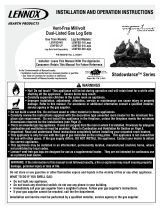
Fig 10 GAS CONTROL
gas control knob to "OFF" and call your service
technician or gas supplier.
9.
Depress the control knob
and turn counterclockwise
to “ON”. Turn flame height knob
counterclockwise to select desired comfort level.
Control
Knob
Push in control knob all the way and
hold in.
NOTE: A periodic visual check of the pilot flames
(Figure 11) and main burner flames (Figure 12) should
be made. The pilot flame should always be present
when the appliance is in operation. See illustrations
below.
If the control knob is not held in
all the way the pilot will not stay lit
when the knob is released.
Do not turn the knob when pushing it in.
Light the pilot (mounted in front of the back burner)
by pushing the spark igniter button several times.
This will cause a spark at the pilot which will ignite
the pilot gas. If the spark does not work, light the
pilot with a match.
* When lighting the pilot it may take several seconds for
gas to reach the pilot.
Continue to hold the control knob in all the way for
Fig 11
NATURAL GAS
ODS PILOT
LIQUID PROPANE
ODS PILOT
about 30 seconds after the pilot is lit.
9.
t. The pilot
Fig 12 MAIN BURNER
Release the knob and it will pop back u
should remain lit. If it goes out, repeat steps 3 through
9.
* If knob does not pop up when released, stop and
immediately call your service technician or gas
supplier.
* If the pilot will not stay lit after several tries, turn
the
11
WARNING:
TAMPERING WITH THE ODS PILOT
WILL VOID THE MANUFACTURER'S WARRANTY.
IMPORTANT:
The gas control has an interlock
device. After shutting off all gas flow, the pilot
burner cannot be relit until the thermocouple has
cooled, allowing the electromagnet to be released
(approx. 60 sec.). The gas control knob is
designed to be operated by hand. DO NOT use any
tools during this operation. Damaged knobs may
result in serious injury.
TO TURN OFF GAS TO APPLIANCE
TEMPORARY SHUTDOWN PROCEDURE:
To turn off main burner only, depress the knob and turn it
clockwise as far as it will go. Do not force.
COMPLETE SHUT-DOWN PROCEDURE:
Turn off all electrical power in firebox. Turn gas control
knob clockwise to the “OFF” position.
OPERATION
Controlling Heat Output Cleaning And Servicing
* The heat output can be controlled by adjusting the
vent free burner control knob.
* Another way to regulate the heat output is to open
the fireplace damper.
If you want:
a. more heat radiated into the room Keep the
damper completely closed
b. less heat radiated into the room open the
fireplace damper to varying degrees.
Important Safeguards
1. To avoid personal injury, do not touch hot
surfaces when the appliance is operating. Touch
only the piezo ignitor and control knob.
Hot Surfaces
a. Grate
b. Burner
c. Logs
d. Surfaces above the opening of the
fireplace
2. Although your gas logs are very realistic in
appearance, it is not a real wood-burning fireplace
and must not be used for burning any material.
* To avoid irreparable damage to the appliance or
personal injury, matches, paper, garbage, or any
other material must not be placed or thrown on top of
the logs or into the flames.
Close supervision is necessary when the appliance is
being operated near children.
Avoid any drafts that alter burner patterns. Do not
allow fans to blow directly into the fireplace. Ceiling
fans may create drafts that alter burner flame
patterns. Sooting and improper burning will occur.
Installation and repair should be done by a qualified
service person. The appliance should be inspected
before use and at least annually by a professional service
person. More frequent cleaning may be required due to
excessive lint from carpeting, bedding, and material, etc.
It is imperative that control components, burners and
circulating air passageways of the appliance be kept
clean.
If the flames show any unusual shapes or
behavior, or the burners fail to ignite
properly, then the burner holes may require
cleaning.
WARNING: TURN OFF VENT FREE BURNER
SYSTEM AND ALLOW TO COOL BEFORE CLEANING
OR SERVICING.
MONTHLY CLEANING
1. If removing logs, when reinstalling, refer to “Log
Assembly Diagram” for correct log placement.
2. Do not use cleaning fluids to clean logs or any part of
the heater.
3. Brush logs with a soft bristle brush or vacuum with
brush attachment.
4. Vacuum loose particles and dust from the front and
rear burner ports, gas control, piezo cover, and grate.
5. Inspect and clean ODS pilot for operation and
accumulation of lint at air intake holes.
6. Verify flame pattern and log placement for proper
operation.
7. Verify smooth and responsive ignition of main burner
and rear burner. Refer to page for proper
pictorial sketch of proper operation.
ANNUAL CLEANING AND INSPECTION
1. Dealer or qualified inspector follow the above steps
for proper servicing and inspection.
12
B
A
C
H
F
G
H
WARNING: Failure to position the parts in accordance with these diagrams or failure to use only parts
specifically approved with this heater may result in property damage or personal injury.
Millivolt Vent Free Burner Assembly
PARTS AND ASSEMBLY IDENTIFICATION MILLIVOLT VALVE
13
J
K
L
WARNING: TURN OFF AND LET COOL BEFORE SERVICING. ONLY A QUALIFIED SERVICE
PERSON SHOULD SERVICE AND REPAIR.
TROUBLE-SHOOTING
Hargrove Manufacturing test fires all Vent Free burner systems before shipment. Each test consists of
lighting the pilot, checking for proper ignition, and leak testing at each connection. Even though all of
these precautions are taken sometimes problems do arise. The following Trouble-Shooting chart lists
several problems with their probable cause and remedy.
OBSERVE PROBLEM
A. When ignitor button is
pressed there is no spark at the
ODS.
B. ODS pilot lights, but flame
goes out when control knob is
released.
C. Appliance shuts off in use.
POSSIBLE CAUSE
1. Ignitor electrode positioned
wrong.
2. Ignitor electrode is broken.
3. Ignitor electrode is not
connected.
4. Ignitor cable is pinched.
5. Ignitor cable is wet.
6. Broken ignitor cable.
7. Bad piezo ignitor.
1. Control knob not fully
depressed.
2. Control knob not pressed in
long enough.
3. Manual shutoff valve not fully
open.
4. Thermocouple connection loose
at valve.
5. Pilot flame not touching
thermocouple, which allows
thermocouple to cool, causing pilot
flame to go out. This problem
could be caused by one or both of
the following:
A) Log gas pressure.
B) Dirty or partially clogged ODS
pilot.
6. Thermocouple damage.
7. Control valve damage.
1. Not enough fresh air available
for ODS pilot to operate.
2. Low gas pressure.
3. ODS pilot is partially clogged.
4. Unstable pilot flame due to
drafts from ceiling fan, hot furnace
register, open door etc…
5. If using damper, unstable pilot
flame from downdrafts.
REMEDY
1. Replace ignitor.
2. Replace ignitor.
3. Reconnect ignitor cable.
4. Free ignitor cable if pinched
by any metal or tubing.
5. Dry ignitor cable.
6. Replace ignitor cable.
7. Replace Piezo ignitor.
1. Press in control knob fully.
2. After ODS pilot lights, keep
control knob pressed in 30
seconds.
3. Fully open manual shutoff
valve.
4. Hand tighten ¼ turn more.
5. Contact local gas company.
6. Replace ODS pilot.
7. Replace control valve.
1. Open door to adjoining
room for added ventilation or
open window.
2. Contact local gas company.
3. Clean ODS pilot.
4. Locate and eliminate drafts.
5. Close damper.
14
OBSERVE PROBLEM
D. When ignitor button is
pressed there is spark at ODS
pilot, but not ignition.
E. Gas odor even when control
knob is in the OFF position.
F. Slight odor during initial
operation.
G. Main burner does not light
after ODS pilot is lit.
H. Delayed ignition of main
burner.
I. Main burner backfiring during
combustion.
J. Appliance produces
unwanted odors.
K. Soot is depositing on logs, in
fireplace, or in room.
TROUBLE-SHOOTING
POSSIBLE CAUSE
1. Gas supply turned off or manual
shutoff valve closed.
2. Control knob not in PILOT
position.
3. Control knob not pressed in
while in PILOT position.
4. Air in gas line.
5. ODS pilot is clogged.
1. Gas leak.
2. Control valve defective.
1. Smell coming from the paint
curing on the logs and burner
system.
1. Burner orifice is clogged.
2. Inlet gas pressure is too low.
3. Gas line obstruction. (pipe
dope, Teflon tape, etc…)
1. Burner orifice is clogged.
2. Inlet gas pressure is too low.
3. Gas line obstruction. (pipe
dope, Teflon tape, etc…)
1. Burner orifice is clogged or
damaged.
2. Inlet gas pressure is too low.
3. Gas line obstruction. (pipe
dope, Teflon tape, etc…)
1. Fresh paint fumes, cleaning
agents, pet hair, or other particles
are cycling thru the fireplace when
it is operating.
2. Gas leak.
1. Logs are not positioned properly
and are obstructing the flame.
2. Main burner has accumulated
dust or other small particles.
REMEDY
1. Turn on gas supply or open
manual shutoff valve.
2. Turn control knob to PILOT
position then depress knob.
3. Press in control knob while
in PILOT position.
4. Continue holding down
control knob. Repeat igniting
operation until air is removed.
5. Clean ODS pilot.
1. Locate and correct all leaks.
2. Contact dealer to receive
further instructions on
correcting problem.
1. Problem will stop after a few
hours of operation. Run the
heater with the damper open if
you have one or open a
window for the first few hours.
1. Clean burner orifice and
main burner.
2. Contact local gas company.
3. Locate and clear
obstruction.
1. Clean or replace burner
orifice. Clean main burner.
2. Contact local gas company.
3. Locate and clear
obstruction.
1. Clean or replace burner
orifice. Clean main burner.
2. Contact local gas company.
3. Locate and clear
obstruction.
1. Ventilate room. Stop using
odor causing products while
heater is running.
2. Locate and correct all leaks.
1. Logs must be repositioned
so they do not come in contact
with the flame.
2. Clean main burner.
15
LIMITED WARRANTY
Logs
Hargrove gas logs carry a limited lifetime warranty against any manufactured defect or breakage. A replacement will be available from the
dealer at which the appliance was purchased. This warranty does not cover breakage caused by excessive handling once installed and fired.
Burner & Grate
If the burner or grate fails due to deterioration within five (5) years of the verified purchase date, a free replacement will be made
available from the dealer at which the appliance was purchased.
Valves, Remote Controls, & Switching Devices
Hargrove warrants all valves, remote controls and switching devices against manufacturing defects which appear within two (2) years of
the verified purchase date. Warranty does not cover products that have been damaged by misuse from overheating. Before any product is
returned a Return Goods Authorization number (RGA) must be issued by Hargrove’s Customer Service Department. All returns must be
accompanied by an explanation of the problem and all necessary parts.
All Other Parts
If any assembled part should fail to operate or be found defective which appear within two years of the verified purchase date, a replacement
will be available from the dealer at which the appliance was purchased.
Buyer shall notify Hargrove Mfg Corp. of any defect covered by this warranty no later than thirty (30) days after defect is discovered.
Failure to provide notice within thirty (30) days shall void the limited warranty.
WHAT IS NOT COVERED
1.
Removal and reinstallation costs.
2.
Labor costs for replacement or repairs.
3.
Transportation or shipping cost.
4.
The cost of a service call to diagnose trouble.
5.
Painted Surfaces.
6.
Damage or defect caused by improper installation, accident, misuse, abuse, alteration, or authorized service technician.
7.
Replacement of burner or combustion chamber resulting from improper storage of the appliance.
LIMITATIONS AND EXCLUSIONS
1.
No one has authority to add to or vary this limited warranty, or to create for Hargrove Manufacturing Corporation any other obligation
or liability in connection with this appliance.
2.
Any implied warranty applicable to this appliance is limited in duration to the same period of time as this written
Warranty. Some states do not allow limitations on how long an implied warranty lasts, so the above limitations may not apply to you.
3.
HARGROVE MANUFACTURING CORPORATION WILL NOT BE LIABLE FOR INCIDENTAL, CONSEQUENTIAL, SPECIAL
OR CONTINGENT DAMAGES YOU MIGHT SUFFER AS A RESULT OF A CLAIM UNDER THIS WRITTEN WARRANTY OR
ANY IMPLIED WARRANTY. Some states do not allow the exclusion or limitation of incidental or consequential damages, so the above
limitations or exclusion may not apply to you.
4.
This warranty applies only to the original purchaser and may not be transferred or assigned.
5.
If you cannot verity the purchase date of the appliance, the warranty period will begin on the date of which the appliance was
manufactured.
6.
Replacement or repair parts are warranted for the remaining period of the original part warranty. Warranty parts must be obtained through
authorized dealers of this product who will provide original factory replacement parts. Failure to use original factory replacement parts
voids this warranty.
7.
The maximum liability of Hargrove Mfg Corp. in connection with this limited warranty shall not in any case exceed the contract price
paid for the product claimed to be defective or unsuitable.
8.
Purchaser or user agrees to hold Hargrove Mfg Corp. harmless from any and all claims by the buyer as a result of injury or damage to an
ultimate user or other person caused by the product sold herein by the seller to the buyer, whether the injury or damage results from the
assembly, installation, operation, shipment, storage, or manufacture of this product. Hargrove Mfg Corp. makes no warranties, expressed
or implied, other than those expressly stated herein. YOUR DUTIES
This appliance must be installed by a qualified installer, operated and maintained in accordance with all applicable codes and the instructions
furnished with the appliance. You must provide a receipt verifying the purchase date of the appliance when making a warranty claim with
the dealer from which the appliance was purchased.
This warranty gives you specific legal rights, and you may also have other rights, which vary from state to state.
CONTACT INFO: Hargrove Manufacturing Corp.
Tele: (800) 725-4166
16
  • Page 1 1
  • Page 2 2
  • Page 3 3
  • Page 4 4
  • Page 5 5
  • Page 6 6
  • Page 7 7
  • Page 8 8
  • Page 9 9
  • Page 10 10
  • Page 11 11
  • Page 12 12
  • Page 13 13
  • Page 14 14
  • Page 15 15
  • Page 16 16

Hargrove HGRGCI User guide

Category
Fireplaces
Type
User guide

The Hargrove HGRGCI vent-free gas log set offers a cozy and efficient heating solution for your home. Designed for use in masonry or factory-built fireplaces, this set operates as an unvented room heater, providing supplemental warmth without the need for a chimney. Its realistic log design and dancing flames create a captivating ambiance, enhancing the aesthetics of your living space. Installation must be performed by qualified professionals to ensure safety and proper operation. Enjoy the convenience and warmth of the Hargrove HGRGCI gas log set in your fireplace.

Ask a question and I''ll find the answer in the document

Finding information in a document is now easier with AI