Page is loading ...

Questions, problems or missing parts? Before returning this item to your retailer, call our customer service department
at 1-877-706-3267, Monday - Thursday, 8am - 6pm, Friday, 8am - 5pm EST.
MODEL #50850, 50851, 50852, 50853
52-INCH HUGGER FAN

2
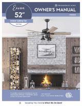
PACKAGE CONTENTS HARDWARE CONTENTS
(not drawn to scale)
Note: Some extra fasteners are included for your
convenience.
Blade Balancing Kit
Plug Button
Blade Washer (x 15)
Blade Screw (x 15)
Wire Connector (x 3)
Pull Chain Extension (x 2)
Mounting Bracket
Blade Arm (x 5)
Blade (x 5)
Lower Bracket
Bulb
Motor
Motor Housing
Switch Housing
Switch
Housing
Cap
Light Kit
Glass Bowl

3
TABLE OF CONTENTS
PREPARATION
Before beginning the assembly of this product, ensure all parts are present. Compare all parts with the package contents list and hardware contents
list. If any part is missing or damaged, do not attempt to assemble the product.
Estimated Assembly Time: 120 minutes
Tools required for assembly (not included): Electrical tape, Phillips Screwdriver, Pliers, Safety Glasses, Step Ladder, and Wire Strippers
Helpful Tools (not included): AC Tester Light, Tape Measure, Wiring Handbook and Wire Cutters
Package Contents .....................................................................................................2
Preparation ..........................................................................................................3
Assembly Instructions ..................................................................................................5
Installation Without Light Kit .............................................................................................9
Operating Instructions .................................................................................................10
Safety Information ....................................................................................................11
Care and Maintenance ................................................................................................11
Troubleshooting ......................................................................................................12
Warranty ...........................................................................................................13
Replacement Parts List ................................................................................................14

4
PREPARATION
1. Turn o power.
Turn o the power to the fan at the breaker
box and the wall switch.
2. Choose mounting option.
Standard Mounting installation is not
available for this item.
Angle Mounting installation is not available
for this item.
Flushmount installation is best suited for
ceilings 8 ft. or lower.
Closemount installation is not available for
this item.
3. Choose suitable location.
Ensure the blades will be at least 30 inches
from any obstructions. Also check the
downrod length to ensure the blades will be
at least 7 feet above the oor.
Failure to disconnect the power supply
prior to installation may result in serious
injury or death.
See page 11 for complete description of
cautions and warnings.
Downrod Mounting
Flushmount Closemount
Angle Mounting

5
ASSEMBLY INSTRUCTIONS
Lower
Bracket
Bracket
Screw
Mounting
Bracket
Hook
Slots
Lower
Bracket
Mounting
Bracket
Bracket
Screws
2. Attach the lower bracket.
Note: Remove the wire restraint from the
wires on top of the lower bracket.
Remove the pre-assembled bracket screws
from the lower bracket. Insert the hook from
one side of the lower bracket into the slot of
the mounting bracket. Then insert the other
side of the lower bracket into the second
slot in the mounting bracket until the four
mounting screw holes are aligned.
1. Install the mounting bracket.
Secure the mounting bracket to the outlet
box (not included) using the washers and
mounting screws supplied with outlet box.
Warning: To reduce the risk of re, electrical
shock, or personal injury, mount the fan to
the outlet box marked “Acceptable for fan
support”.
3. Secure the lower bracket.
Secure the lower bracket to the mounting
bracket with the four previously removed
bracket screws.
x 4x 4
Mounting
Bracket
Outlet Box

6
Black (live)
White (neutral)
Bare/Green (ground)
Black
Blue
White
Green
4. Wire the fan.
Connect household supply and fan wires
according to the diagram and these steps:
• Connect the Green wire from the lower
mounting bracket to the Bare/Green supply
wire.
• Connect the White wire from the fan to the
White supply wire.
• Connect the Black and Blue wires from the
fan to the Black supply wire.
• Secure all wiring connections with wire
connectors.
5. Attach the motor housing to the
mounting bracket.
Partially loosen the two mounting screws
preinstalled in the J-slots and completely
remove the other two mounting bracket
screws from round holes. Lift the motor
housing over the motor aligning the J-slots
in the motor housing with the loosened
mounting bracket screws in the mounting
bracket. Twist the motor housing clockwise
to lock. Then re-insert the two previously
removed mounting bracket screws and
tighten all four screws with a Phillips
screwdriver.
x 3 x 4
Mounting
Bracket
Screw
Note: If there is a second hot supply wire
coming from the outlet box, connect it to the
blue (light power) fan wire for separate light
and fan control.
ASSEMBLY INSTRUCTIONS
6. Attach the blades to blade arms.
Partially insert blade screws along with
blade washers through blade and into blade
arm. Tighten each blade screw, starting with
the one in the middle. Repeat this step for
the remaining blades and blade arms.
x 15
Blade Washer
Blade Arm
Blade Screw

7
7. Attach blade arms to motor.
Remove the ten motor screws from the
underside of the motor. Then, install the
blade arm to the underside of the motor
assembly with the ten previously removed
motor screws.
To install the fan without the light kit,
skip to page 9.
x 10
Blade Arm
Motor Screw
ASSEMBLY INSTRUCTIONS
8. Connect light kit wiring.
Remove the three switch housing screws
from the top of the light kit. Then connect
the single-pin connector from the switch
housing to the single-pin connector from the
light kit -- white to white and blue to black.
Switch
Housing
Screw
Single-pin
Connector
Light Kit
9. Attach light kit to switch
housing.
Secure the light kit to the switch housing
using the previously removed switch
housing screws.
Light Kit
Switch
Housing
Screw
x 3

8
10. Install the two E26-base LED
bulbs.
Important: When replacing bulbs, allow
bulbs and light kit to cool before touching.
Bulb
ASSEMBLY INSTRUCTIONS
11. Install glass bowl.
Attach the glass bowl by inserting the three
spring clips inside the neck of the glass bowl
and rmly push the glass bowl up until it
is secured to the light kit. Note: The glass
bowl will snap into place once installed
properly.
Glass Bowl
Light Kit Spring Clip
12. Attach pull chain extensions.
Feed the pull chains down through the chain
guides in the light kit and attach the pull
chain extensions.
Assembly is complete. Turn on power to
fan at breaker box and the wall switch.
Pull Chain Extension
Chain
Guide

9
1. Install switch housing cap to
switch housing.
Remove the three switch housing screws
from the top of the light kit. Attach the switch
housing cap to the switch housing using the
three switch housing screws. Then, install
the plug button into the center hole of the
switch housing cap.
2. Attach pull chain extension.
When facing the reverse switch, the light
pull chain will be on the left and the fan pull
chain will be on the right.
Note: When installing without a light kit, the
pull chain for the light will not be installed.
INSTALLATION WITHOUT LIGHT KIT (optional)
Switch Housing Cap
Switch Housing
Switch
Housing
Screw
Pull Chain Extension
x 3

10
1. Pull chain operation.
When facing the reverse switch, the light
pull chain will be on the left and the fan pull
chain will be on the right. When installing
without a light kit, the pull chain for the light
will not be installed.
2. Reverse switch operation.
Use the fan reverse switch, located on the
switch housing to optimize your fan for
seasonal performance.
Using a ceiling fan will allow you to raise
your thermostat setting in summer and lower
your thermostat setting in winter without
feeling a dierence in your comfort.
Note: Wait for the fan to stop before moving
the reverse switch.
In warmer weather, push the reverse
switch down which will result in downward
airow creating a wind chill eect.
In cooler weather, push the reverse switch
up which will result in upward airow that
can help move stagnant, hot air o the
ceiling area.
OPERATING INSTRUCTIONS
Fan Pull
Chain
Light Pull
Chain
Reverse
Switch
Reverse Switch

11
SAFETY INFORMATION
CARE AND MAINTENANCE
Please read and understand this entire manual before attempting to assemble, operate or install the product.
• Before you begin installing the fan, disconnect the power by removing fuses or turning o the circuit breakers.
• Make sure all electrical connections comply with local codes, ordinances, the National Electrical Code and ANSI/NFPA 70-199. Hire a qualied electrician or consult a
do-it-yourself wiring handbook if you are unfamiliar with installing electrical wiring.
• Make sure the installation site you choose allows a minimum clearance of 7 ft. from the blades to the oor and at least 30 in. from the end of the blades to any
obstruction.
• The net weight of this fan is: 15.20 lbs.
DANGER: When using an existing outlet box, make sure the outlet box is securely attached to the building structure and can support the full weight of the fan.
Failure to do this can result in serious injury or death. The stability of the outlet box is essential in minimizing wobble and noise in the fan after installation is complete.
WARNING: To avoid personal injury, the use of gloves may be necessary while handling fan parts with sharp edges.
WARNING: Using a full-range dimmer switch to control fan speed will cause a loud humming noise from the fan. To reduce the risk of re or electric shock, do NOT
use a full-range dimmer switch to control the fan speed.
WARNING: To reduce the risk of re, electric shock or personal injury, mount the fan to an outlet box marked “ACCEPTABLE FOR FAN SUPPORT” and use the
mounting screws provided with the outlet box. Most outlet boxes commonly used for the support of lighting xtures are not acceptable for fan support and may need to
be replaced. Consult a qualied electrician if in doubt. Secure the outlet box directly to the building structure. The outlet box and its support must be able to support the
moving weight of the fan (at least 35 lbs.).
WARNING: To reduce the risk of re, electric shock or personal injury, wire connectors provided with this fan are designed to accept only one 12-gauge house wire
and two lead wires from the fan. If your house wire is larger than 12-gauge and/or there is more than one house wire to connect to the two fan lead wires, consult an
electrician for the proper size wire connectors to use.
WARNING: To reduce the risk of re, electric shock or personal injury, do not bend the blade arms when installing them, balancing the blades or cleaning the fan.
Do not insert objects between the rotating fan blades.
WARNING: To reduce the risk of personal injury, use only parts provided with this fan. The use of parts OTHER than those provided with this fan will void the warranty.
CAUTION: Be sure the outlet box is properly grounded or a ground (green or bare) wire is present.
CAUTION: Carefully check all screws, bolts, and nuts on the fan assembly ensure they are secured.
At least twice each year, lower the canopy to check the downrod assembly and tighten all screws on the fan. Clean the motor housing with only a soft brush or lint-free cloth
to avoid scratching the nish. Clean the blades with a lint-free cloth.
Important: Shut o the main power supply before you begin any maintenance task. Do NOT use water or a damp cloth to clean the fan.

12
TROUBLESHOOTING
The fan does not move.
The fan is noisy.
The fan wobbles
excessively.
The fan operates correctly
but the lights are not
working.
1. Firmly push the reverse switch completely up or down.
2. Make sure the wall switch is turned on.
3. Ensure power is on at wall switch and breaker box
4. Turn the power o and check all wire connections at the ceiling outlet box.
1. Check and tighten all screws that hold the fan blades to the blade arms and motor.
2. Replace any blade that is cracked or damaged.
3. Do not use a variable-speed wall control to control the fan speed.
4. Ensure the outlet box is securely mounted to the building structure.
5. Ensure the mounting bracket is securely mounted to the outlet box.
1. Tighten all screws that hold the fan blades to the blade arms and blade arms to motor.
2. Switch one blade with a blade from the opposite side. Or balance the fan using the blade balancing kit.
3. Turn o power. Loosen the canopy and verify that the mounting bracket is secure to the electrical outlet box. The
mounting bracket must be ush without movement against the outlet box.
4. Use a longer downrod or move the fan to another location if the fan is too close to the ceiling.
5. Ensure the mounting bracket is securely mounted to the outlet box.
6. Tighten the set screws in the yoke.
1. Install new bulbs.
2. Ensure the single-pin connectors from the switch housing to the light kit are connected properly.
3. Turn the power o and check all wire connections between the fan and outlet box.
PROBLEM CORRECTIVE ACTION

13
LIFETIME LIMITED WARRANTY
The manufacturer warrants this fan to be free from defects in workmanship and materials present at time of shipment from the factory for a lifetime
from the date of purchase by the original purchaser. The retailer also warrants that all other fan parts, excluding any glass or acrylic blades, to be
free from defects in workmanship and material at the time of shipment from the factory for a period of one year after the date of purchase by the
original purchaser. The manufacturer agrees to correct such defects without charge or at its option replace the ceiling fan with a comparable or
superior model.
To obtain warranty service, present a copy of the receipt as proof of purchase. All costs of removing and reinstalling the product are your
responsibility. Any damage to any part such as by accident or misuse or improper installation or by axing any accessories, is not covered by this
warranty. The manufacturer assumes no responsibility whatsoever for fan installation during the limited lifetime warranty. Any service performed by
an unauthorized person will render the warranty invalid.
Due to varying climate conditions, this warranty does not cover any changes in brass nish, including rusting, pitting, corroding, tarnishing or peeling.
Brass nishes of this type give their longest useful life when protected from varying weather conditions. Any glass provided with this fan is not
covered by the warranty.
Any replacement of defective parts from the ceiling fan must be reported within the rst year from the date of purchase. For the balance of the
warranty, call our customer service department for return authorization and shipping instructions so that we may repair or replace the ceiling fan.
Any fan or parts returned improperly is the sole responsibility of the purchaser. There is no other expressed warranty. The manufacturer disclaims
any and all warranties. The duration of any implied warranty which cannot be disclaimed is limited to the time period as specied in the expressed
warranty. The manufacturer shall not be liable for incidental, consequential, or special damages arising out of or in connection with product use or
performance except as may otherwise be accorded by law. This warranty gives specic legal rights, and you may also have other rights which vary
from state to state.
This warranty supersedes all prior warranties.
Note: A small amount of “wobble” is normal and should not be considered a defect.

14
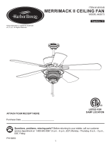
REPLACEMENT PARTS LIST
9352 • 102518
For replacement parts, call our customer service department at 1-877-706-3267, Monday - Thursday, 8am - 6pm, Friday 8am - 5 pm, EST.
A
E
B
F
G
C
D
HW
50850 50851 50852 50853
A Motor Housing 4L000007740 4L000007750 4A000009480 4A000009490
B Mounting Bracket 4L000007760 4L000007770 4L000009280 4L000007770
C Light Kit 4A000009390 4A000009410 4A000009420 4A000009430
D Glass Bowl 4A160620001 4A160620001 4A160620001 4A160620001
E Switch Housing Cap 4A000005080 4A000005090 4A000009510 4A000009520
F Blade Arm 4A071890006 4A071890007 4A071890012 4A071890013
G Blade 4A084360001 4A084360002 4A084360003 4A084360004
HW Hardware Bag 4A000009460 4A000009470 4A000009440 4A000009450
/