United Kingdom
en
Installation, User and Service Manual
Control panel
Gas 210 ECO PRO
210-80 – 210-120 – 210-160 – 210-200

Dear Customer,
Thank you very much for buying this appliance.
Please read through the manual carefully before using the product, and keep it in a safe place for later reference. In order to
ensure continued safe and efficient operation we recommend that the product is serviced regularly. Our service and customer
service organisation can assist with this.
We hope you enjoy years of problem-free operation with the product.

Contents
1 Safety . . . . . . . . . . . . . . . . . . . . . . . . . . . . . . . . . . . . . . . . . . . . . . . . . . . . . . . . . . . . . . . . . . . . . . . . . . . . . . . . . . . . . . . . . . . . 4
1.1 General safety instructions . . . . . . . . . . . . . . . . . . . . . . . . . . . . . . . . . . . . . . . . . . . . . . . . . . . . . . . . . . . . . . . . . . . . . . . 4
1.2 Recommendations . . . . . . . . . . . . . . . . . . . . . . . . . . . . . . . . . . . . . . . . . . . . . . . . . . . . . . . . . . . . . . . . . . . . . . . . . . . . . 4
1.3 Liabilities . . . . . . . . . . . . . . . . . . . . . . . . . . . . . . . . . . . . . . . . . . . . . . . . . . . . . . . . . . . . . . . . . . . . . . . . . . . . . . . . . . . . . 4
1.3.1 Manufacturer's liability . . . . . . . . . . . . . . . . . . . . . . . . . . . . . . . . . . . . . . . . . . . . . . . . . . . . . . . . . . . . . . . . . . . 4
1.3.2 Installer's liability . . . . . . . . . . . . . . . . . . . . . . . . . . . . . . . . . . . . . . . . . . . . . . . . . . . . . . . . . . . . . . . . . . . . . . . 5
1.3.3 User's liability . . . . . . . . . . . . . . . . . . . . . . . . . . . . . . . . . . . . . . . . . . . . . . . . . . . . . . . . . . . . . . . . . . . . . . . . . .5
2 About this manual . . . . . . . . . . . . . . . . . . . . . . . . . . . . . . . . . . . . . . . . . . . . . . . . . . . . . . . . . . . . . . . . . . . . . . . . . . . . . . . . . . . 6
2.1 Additional documentation . . . . . . . . . . . . . . . . . . . . . . . . . . . . . . . . . . . . . . . . . . . . . . . . . . . . . . . . . . . . . . . . . . . . . . . . 6
2.2 Symbols used . . . . . . . . . . . . . . . . . . . . . . . . . . . . . . . . . . . . . . . . . . . . . . . . . . . . . . . . . . . . . . . . . . . . . . . . . . . . . . . . . 6
2.2.1 Symbols used in the manual . . . . . . . . . . . . . . . . . . . . . . . . . . . . . . . . . . . . . . . . . . . . . . . . . . . . . . . . . . . . . . 6
3 Control panel description . . . . . . . . . . . . . . . . . . . . . . . . . . . . . . . . . . . . . . . . . . . . . . . . . . . . . . . . . . . . . . . . . . . . . . . . . . . . . .7
3.1 General description . . . . . . . . . . . . . . . . . . . . . . . . . . . . . . . . . . . . . . . . . . . . . . . . . . . . . . . . . . . . . . . . . . . . . . . . . . . . .7
3.2 What each key means . . . . . . . . . . . . . . . . . . . . . . . . . . . . . . . . . . . . . . . . . . . . . . . . . . . . . . . . . . . . . . . . . . . . . . . . . . .7
3.3 Meaning of the symbols on the display . . . . . . . . . . . . . . . . . . . . . . . . . . . . . . . . . . . . . . . . . . . . . . . . . . . . . . . . . . . . . .7
4 Commissioning . . . . . . . . . . . . . . . . . . . . . . . . . . . . . . . . . . . . . . . . . . . . . . . . . . . . . . . . . . . . . . . . . . . . . . . . . . . . . . . . . . . . . 8
4.1 Start-up program . . . . . . . . . . . . . . . . . . . . . . . . . . . . . . . . . . . . . . . . . . . . . . . . . . . . . . . . . . . . . . . . . . . . . . . . . . . . . . .8
5 Operation . . . . . . . . . . . . . . . . . . . . . . . . . . . . . . . . . . . . . . . . . . . . . . . . . . . . . . . . . . . . . . . . . . . . . . . . . . . . . . . . . . . . . . . . . .9
5.1 Use of the control panel . . . . . . . . . . . . . . . . . . . . . . . . . . . . . . . . . . . . . . . . . . . . . . . . . . . . . . . . . . . . . . . . . . . . . . . . . 9
5.1.1 Browsing in the menus . . . . . . . . . . . . . . . . . . . . . . . . . . . . . . . . . . . . . . . . . . . . . . . . . . . . . . . . . . . . . . . . . . 9
6 Settings . . . . . . . . . . . . . . . . . . . . . . . . . . . . . . . . . . . . . . . . . . . . . . . . . . . . . . . . . . . . . . . . . . . . . . . . . . . . . . . . . . . . . . . . . . 10
6.1 Changing the parameters . . . . . . . . . . . . . . . . . . . . . . . . . . . . . . . . . . . . . . . . . . . . . . . . . . . . . . . . . . . . . . . . . . . . . . . 10
6.2 Changing the user-level parameters . . . . . . . . . . . . . . . . . . . . . . . . . . . . . . . . . . . . . . . . . . . . . . . . . . . . . . . . . . . . . . .10
6.3 Setting the parameters in the Installer level . . . . . . . . . . . . . . . . . . . . . . . . . . . . . . . . . . . . . . . . . . . . . . . . . . . . . . . . . 11
6.3.1 Setting full load . . . . . . . . . . . . . . . . . . . . . . . . . . . . . . . . . . . . . . . . . . . . . . . . . . . . . . . . . . . . . . . . . . . . . . . 11
6.3.2 Setting low load . . . . . . . . . . . . . . . . . . . . . . . . . . . . . . . . . . . . . . . . . . . . . . . . . . . . . . . . . . . . . . . . . . . . . . . 11
6.3.3 Restoring to factory settings . . . . . . . . . . . . . . . . . . . . . . . . . . . . . . . . . . . . . . . . . . . . . . . . . . . . . . . . . . . . . 12
6.3.4 Activating the manual mode menu . . . . . . . . . . . . . . . . . . . . . . . . . . . . . . . . . . . . . . . . . . . . . . . . . . . . . . . . 12
6.4 Reading the various current values . . . . . . . . . . . . . . . . . . . . . . . . . . . . . . . . . . . . . . . . . . . . . . . . . . . . . . . . . . . . . . . 13
7 Troubleshooting . . . . . . . . . . . . . . . . . . . . . . . . . . . . . . . . . . . . . . . . . . . . . . . . . . . . . . . . . . . . . . . . . . . . . . . . . . . . . . . . . . . .14
7.1 Error codes . . . . . . . . . . . . . . . . . . . . . . . . . . . . . . . . . . . . . . . . . . . . . . . . . . . . . . . . . . . . . . . . . . . . . . . . . . . . . . . . . . 14
7.1.1 Blocking . . . . . . . . . . . . . . . . . . . . . . . . . . . . . . . . . . . . . . . . . . . . . . . . . . . . . . . . . . . . . . . . . . . . . . . . . . . . . 14
7.1.2 Lock-out . . . . . . . . . . . . . . . . . . . . . . . . . . . . . . . . . . . . . . . . . . . . . . . . . . . . . . . . . . . . . . . . . . . . . . . . . . . . .14
7.2 Blockage and fault memory . . . . . . . . . . . . . . . . . . . . . . . . . . . . . . . . . . . . . . . . . . . . . . . . . . . . . . . . . . . . . . . . . . . . . .15
7.2.1 Reading out the error memory . . . . . . . . . . . . . . . . . . . . . . . . . . . . . . . . . . . . . . . . . . . . . . . . . . . . . . . . . . . .15
7.2.2 Clearing error memory . . . . . . . . . . . . . . . . . . . . . . . . . . . . . . . . . . . . . . . . . . . . . . . . . . . . . . . . . . . . . . . . . .16
Contents
7698035 - v.01 - 19022018 3

1 Safety
1.1 General safety instructions
Adhere strictly to the specific safety instructions in this
manual.
Danger of electric shock
This equipment operates using electricity.
Disconnect the equipment from the power sup
ply before making electrical connections.
Only qualified professionals are authorised to
work on the appliance and the installation.
Only the manufacturer is authorised to carry out
repairs.
Warning
If the mains lead is damaged, it must be replaced
by the original manufacturer, the manufacturer's
dealer or another suitably skilled person to pre
vent hazardous situations from arising.
1.2
Recommendations
Only qualified professionals are authorised to work on
the control panel and the installation.
Important
Store this document in the document wallet on
the inside of the boiler casing.
Keep the control panel accessible at all times.
1.3
Liabilities
1.3.1 Manufacturer's liability
Our products are manufactured in compliance with the
requirements of the various Directives applicable. They
are therefore delivered with the
marking and any
documents necessary. In the interests of the quality of
our products, we strive constantly to improve them. We
therefore reserve the right to modify the specifications
given in this document.
Our liability as manufacturer may not be invoked in the
following cases:
Failure to abide by the instructions on installing the
appliance.
1 Safety
4 7698035 - v.01 - 19022018

Failure to abide by the instructions on using the appli
ance.
Faulty or insufficient maintenance of the appliance.
1.3.2 Installer's liability
The installer is responsible for the installation and initial
commissioning of the appliance. The installer must ob
serve the following instructions:
Read and follow the instructions given in the manuals
provided with the appliance.
Install the appliance in compliance with prevailing leg
islation and standards.
Carry out initial commissioning and any checks neces
sary.
Explain the installation to the user.
If maintenance is necessary, warn the user of the obli
gation to check the appliance and keep it in good
working order.
Give all the instruction manuals to the user.
1.3.3
User's liability
To guarantee optimum operation of the system, you
must abide by the following instructions:
Read and follow the instructions given in the manuals
provided with the appliance.
Call on a qualified professional to carry out installation
and initial commissioning.
Get your installer to explain your installation to you.
Have the required inspections and maintenance car
ried out by a qualified installer.
Keep the instruction manuals in good condition close
to the appliance.
1 Safety
7698035 - v.01 - 19022018 5

2 About this manual
2.1 Additional documentation
This manual forms part of the documents pack supplied with the boiler.
2.2
Symbols used
2.2.1 Symbols used in the manual
This manual uses various danger levels to draw attention to special in
structions. We do this to improve user safety, to prevent problems and to
guarantee correct operation of the appliance.
Danger
Risk of dangerous situations that may result in serious personal
injury.
Danger of electric shock
Risk of electric shock.
Warning
Risk of dangerous situations that may result in minor personal in
jury.
Caution
Risk of material damage.
Important
Please note: important information.
See
Reference to other manuals or pages in this manual.
2 About this manual
6 7698035 - v.01 - 19022018

3 Control panel description
3.1 General description
The HMI Gas 210 ECO PRO control panel is designed for the operation
and control of the Gas 210 ECO PRO boilers.
The control panel can be used to:
Read out the values measured in the heating circuit.
Read out error codes.
Read out and set boiler parameters.
Set a chimney sweep mode.
Important
For operation of the Gas 210 ECO PRO boiler: each module has
its own control panel.
3.2
What each key means
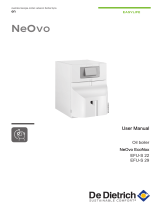
1
Display
2
[Menu] key
3
[Chimney sweep] key
4
[Escape] or [Reset] key
5
[Central heating temperature] or [-] key
6
[DHW temperature] or [+] key
7
[Enter] key or [Service] indicator
8
On/off switch
The display has several positions and symbols and provides information
about the operating status of the boiler and any faults. A maintenance
message may also appear on the display. Numbers, dots and/or letters
may be shown. The symbols above the function keys indicate the current
function.
3.3
Meaning of the symbols on the display
Tab.1 Symbols on the display
Information menu: read out various current values.
ECO mode is on.
User menu: settings for user level parameters can be changed.
Manual mode menu: manual mode can be configured.
Installer menu: parameters at installer level can be changed.
Error menu: errors can be read out.
Central heating operation is switched off.
DHW operation is switched off.
Chimney sweep mode is enabled (forced full load or part load for O
2
/CO
2
measurement).
Burner output level
Central heating operation is enabled.
DHW operation is enabled.
Fig.1 Control panel
AD-4000041-01
Bar
2
3
5
1
8
6 7
4
3 Control panel description
7698035 - v.01 - 19022018 7

4 Commissioning
4.1 Start-up program
Immediately after the power is connected, the start-up program will begin.
Various short items of information appear on the screen during start-up.
The following messages are displayed one after the other:
Display of the control panel version ( ).
Display of the CU board software version ( ).
Display of the CU board parameter version ( ).
When the letters are flashing on the display, then the phase and
neutral have been connected incorrectly. Swap the wires of the power
supply cable on the connection box.
Once the start-up program has run, the main display appears.
Important
If no key is pressed for 3 minutes, the standby screen appears
with the and symbols.
Important
If a fault occurs during start-up, the symbol appears with a
flashing error code on the display. The meaning of the error codes
can be found in the error table.
4 Commissioning
8 7698035 - v.01 - 19022018

5 Operation
5.1 Use of the control panel
The meaning of the symbols in this display are described elsewhere in this
user manual.
If no key is pressed for 3 minutes, the display lighting switches off and the
display only shows the and symbols. Press any key to activate the
display: the current boiler status and current operating code will be shown
on the display. If an error has occurred, this is permanently displayed.
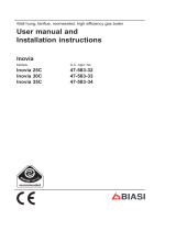
5.1.1
Browsing in the menus
1. Press the key to activate the regulator from the stand-by screen.
The symbol flashes in the menu bar.
2. Press the key to move the cursor to the right.
3. Press the key to move the cursor to the left.
4. Press the key to confirm the selection of the desired menu.
5. Press the or key to change the value.
6. Press the key to confirm the value.
7. Press the key once to go to the previous step, or twice to go
back to the main display.
Fig.2 Browsing in the menus
AD-4000061-01
2x
5 Operation
7698035 - v.01 - 19022018 9

6 Settings
6.1 Changing the parameters
The boiler’s control unit is set for the most common central heating sys
tems. These settings will ensure that virtually every central heating system
operates effectively. The user or the installer can optimise the parameters
as required.
For operation in open vented systems, the parameter must be ad
justed.
Caution
Modification of the factory settings may impair boiler operation.
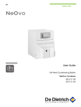
6.2
Changing the user-level parameters
The parameters at user level ( to ) can be changed by the user as
required.
1. Navigate to the user menu.
The symbol flashes in the menu bar.
2. Select the user menu using the key.
: appears with flashing .
3. Press the key.
: appears with flashing .
4. Press the key.
(min.) appears and flashes (factory setting).
5. Change the value by pressing the or key.
6. Confirm the value with the key.
: appears with flashing .
7. Press the key twice to go back to the main display.
Fig.3 Access to the user-level parameters
AD-4000051-01
2x
2x
6 Settings
10 7698035 - v.01 - 19022018

6.3 Setting the parameters in the Installer level
Parameters at installer level (see table of parameters) may be modified
only by a recognised installer. To prevent unwanted modifications to set
tings, some parameters can only be changed after the special access
code is entered.
1. Navigate to the Installer menu.
The symbol flashes in the menu bar.
2. Select the installer menu using the key.
appears on the display.
3.
Using the or keys, set the installer code .
4. To confirm, press the key.
appears.
5. Press the key.
The value °C will appear (factory setting).
6. Change the value by pressing the or keys. Reduce the value
to °C, for example, using the key.
7. Press the key to confirm the value.
appears.
8. Set any other parameters by selecting them using the or keys.
9. Press the key twice to go back to the main display.
Important
The main menu will appear even if no keys are pressed for 3 mi
nutes.
6.3.1 Setting full load
1. Press the key.
The symbol will appear in the display.
2. Wait a while until appears in the display.
Full load has now been set.
6.3.2 Setting low load
1. Press the key.
The symbol will appear in the display.
2. Wait a while until appears in the display.
3. Press the key until appears on the display.
Low load has now been set.
Fig.4 Access to the installer level
AD-4000048-01
4x
2x
Fig.5 Setting full load
AD-4000053-01
1x
Fig.6 Setting low load
AD-4000054-01
1x
6 Settings
7698035 - v.01 - 19022018 11

6.3.3 Restoring to factory settings
1. Navigate to the Installer menu.
The symbol flashes in the menu bar.
2. Select the installer menu using the key.
The text {7}{8}{9}{10}{11}{12} flashes in the display.
3. Using the or keys, set the installer code .
4. To confirm, press the key.
: appears with a flashing .
5. Press the key several times until : appears on the display
with a flashing .
6. To confirm, press the key.
appears with a flashing . This is the current value of X for
dF. Check this against the value of X on the type plate.
7. Enter the value of X shown on the type plate using the or key.
8. To confirm, press the key.
: appears with a flashing . This is the current value of Y
for dU. Check this against the value of Y on the type plate.
9. Enter the value of Y shown on the type plate using the or key.
10. To confirm, press the key.
The factory settings are reset.
11. The display shows the main display.
6.3.4 Activating the manual mode menu
In some cases, it may be necessary to set the boiler to manual mode, for
example when the regulator has not yet been connected.
1. Navigate to the manual mode menu.
The symbol flashes in the menu bar.
2. Press the key to open the menu.
The minimum flow temperature value appears on the screen.
3. Press the or key to temporarily change this value in manual
mode.
4. To confirm, press the key.
The boiler is now set to manual mode.
5. Press the key twice to stop manual mode and to go back to the
main display.
Fig.7 Restoring to factory settings
AD-4000055-01
4x
Fig.8 Activating manual mode
AD-4000050-01
3x
2x
6 Settings
12 7698035 - v.01 - 19022018

6.4 Reading the various current values
The following current values can be read in the information menu :
= Status.
= Sub-status.
= Flow temperature (°C).
= Return temperature (°C).
= Boiler temperature (°C).
= Outside temperature (°C). (If connected).
= Heat exchanger temperature (°C).
= Internal setpoint (°C).
= Ionisation current (μA).
= Fan speed (rpm).
= Water pressure (bar). (If connected).
= Supplied heat output (%).
The current values can be read as follows:
1. Navigate to the information menu
The symbol flashes in the menu bar.
2. Confirm the menu selection with the key.
The screen alternates between the parameter and the current
status, e.g. .
3. Press the key.
The screen alternates between the parameter and the current
sub-status, e.g. .
4. Press the key.
The screen alternates between the parameter and the current
flow temperature, e.g. °C.
5. Press the key several times consecutively to scroll through the
various parameters.
At a certain point, the readout cycle starts again with the pa
rameter.
6. Press the key twice to go back to the main display.
Fig.9 Reading the current values
AD-4000049-01
2x
6 Settings
7698035 - v.01 - 19022018 13

7 Troubleshooting
7.1 Error codes
The boiler is fitted with an electronic regulation and control unit. The heart
of the control is a microprocessor, the
Comfort Master
©
, which both pro
tects and controls the boiler. In the event of an error, a corresponding
code is displayed.
The meaning of the error codes can be found in the error table.
Important
Note the error code displayed. The error code is needed to find
the cause of the error quickly and correctly and for any support
from Remeha.
7.1.1 Blocking
A (temporary) blocking mode is a boiler status, resulting from an abnormal
state. The display shows a blocking code (for example ). The con
trol unit makes a number of attempts to start the boiler again. The blocking
codes can be read out as follows:
1. Press the key, followed by the key.
will now appear flashing in the menu bar. = .
2. Press the key.
and the blocking code will appear.
Important
The boiler automatically returns to operation once the cause of the
blocking has been removed.
The meaning of the blocking codes can be found in the table of blocking
codes.
7.1.2 Lock-out
If the blocking conditions still exist after various start attempts, the boiler
goes into lock-out (also called error). The boiler will also lock out if an error
is signalled anywhere in the boiler. An error code will appear on the dis
play. The error code is displayed as follows:
the symbol
the symbol
the error code, for example
The meaning of the error codes can be found in the error table. Note the
error code.
See
User manual for the boiler.
Important
The error code is needed to find the cause of the error quickly and
correctly and for any support from Remeha.
1. Press the key for two seconds.
If the error code continues to display, search for the cause in the
error table and apply the solution.
Important
If the display shows rather than , switch the boiler off
for 10 seconds and then back on. Try to reset the error code
again.
7 Troubleshooting
14 7698035 - v.01 - 19022018

7.2 Blockage and fault memory
The boiler control unit has an error memory. This stores the 16 most re
cent blockages and the 16 most recent faults.
7.2.1 Reading out the error memory
1. Navigate to the error menu.
The symbol flashes in the menu bar.
2. Press the key to open the menu.
appears in the display ( is the number of displayed
shutdowns)
3. Use the or key to select the list of shutdowns ( ) or errors
( ).
4. Press the key to confirm the selection.
{41}{42} or {43}{44}{45}{46}{47}{48}{49}{50}{51}{52} ap
pears on the display.
5. The error list or blocking list can be displayed by pressing the or
key.
6. Press the key to view details of the blocking.
For example from
7. Press the or keys to view the following data:
= Number of times that the error occurred.
= Number of burning hours.
= Status.
= Sub-status.
= Flow temperature (°C).
= Return temperature (°C).
= Boiler temperature (°C).
= Outside temperature (°C).
= Heat exchanger temperature (°C).
= Internal setpoint (°C).
= Ionisation current (μA).
= Fan speed (rpm).
= Water pressure (bar).
{125} {126}{127}{128} = Supplied heat output (%).
8. Press the key to interrupt the display cycle.
or {137} {138}{139}{140} appears with a flashing =
last error that occurred.
9. Press the or key to view the following errors, if applicable.
10. Press the key twice to go back to the main display.
Fig.10 Reading out the error memory
AD-4000047-01
t/m
5x
2x
7 Troubleshooting
7698035 - v.01 - 19022018 15

7.2.2 Clearing error memory
When reading out the error memory, appears last in the list (or
for shutdowns); in both cases, the letters will flash.
Clear the errors or shutdowns as follows:
1. Press the key.
The display shows a flashing .
2. Press the key to change the setting to .
flashes in the display.
3.
Press the key to confirm the selection.
The list of errors (or shutdowns) is cleared.
4. Press the key twice to go back to the main display.
Fig.11 Clearing error memory
AD-4000052-01
2x
7 Troubleshooting
16 7698035 - v.01 - 19022018

7 Troubleshooting
7698035 - v.01 - 19022018 17

7 Troubleshooting
18 7698035 - v.01 - 19022018

© Copyright
All technical and technological information contained in these technical instructions, as well as any drawings and technical de
scriptions supplied, remain our property and shall not be multiplied without our prior consent in writing. Subject to alterations.

Remeha Commercial UK
Innovations House
3 Oaklands Business Centre
Oaklands Park
RG41 2FD Wokingham
T +44 (0)118 978 3434
F +44 (0)118 978 6977
E boilers@remeha.co.uk
7698035 - v.01 - 19022018
7698035
/