Page is loading ...

OFF.
When the fan is turned ON manually, the
countdown timer will run your fan for your
selected period of time, then turn your fan
4
1
2
3
5
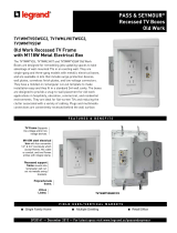
WHITE
BLACK
RED
GROUND
BLUE
120V LINE AC
WALL ENCLOSURE
LIGHT
FIGURE #1
FAN
FIGURE #2
FIGURE #3
HSWC3
Bathroom Condensation Control
with Light Control
ENGLISH
LANGUAGE
MANUAL
DewStop
®
800.233.6251
1.877.BY.LEGRAND
www.legrand.us
www.legrand.ca
341176
(D.) MOUNTING IN WALL ENCLOSURE
1. Attach wires (as shown in FIGURE #1).
(A.) ABOUT DewStop
®
DewStop is intended for condensation problem areas of a
home, such as near the shower or bath. If condensation is
a problem or is suspected to be a problem, simply replace
your existing fan switch with DewStop. For DewStop to
sense condensation, the room will need to show visible
signs of wetness attaching to surfaces, such as steam on
walls / mirrors / fixtures. Visible steam in the air is not the
problem, the problem occurs when moisture in the air
becomes too heavy and the air cannot support the
moisture. The moisture then moves to surfaces (this is the
dew point), triggering the DewStop sensors. The
remarkable DewStop product is constantly checking the air
for condensation. At the right time, DewStop will turn ON
your fan and run the fan to clear the room. NOTE: A good
quality fan properly sized for the room is essential to the
successful removal of moisture from any room. DewStop
only detects condensation, it cannot stop it. DewStop relies
on a closed room and a quality fan to properly detect
condensation and dry a room.
(B.) INSTALLATION INSTRUCTIONS
CAUTION
1. Use only a 120V AC 60Hz power supply
connection.
2. For indoor use only.
3. Do not exceed DewStop’s maximum electrical load
ratings, as indicated on the product label.
4. Must be installed and used in accordance with
your local electrical codes.
5. If a bare copper or green ground connection is
not available in the wall box, contact a
licensed electrician for installation.
2. Tuck wires into wall enclosure and fasten DewStop
to the wall enclosure with the two screws provided
(See FIGURE #2).
3. Attach the wall plate (See FIGURE #3).
(C.) INSTALLATION STEPS
1. WARNING
To avoid fire or risk of electrical shock, turn OFF
power at circuit breaker or disconnect fuse. Test the
power is OFF before you begin wiring.
2. BEFORE YOU MOUNT THE CONTROL
(new installation) Install DewStop in a 3½ inch deep
single-gang or multi-gang electrical wall enclosure.
OR (replacement of existing switch) remove
existing wall plate and switch device being
replaced.
3. ATTACH POWER WIRE, LIGHT WIRE, AND
FAN WIRE
Attach 120V AC 60Hz 3-wire power (Hot / Neutral /
Ground) inside the wall enclosure with a minimum
of 6 inch leads. Attach fan three wire leads inside
the wall enclosure also with minimum 6 inch leads.
If an existing power connection is used in an
existing wall enclosure you must confirm proper AC
120V Hot / Neutral / Ground are available.
4. CONNECT WIRING
General instructions for all configurations:
Make sure the wall enclosure, fan, light, and
DewStop are properly grounded. (See FIGURE #1).
Make sure ground wire is securely fastened. Tighten all
ground screws or wire nuts securely. Use the proper
sized wire nut for #14 or #12 wire. Make sure to strip
back the copper wire 5/8 inch and twist wire and
nut clockwise.
6. For use with permanently installed 120V AC
powered fans only.
7. Use only #14 or #12 copper wire connections.
WARNING
Turn OFF circuit breaker or remove fuse(s) and test
that power is OFF before wiring. Wiring DewStop
live can cause serious risk of electrical shock
and/or damage the control, voiding the warranty.
FOR SAFETY, THIS PRODUCT MUST BE
INSTALLED IN A GROUNDED WALL ENCLOSURE. If
you are unfamiliar with methods of installing
electrical wiring, secure the services of a qualified
licensed electrician. USE ONLY COPPER WIRE, DO
NOT use aluminum wire with this device.
IMPORTANT
Read each step carefully and perform in sequence.
DewStop will not work or will become damaged if
wires are connected incorrectly. To prevent
damage, connect DewStop exactly as shown in the
installation diagrams, otherwise warranty will be
voided. Prior to wiring, straighten or clip ends of
wire such that ends of each wire are straight (if
using DewStop to replace an existing switch). Strip
wire insulation at the end of each wire to expose
5/8 inch (16 mm) of copper. Where instructed to
make a connection, twist ends of stripped wires
together and twist a proper connector clockwise
until secure.
10
7
8
9
11
6
FIGURE #4
BLUE LED LIGHT
FAN ON/OFF
TIMER AND SENSOR SETTINGS
LIGHT ON/OFF
FIGURE #5
INCLUDED TOOL
Use to remove cover and
adjust settings dials.
CONDENSATION SENSOR
FIGURE #6
AROUND EDGES
PUNCH-OUTS
WIRE ACCESS
VENT GROOVES
(Example)
APPLY
CAULKING
in these
types of
areas
WALL
ENCLOSURES
VARY IN
DESIGN;
SEAL ANY
OPENINGS
FOUND
(E.) CONTROL FUNCTIONS
(K.) AIR DRAFTS IN WALL ENCLOSURE
Older homes may experience air flowing (drafts) from
the inside wall cavity into or out of the wall enclosure
depending on the draft situation. If your DewStop is
experiencing problems sensing condensation, sealing
any enclosure openings is needed. The wall enclosure
is easy to seal with standard painter’s caulking and a
caulking gun. To begin you must DISCONNECT all
electrical power to the control before sealing the
openings. Unscrew all box switches and pull them
forward to allow access to the back of the enclosure.
Apply caulking into all openings in the enclosure, even
the very small ones. Seal every opening and around
electrical wires at their entering point. Also seal the
perimeter around the enclosure between the wall board
and the enclosure. This will stop heat loss and allow
DewStop to sense the room and not the drafts in the
walls. See FIGURE #6:
Blue LED Light: Lets you know when your fan is on
(especially useful for fans with low sound levels).
Condensation Sensor: Senses moisture in the room
and turns your fan ON and OFF automatically.
Light ON/OFF: Turns light ON and OFF.
Timer and Sensor Settings: Countdown timer (left)
and moisture sensitivity
(right) settings (hidden
behind a removable cover ‒
see pages 7-8 for details)
Fan ON/OFF: Turns countdown timer ON and OFF
(can be used to temporarily override
condensation sensor).
(G.) MANUAL ON/OFF
Press the “Fan ON/OFF” button once to manually turn
fan ON, and again to turn fan OFF.
(F.) CHANGING THE SETTINGS
By default, DewStop comes with the moisture
sensitivity set to average levels, and the countdown
timer set to 30 minutes. To change the settings, remove
the "Timer and Sensor Settings" cover by taking off the
face plate and then inserting the end of the included
tool (or a non-metal tool of your own) into the two
holes on either side of the control (see FIGURE #5).
Use the included tool to turn the settings dials. The
countdown timer can be set between 5‒60 minutes.
Moisture sensitivity can be set at low, average, or high
sensitivity. Once you change a setting, the changes will
take effect after the next ON/OFF cycle, so it’s
recommended that you turn your fan ON then OFF
after you make a change to the settings.
(I.) MOISTURE SENSITIVITY
The minus sign is low moisture sensitivity
and the plus sign is high sensitivity; the
dial can be set anywhere in between. In a
very moist environment, lower sensitivity
may be needed to avoid excessive fan
run-time. In a very dry environment, higher
sensitivity may be needed for the sensor to detect
moisture. When DewStop senses condensation, the
blue LED will pulse slowly.
Setting Sensitivity:
Rotate the sensitivity dial arrow slowly all the way
to the right. DewStop will turn ON and the LED will
blink slowly. Now rotate the dial very slowly to the
left until the LED stops blinking. This is your room’s
condensation level. Next rotate the dial left another
1/16 inch. This is your best setting. If you feel this
setting is too slow turning on your fan, rotate the dial
another 1/16 inch to the right. If you feel this setting is
too fast turning on your fan, rotate the dial another
1/16 inch to the left.
(J.) TESTING DewStop
®
1. After you have completely installed DewStop,
selected your timer and sensor settings, and
attached the wall plate on the control, you can turn
on the breaker to apply power.
WARNING: If the breaker trips or the fuse blows,
STOP and call a qualified electrician to investigate
the problem. Turn the breaker OFF until the
problem has been corrected.
2. Press the Fan ON/OFF button to see the fan turn
ON, press the button again to see the fan turn OFF.
Do the same for the Light ON/OFF button.
3. With the fan OFF, you can test the sensor by
blowing into the sensor as if you were blowing
on a mirror to steam it. Use three puffs of breath
and the fan will come ON automatically. The blue
LED will pulse slowly; this shows you DewStop is
sensing condensation.
4. Sensor Shut-Off: To turn off the sensor and make
DewStop just a manually activated adjustable timer,
hold down the fan ON/OFF button for 15 seconds.
To turn the sensor back on, do so again.
ELECTRICAL SHOCK WARNING:
DewStop is an automatic ON device. At no time should
a person work on the fan/light or any DewStop
connected appliance without the electrical circuit
breaker or fuse switched OFF. DewStop could turn ON
the attached device by the unintended presence of
condensation while the work is being performed.
Always disconnect the AC power before any work is
done to any part of the circuit DewStop is connected to.
If you do not understand this warning, seek the
services of a qualified licensed electrician.
(H.) COUNTDOWN TIMER
(L.) LIMITED ONE YEAR WARRANTY
Pass & Seymour will remedy any defect in workmanship or material
in Pass & Seymour products which may develop under proper and
normal use within one year from date of purchase by a consumer:
(1) by repair or replacement, or, at Pass & Seymour's option, (2)
by return of an amount equal to consumer's purchase price. Such
remedy is IN LIEU OF ANY AND ALL EXPRESSED OR IMPLIED
WARRANTIES OF MERCHANTABILITY OR FITNESS FOR A
PARTICULAR PURPOSE. Such remedy by Pass & Seymour does
not include or cover cost of labor for removal or reinstallation of
the product. ALL OTHER FURTHER ELEMENTS OF DAMAGE
(INCIDENTAL OR CONSEQUENTIAL DAMAGES) FOR BREACH
OF ANY AND ALL EXPRESSED OR IMPLIED WARRANTIES
INCLUDING WARRANTIES OF MERCHANTABILITY OR FITNESS
FOR A PARTICULAR PURPOSE ARE EXCLUDED HEREBY. (Some
states do not allow disclaimers or exclusion or limitation of incidental
or consequential damages, so the above disclaimer and limitation or
exclusion may not apply to you.) ANY IMPLIED WARRANTIES
INCLUDING WHERE REQUIRED WARRANTIES OF MERCHANT-
ABILITY OR FITNESS FOR A PARTICULAR PURPOSE SHALL BE
LIMITED TO THE ONE YEAR PERIOD SET FORTH ABOVE. (Some
states do not allow limitations on how long an implied warranty lasts,
so the above limitation may not apply to you.)
To insure safety, all repairs to Pass & Seymour products must be
made by Pass & Seymour, or under its specific direction. Procedure
to obtain performance of any warranty obligation is as follows: (1)
Contact Pass & Seymour, Syracuse, New York 13221, for instructions
concerning return or repair; (2) return the product to Pass & Seymour,
postage paid, with your name and address and a written description
of the installation or use of the Pass & Seymour product, and the
observed defects or failure to operate, or other claimed basis for
dissatisfaction.
This warranty gives you specific legal rights and you may also have
other rights which vary from state to state.
/