MODELS 192 • 194 • 198
Page 8
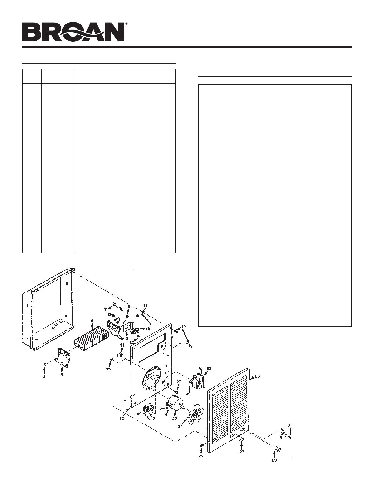
KEY PART
NO. NUMBER PART DESCRIPTION
3 99030190 Fan Delay
4 98006989 Element Bracket (2 Required)
5 99271155 Heating Element (Model 192)
99270723 Heating Element (Model 194)
99270724 Heating Element (Model 198)
6 99400061 Bushing
7 97008688 Black Wire Assembly (29–1/2”)
8 97008690 Black Jumper Wire
9 * Thermal Overload Bracket
10 * Thermal Overload
11 97008692 Red Power Wire
12 99150491 Screw, 8–18 x 3/8 Ph. Pan Head
(14 Required)
13 97008683 Partition Plate Assembly
14 93270619 Wire Clamp ( 3 Required)
15 99260425 Nut, 8–32 Hex Keps (2 Required)
20 99160350 Screw, 6–32 x 1/4 Ph. Pan Head
(2 Required)
21 99030324 Thermostat
22 99080251 Motor (Model 198)
23 99080249 Motor (Models 192 & 194)
24 99020255 Fan Blade
25 97013822 Grille
26 99150478 Screw, 8–18 x 3/8 PH Truss Hd.
(4 Required)
27 99090683 Grille Logo
29 99360136 Knob
30 99110687 Security Cover
31 93150462 Screw, 8–18 x 5/8 Oval Head (2 Required)
* 97013945 Assembly, Thermal Overload (Includes
Key Nos. 9, 10, & 12 (2))
SERVICE PARTS
WARRANTY
BROAN-NUTONE ONE YEAR LIMITED WARRANTY
Broan-NuTone warrants to the original consumer purchaser of its products
that such products will be free from defects in materials or workmanship
for a period of one year from the date of original purchase. THERE ARE NO
OTHER WARRANTIES, EXPRESS OR IMPLIED, INCLUDING, BUT NOT LIM-
ITED TO, IMPLIED WARRANTIES OF MERCHANTABILITY OR FITNESS FOR
A PARTICULAR PURPOSE.
During this one-year period, Broan-NuTone will, at its option, repair or re-
place, without charge, any product or part which is found to be defective
under normal use and service.
THIS WARRANTY DOES NOT EXTEND TO FLUORESCENT LAMP STARTERS,
TUBES, HALOGEN AND INCANDESCENT BULBS, FUSES, FILTERS, DUCTS,
ROOF CAPS, WALL CAPS AND OTHER ACCESSORIES FOR DUCTING. This
warranty does not cover (a) normal maintenance and service or (b) any
products or parts which have been subject to misuse, negligence, accident,
improper maintenance or repair (other than by Broan-NuTone), faulty installa-
tion or installation contrary to recommended installation instructions.
The duration of any implied warranty is limited to the one-year period as
specified for the express warranty. Some states do not allow limitation on
how long an implied warranty lasts, so the above limitation may not apply
to you.
BROAN-NUTONE’S OBLIGATION TO REPAIR OR REPLACE, AT BROAN-
NUTONE’S OPTION, SHALL BE THE PURCHASER’S SOLE AND EXCLUSIVE
REMEDY UNDER THIS WARRANTY. BROAN-NUTONE SHALL NOT BE LIABLE
FOR INCIDENTAL, CONSEQUENTIAL OR SPECIAL DAMAGES ARISING OUT
OF OR IN CONNECTION WITH PRODUCT USE OR PERFORMANCE. Some
states do not allow the exclusion or limitation of incidental or consequential
damages, so the above limitation or exclusion may not apply to you.
This warranty gives you specific legal rights, and you may also have other
rights, which vary from state to state. This warranty supersedes all prior war-
ranties.
To qualify for warranty service, you must (a) notify Broan-NuTone at the ad-
dress or telephone number below, (b) give the model number and part iden-
tification and (c) describe the nature of any defect in the product or part. At
the time of requesting warranty service, you must present evidence of the
original purchase date.
Broan-NuTone LLC
926 W. State Street, Hartford, Wisconsin 53027
www.broan.com 800-558-1711
Product specifications
subject to change
without notice.
99045869A


