Page is loading ...

1
Dear Customer Estimado Cliente
Thank you for selecting our product. We are confident we can fully satisfy Muchas gracias por elegir nuestro producto. Estamos seguros que podemos
your expectations by offering you a wide range of technologically advanced satisfacer completamente sus expectativas ofreciéndole una amplia variedad
products which directly result from our many years of experience in faucet de productos tecnológicamente avanzados que resultan direct
amente de
and fitting production. muchos años de experiencia en grifos y su producción apropiada.
ENGLISH
~
ESPANOL
For easy installation of your
faucet
you will need:
To complete the project, you
should:
You should have the following
tools:
Para la instalación fácil de su grifo
de la
Para terminar el proyecto, usted
debe:
Usted debe tener las herramientas
siguientes:
For care, use soft towel with soap and water only! Under no
circumstances should you use any chemicals.
ATTENTION!
ATENCIÓN!
Para el cuidado, utilice solamente una toalla suave con jabón
y aqua! Bajo ninguna circunstancia no use productos químicos.
Rev. 1 January 2017
IOG 2889.00
JACUZZI
®
JACUZZI
®
usted
ENGLISH
~
ESPANOL
Installation Instructions Instrucciones de Instalación
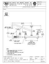
BARREA™ WIDESPREAD LAVATORY FAUCET
BARREA™ GRIFO DE DOS MANILLAS DE EXTENSIÓN
This faucet complies with NSF61/9, ASME/ANSI A112.18.1
and CSA B 125 Standards.
Este grifo se encuentra conforme con losestandares de NSF61/9,
de ASME/ANSI A112.18.1 y de CSA B 125.
to READ ALL the instructions completely before beginning,
to READ ALL the warnings, care and maintenance information.
necesitará:
LEER TODAS las instrucciones completamente antes de comenzar,
LEER TODA la información sobre las advertencias,
cuidado y mantenimiento.
recolectar las herramientas y todas las piezas que usted necesi
tará,
prepare el área para el montaje,
monte el grifo,
conecte las líneas de fuente,
finalmente pruebe y limpie el grifo con un chorro de agua.
gather the t
ools and all the parts you will need,
prepare the mounting area,
mount the faucet,
connect the supply lines,
finally test and flush the faucet.
flat blade screwdriver,
adjustable wrench,
channel pliers,
hex key (included in the box),
®
Teflon tape,
plumbers putty or caulking (silicone).
destornillador plano,
llave ajustable,
alicates acanalados,
llave de tuerca hexagonal (incluido en la caja),
®
cinta adhesiva de Teflon ,
masilla o silicona.
3-1/2”
(88mm)
3-1/4”
(82mm)
2-1/4”
(57mm)
3-7/8”
(99mm)
11/16”
(18mm)
1”
(25mm)
5-3/16”
(132mm)
3-15/16”
(99mm)
6-1/2”
(164mm)
2-1/4”
(57mm)
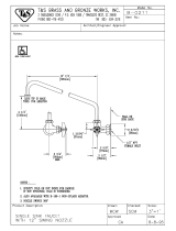
BARREA™ WIDESPREAD LAVATORY FAUCET
BARREA™ GRIFO DE DOS MANILLAS DE EXTENSIÓN
Ø
Ø
2-1/4”
(57mm)
Ø
Ø
Ø
Ø

Installation Instructions Instrucciones de Instalación
This faucet complies with NSF61/9, ASME/ANSI A112.18.1
and CSA B 125 Standards.
Este grifo se encuentra conforme con losestandares de NSF61/9,
de ASME/ANSI A112.18.1 y de CSA B 125.
2
1
36
K1
14
14
15
15
5
20
29
12
12
13L
17
17
13R
6.1
6.2
19
4
3
1
11
11
10
27
28
27
28
9L
9R
18
18
2
31
31
8
7
21
22
23
24
25
26
26
26
28
27
26
28
27
30
32
33
34
32
33
34
16
16
35
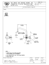
BARREA™ WIDESPREAD LAVATORY FAUCET
BARREA™ GRIFO DE DOS MANILLAS DE EXTENSIÓN
BARREA™ WIDESPREAD LAVATORY FAUCET
BARREA™ GRIFO DE DOS MANILLAS DE EXTENSIÓN
BARREA™ WIDESPREAD LAVATORY FAUCET
BARREA™ GRIFO DE DOS MANILLAS DE EXTENSIÓN
IOG 2889.00
Rev. 1 January 2017

3
Installation Instructions Instrucciones de Instalación
This faucet complies with NSF61/9, ASME/ANSI A112.18.1
and CSA B 125 Standards.
Este grifo se encuentra conforme con losestandares de NSF61/9,
de ASME/ANSI A112.18.1 y de CSA B 125.
20
20
1
2
3
4
5
6.1
7
8.1
9R
9L
10
11
12
13L
15
16
17
18
19
1
2
3
4
5
6.1
7
15
16
17
18
19
21
22
23
24
25
26
21
22
23
24
25
26
2
28
7
28
27
20
1
2
3
4
5
7
15
16
17
18
19
21
22
23
24
25
26
2
28
7
2099140
5007120
2094230
2067150
5007090
5007420
2000160
2236460
2002850
2002840
9917127
9917127
2008330
2008310
2004940
2004970
9903024
2008450
9917058
2016260
2016280N
2016310
2016330
2410080
9916086
2016290
2005490
2004970
ENGLISH
~
ESPANOL
K1
2
30
9
K1
31
32
2
30
9
31
32
29
30
31
32
33
2005480
2002930
2002500
2067200
2901030
SPOUT
SPOUT COLUMN
SPOUT BODY
CONNECTOR
SPOUT BASE
SPOUT KNOB
SPOUT KNOB
AERATOR BODY
AERATOR
VALVE WITH CERAMIC HEAD - RIGHT
VALVE WITH CERAMIC HEAD - LEFT
O-RING
O-RING (2 PCS.)
LEVER (2 PCS.)
LEVER KNOB - RIGHT
LEVER KNOB - LEFT
HANDLE BODY
HANDLE BASE
SCREW (2 PCS.)
HOLE PLUG (2 PCS.)
O-RING
9L
10
11
12
9L
10
11
12
9R
9R
13R
5007000
CAÑO
COLUMNA DE SPOUT
CUERPO DEL CAÑO
CONECTOR
BASE DEL CAÑO
MANIVELA DEL CAÑO
MANIVELA DEL CAÑO
CUERPO DEL AEREADOR
AEREADOR
VÁLVULA (con la cabeza ceramica) - DERECHO
VÁLVULA (con la cabeza ceramica) - IZQUIERDA
JUNTA TÓRICA
JUNTA TÓRICA (2 PIEZAS)
PALANCA (2 PIEZAS)
MANIVELA DEL LA PALANCA - DERECHO
MANIVELA DEL LA PALANCA - IZQUIERDA
CUERPO DE LA PALANCA
BASE DE LA PALANCA
TORNILLO (2 PIEZAS)
OBTURADOR (2 PIEZAS)
JUNTA TÓRICA
33
33
K1
2002900
6.2
6.2
6.1
6.2
14
2002900
9919050
8.1
8.1
8.2 8.2
8.2
20045478
ARANDELA
13L
13R
14
13L
13R
14
THREADED PIPE
NUT
METAL WASHER
RUBBER WASHER
NUT (4 PCS.)
METAL WASHER (4 PCS.)
RUBBER WASHER (4 PCS.)
HOSE G3/4”, 300MM LENGTH
5/64” (2mm) HEX KEY
TUBOS ROSCADOS
TUERCA
ARANDELA DE METAL
ARANDELA DE CAUCHO
TUERCA (4 PIEZAS)
ARANDELA DE METAL (4 PIEZAS)
ARANDELA DE CAUCHO (4 PIEZAS)
MANGUERA G3/4”, LONGITUD DE 300MM
LLAVE ALLÉN 5/64” (2mm)
T-CONNECTION
TUBO EN “T”
O-RING
JUNTA TÓRICA
NOZZLE
LIFT-ROD KNOB
PERILLA DE LA BARRA DE LEVANTAMIENTO
LIFT-ROD
BARRA DE LEVANTAMIENTO
CONE GASKET (2 PCS.)
JUNTA DE CONO (2 PIEZAS)
35
34
36
35
34
36
35
34
36
2002900
2067510
2410490
METAL WASHER (2 PCS.)
ARANDELA DE METAL (2 PIEZAS)
NUT (2 PCS.)
TUERCA (2 PIEZAS)
DRAIN
DRENAJE
LIFT ROD CONNECTION
CONEXIÓN DE LA BARRA DE LEVANTAMIENTO
INYECTOR
WASHER
Ø1-5/16"
( 34mm)Ø
Ø1-5/16"
( 34mm)Ø
Ø1-5/16"
( 34mm)Ø
~ 8" (~ 203mm)
SIZE AND SPACING OF ASSEMBLY OPENINGS
TAMAÑOS Y DISTRIBUCIÓN DE LOS ORIFICIOS DE MONTAJE
SET-UP DIAGRAM
DIAGRAMA DE INSTALACIÓN
2
MAX 1-3/16”
(30mm)
~8"
~(203mm)
Cold water valve is
marked with blue sticker
La válvula de agua fría
está marcada con
le etiqueta azul
Hot water valve is marked
with red sticker
La válvula de agua caliente
está marcada con
le etiqueta roja
NPT 1/2-14
NPT 1/2-14
BARREA™ WIDESPREAD LAVATORY FAUCET
BARREA™ GRIFO DE DOS MANILLAS DE EXTENSIÓN
IOG 2889.00
Rev. 1 January 2017

4
Installation Instructions Instrucciones de Instalación
This faucet complies with NSF61/9, ASME/ANSI A112.18.1
and CSA B 125 Standards.
Este grifo se encuentra conforme con losestandares de NSF61/9,
de ASME/ANSI A112.18.1 y de CSA B 125.
See figs. 1, 3.1-3.4
1.
2.
Veá dis. 1, 3.1-3.4
1.
2.
3.
1
INSTALLATION OF VALVES AND LEVERS
MONTAJE DE VÁLVULAS Y PALANCAS
3.1 3.2 3.3 3.4
MAX. 1-3/16"
(MAX. 30mm)
ENGLISH
~
Check the marker on the valve (see 'Set-up Diagram') to identify the
hot water (red marker) and cold water (blue marker) valves. (fig 2)
Feed the valve (9K) along with the previously attached flange nut
(26), metal washer (27) and rubber washer (28) through the
installation opening in the sink. (fig 3.1, 3.2)
Place the rubber washer (28), metal washer (27) onto the valve
from above and screw on the second flange nut (26), but not too
tightly. (fig 3.2)
ESPANOL
3.
Place the handle base (15) on the mounting surface of lavatory.
Screw on the shroud (14) on the valve (9L), then place the handle
(12,13) on the splines of the valve head, check that the distance 'H'
left (fig. 3.2) is sufficient to allow elements (14) and (12,13) to fit
properly if not, remove elements (15) and (13,14), and adjust the
distance 'H' with the flange nuts (26). (fig. 3.3) After choosing the
appropriate distance 'H', screw home the flange nut (26) (fig 3.3).
Replace the shroud (14) onto the valve (9L) and screw on the shroud
(14) until clear resistance is felt, then place the handle (12,13) in the
appropriate position on the splines of the valve head (9L)(turn the
left handle (item 12, fig. 1) all the way to the left until it is in the OFF
position, the right handle all the way to the right (item 12, fig.1)). After
selecting the appropriate positioning screw home the attaching screw
(16) with the hex key (K1) (included with the faucet). (fig 3.4)
Repeat the above for the second valve and handle.
4.
Compruebe el indicador en la válvula (mire "Diagrama de Instala-
ción”) para identificar la válvula del agua caliente (indicador rojo) y
fría (indicador azul). (dis. 2)
Meta por el agujero de montaje del lavabo la válvula (9L) con la tuerca
de bridas (26) la arandela de metal (27) colocada antes y con la
arandela de goma puesta (28). ( dis. 3.1, 3.2)
Desde arriba ponga una arandela de goma (28) en la válvula (9L) y
desde arriba ponga una arandela de metal (27) y ponga otra tuerca
(26) de bridas, pero no la apriete demasiado. (dis. 3.2)
Ponga base de la volante (15) en la superficie de montaje del
lavabo. Ponga la protección del volante (14) en la válvula (9L),despu-
és ponga la palanca (12,13) en la multicuña de la cabeza de válvula,
compruebe si la distancia „H” (dis. 3.2) es suficiente para garantizar
el encajamiento correcto de los elementos (14) y (12,13) si no
desmonte los elementos (14) y (12,13) corrija la distancia „H” con las
tuercas de bridas (26). (dis. 3.3)
9L
26
28
27
9L
26
27
28
28
27
26
15
14
H=~2-9/16"
(H=~65mm)
4.
5.
6.
5.
6.
ENGLISH
~
ESPANOL
2
SPOUT & CONNECTION INSTALLATION
INSTALACIÓN Y CONECCION DEL GRIFO
1.
2.
3.
1.
2.
3.
4.
4.
See figs. 4, 5 Veá dis. 4, 5
K1
16
1312
Position the spout base (5) on the bath tub ledge.
Insert shank (19) of the spout (A) through center hole of bath tub
ledge. From underneath the ledge place rubber washer (21) and
metal washer (22) on the shank, then screw on the flanged nut
(23). Make sure that the spout (A) is in the correct position. Hand
tighten only the flanged nut (23).
Thread the T-connection (25) on the shank of the spout as shown
in fig. 4
Loop hose (31) as shown in fig. 5 and screw on the hose nut to the
T-connection inlet. Repeat step for second hose (31).
NOTE: Be sure not to kink the hoses.
Posicionar la base del caño (5) en el saliente de la bañera.
Insertar el tubo enroscado (19) del caño (A) a través del saliente del
agujero central de la bañera. Por debajo del saliente colocar una
arandela de goma (21) una arandela de metal (21) sobre el tubo,
luego apretar la tuerca (23). Controlar si del caño (A) se encuentra
en la posición apropiada el saliente de la bañera. Apretar la tuerca
(23) únicamente a mano.
Colocar la conexión T (25) sobre el tubo del
caño como lo
presenta la dis. 4.
Colocar la manguera (31) como lo presenta la fig. 5 y apretarla con
la tuerca de la manguera a la entrada de la conexión T. Repita
el paso
para el segundo manguera (31).
NOTA: Asegurarse de no plegar las mangueras.
Después de elegir la distancia „H”
adecuada, apriete la superior tuerca de bridas (26).
De nuevo ponga la protección de volante (14) en la válvula (9L) y
pong la protección de volante (14) hasta el momento de sentir una
resistencia notable, después ponga la palanca (12,13) en la
multicuña de la cabeza de válvula (9L) en la posición adecuada (dé
una vuelta a la palanca izquierda máximamente a la izquierda, así que
la válvula quede en la posición (posición 12, dis. 1) máximamente a
la izquierda, así que la válvula quede en la posición „CERRADA”, en
caso de la palanca derecha (posición 12, dis. 1) máximamente a la
derecha). Después de elegir la colocación correcta apriete bien el
tornillo sujetador (16) con la llave en forma de la letra “L” con el corte
hexagonal (K1) (adjuntado a la batería) (dis. 3.4).
Todas las actividades mencionadas repita para otra válvula y otro
volante.
Insert nozzle (25) and seal o-ring (24) into T-connection (20).
Inserte el inyector (25) y la empaquetadura de anillo (24) en la
conección „t” (20).
BARREA™ WIDESPREAD LAVATORY FAUCET
BARREA™ GRIFO DE DOS MANILLAS DE EXTENSIÓN
IOG 2889.00
Rev. 1 January 2017

5
Installation Instructions Instrucciones de Instalación
This faucet complies with NSF61/9, ASME/ANSI A112.18.1
and CSA B 125 Standards.
Este grifo se encuentra conforme con losestandares de NSF61/9,
de ASME/ANSI A112.18.1 y de CSA B 125.
5
4
A
5
20
31
31
9R
9L
19
21
22
20
23
24
25
See fig. 6
Dismantle the drain assembly to the parts shown on fig. 6.
Insert collar gasket (4) and drain collar (3) into drain hole of a
lavatory. From underneath the lavatory slip under-bowl gasket (5)
into drain collar (3), washer (6) and flanged nut (7).
Position under-bowl gasket (5) correctly under the lavatory and
screw flanged nut (7) firmly but do not overtighten.
Make sure washer (8) is inside drain body (9) and screw drain body
(9) onto drain collar (3) hand tighten only.
Pay attention to align the drain body (9) so that the horizontal hole
of drain body will be in the same plane as a lift rod ( 30, fig.1).
Tighten drain body (9) onto drain collar (3) and tighten the flanged
nut (7).
1.
2.
3.
4.
5.
Veá dis. 6
Desmontar las piezas del drenaje según lo demostrado en la dis. 6.
Inserte la empaquetadura superior (4) y el tapon del drenaje (3) en
el agujero del drenaje de un servicio. Colaque por debajo del
lavatorio la empaquetadura inferior (5) en el collar del drenaje (3),
la arandela (6) y tuerca de montaje (7).
Coloque la empaquetadura inferior (5) correctamente debajo del
servicio y entornille a tuerca de montaje (7) firmemente pero no
apriete demasiado.
Cerciorese de que la arandela de tubo (8) este en el cuerpo del
drenaje (9) y entornille el cuerpo del drenaje (9) en el collar del
drenaje (3) apriete solamente con la mano.
Preste atención en alinear el cuerpo del drenaje (9) de modo que el
agujero horizontal del cuerpo del drenaje esté en el mismo plano
que la varilla elevadora ( dis. 1, elem. 30 ). Apriete el cuerpo
del drenaje (9) sobre el collar del drenaje (3) y apriete la tuerca de
montaje (7).
ENGLISH
~
ESPANOL
1.
2.
3.
4.
5.
DRAIN ASSEMBLY INSTALLATION INSTALACIÓN DEL DRENAJE
3
6.
7.
8.
9.
10.
6.
7.
8.
9.
10.
Insert drain plug (2) into drain collar (3).
Remove clip (15) from ball rod (12); undo a ball rod nut (13)
from body, take out sealing washer (11) from a nut and push the
nut forward over ball rod (12) from the longer end with the thread
facing a ball.
Insert the sealing washer (11) and the ball rod (12) into a side hole
of drain body (9). Make sure that the rod ending goes under the
plug screw head.
Tighten ball rod nut (13) making sure that the ball rod seat (11)
and ball joint are properly installed.
®
Add Teflon tape to tail tube (10), and mount tail tube to drain
body (9).
Lift the drain plug (2) to an open position, by lowering the horizontal
ball rod (12) down.
Insert lift rod (30, fig.1) down through faucet base (3, fig.1)
and top of lift rod strap (14). Adjust to proper height and tighten
screw (16).
Choose the position of horizontal ball rod (12) in one of the holes in
lift rod strap (14). Insert horizontal ball rod (12) through one arm
of spring clip (15) and lift rod strap (14) and then second arm of
spring clip (15).
Try if a drain plug (2) closes the drain by pulling the lift rod. If not,
make corrections of position of lift rod strap (14) and horizontal ball
rod (12).
11.
12.
13.
14.
Inserte el tapón de drenaje (2) en el collar del drenaje (3).
Quite el clip de la abrazadera de muelle
(15) de varilla de bola (12);
retire la tuerca de varilla de bola (13) del cuerpo, tome hacia fuera
el arandela selladora (11) a lo largo de varilla de bola (12) del
extremo más.
Inserte el arandela selladora (11) y el varilla de bola (12) en un
agujero lateral del cuerpo del drenaje (9). Asegúrese de que el
extremo de la barra va debajo de la cabeza del tornillo del tapón.
Ajuste la tuerca de varilla de bola (13) serciorandose de que el
asiento de la barra del pivote (11) yel cuerpo del drenaje este
instalado correctamente.
®
Enrrollar la cinta de Teflon para asegurar el pipa de descarga (10),
monte colillo al cuerpo del drenaje (9).
Levante el tapón de renaje (2) a la posición de abierto, moviendo
el varilla de bola (12) hacia abajo.
Inserte la varilla elevadora (dis. 1, elem. 30) por el agujero
en base del grifo (dis. 1, elem.3) y inserte el plato de
ajustamiento (14). Ajuste a la altura apropiada y apriete el tornillo
(16).
Elija la posición de varilla de bola (12) en uno
de los agujeros del
plato de ajustamiento (14). El varilla de bola (12) a través de la
broche (15) y levante el plato de ajustamiento (14) y despues el
segundo brazo de la broche (15).
Intente cerrar con el tapón de drenaje (2)
tirando de la varilla de
elevación. Si no es posible, haga las correcciones de la posición del
plato de ajustamiento (14) y de la barra horizontal de varilla de
bola (12).
d
11.
12.
13.
14.
BARREA™ WIDESPREAD LAVATORY FAUCET
BARREA™ GRIFO DE DOS MANILLAS DE EXTENSIÓN
IOG 2889.00
1/2 1/2
Rev. 1 January 2017

6
4
It is recommended that every 3-6 months (depending on water quality)
you remove the aerator (item 8.1, fig. 1) from the faucet spout (1) in order
to remove any impurities.
Una vez a 3-6 meses (dependiendo de la calidad del agua) se recomienda
quitar el difusor (pos. 8.1 dis. 1) del caño de la mezcladora (1) con el fin de
limpiarlo de todo tipo de ensuciamiento.
OPERATING INSTRUCTIONS LA DESCRIPCIÓN DEL FUNCIONAMIENTO
Water flow is turned on and adjusted using the handles. The faucet is fully
open when you turn the handles through a 90 angle (1/4 of a turn):
• clockwise – for the cold water handle located on the right,
• counterclockwise – for the hot water handle located on the left.
Water flow rate is adjusted within the quarter turn range.
Para abrir la salida y el ajuste de flujo de agua sirven los mangos.
Apertura total sucede como consecuencia de girar los mangos por el
ángulo de 90 (1/4 de giro):
• en la dirección de las manillas del reloj – en caso de mango del agua
fría colocado en la parte derecha,
• en la dirección opuesta a las manillas del reloj – en caso de mango
del agua caliente colocado en la parte izquierda.
Ajuste de flujo del agua sucede en 1/4 de giro.
See fig. 1
1.
2. Turn on hot and cold water supply valves and flush water lines for 15
1)
seconds .
3. Check all connections at arrows for leaks. Re-tighten if necessary, but
do not overtighten.
4.
1)
IMPORTANT: This flushes away any debris that could cause damage to
internal parts.
Ver la figura 1
1.
2. Abra las válvulas de suministro de agua fría y caliente y enjuague las
1)
lineas de agua por 15 seg. .
3. Chequee todas las conecciones para ver si hjay fuga de agua. Reajuste
si es necesario, pero no ajuste demasiado.
4.
1)
IMPORTANTE: Esto limpia los residuos que podrían causar daño a las
piezas internas con un chorro de agua.
5
AFTER INSTALLATION BEFORE USE
DESPUES DE LA INSTALACIÓN Y ANTES DEL USO
ENGLISH
~
ESPANOL
ENGLISH
~
ESPANOL
Installation Instructions Instrucciones de Instalación
This faucet complies with NSF61/9, ASME/ANSI A112.18.1
and CSA B 125 Standards.
Este grifo se encuentra conforme con losestandares de NSF61/9,
de ASME/ANSI A112.18.1 y de CSA B 125.
Remove body of aerator (7), aerator insert (8.1)
and
turn faucet
lever handles all the way on.
Quite el aereador (7) , el relleno del aerador (8.1)
y
gire las manillas
a la posición de abierto.
Next aerator insert (8.1) and body of aerator (7) .
Hand
tighten only.
Seguidamente remplace , el relleno del aerador (23)
y el aereador
(16)
.
Ajuste solamente con la mano .
PROTECTIVE CAP
DRAIN PLUG
DRAIN COLLAR
COLLAR GASKET
UNDER-BOWL GASKET
WASHER
FLANGED NUT
WASHER
DRAIN BODY
DISCHARGE PIPE
SEALING WASHER
BALL ROD
BALL ROD NUT
ADJUSTMENT PLATE
CLIP
SCREW
1
2
3
4
5
6
7
8
9
10
11
12
13
14
15
16
TAPA PROTECTORA
TAPÓN DE DRENAJE
COLLAR DE DRENAJE
EMPAQUETADURA SUPERIOR
EMPAQUETADURA INFERIOR
ARANDELA DE MONTAJE
TUERCA DE MONTAJE
ARANDELA DE TUBO
CUERPO DE DRENAJE
PIPA DE DESCARGA
ARANDELA SELLADORA
VARILLA DE BOLA
TUERCA DE VARILLA DE BOLA
PLATO DE AJUSTAMIENTO
BROCHE
TORNILLO
LIFT ROD CONNECTION
(fig.1, item 35)
CONEXIÓN DE LA BARRA DE LEVANTAMIENTO (35, dis.1)
ENGLISHENGLISH
~
ESPANOL
6
1
2
3
4
5
6
7
8
9
10
11
12
13
14
15
16
e
.
replace
BARREA™ WIDESPREAD LAVATORY FAUCET
BARREA™ GRIFO DE DOS MANILLAS DE EXTENSIÓN
IOG 2889.00
Rev. 1 January 2017

7
All dimensions and drawings are for reference only. For details, please refer to actual products.
Todas las dimensiones y dibujos sirven únicamente de referencia. Para consultar detalles, ver los productos.
Installation Instructions Instrucciones de Instalación
This faucet complies with NSF61/9, ASME/ANSI A112.18.1
and CSA B 125 Standards.
Este grifo se encuentra conforme con losestandares de NSF61/9,
de ASME/ANSI A112.18.1 y de CSA B 125.
7
CARE AND MAINTENANCE
CUIDADO Y MANTENIMIENTO
Your Jacuzzi product is designed and engineered in accordance with the
highest quality and performance standards. Be sure not to damage the
finish during installation. Care should be given to the cleaning of this
product. Although its finish is extremely durable, it can be damaged by
harsh abrasives or polish. Never use abrasive cleaners, acids,
solvents, etc. to clean any Jacuzzi product. To clean, simply wipe
gently with a damp cloth and blot dry with a soft towel.
Su producto de la Jacuzzi está diseñado y dirigido acuerdo con los
estándares de funcionamiento y calidad más altos. Este seguro no
dañar las terminaciones del grifo durante la instalación. Cuide el
producto manteniendolo siempre limpio. Aunque su acabado es
extremadamente durable, puede ser dañado por los abrasivos o
pulientes ásperos. Nunca utilice limpiadores abrasivos, ácidos,
solventes, etc. para limpiar cualquier producto de la Jacuzzi.
Para limpiar, simplemente use un paño húmedo y seque con
una toalla suave.
®
®
®
®
6
ENGLISH
~
ESPANOL
ENGLISH
~
ESPANOL
Warranty conditions and warranty registration card are outlined on a
separate sheet.
Las condiciones de la garantía y la tarjeta del registro de la garantía
se encuentran en una pagina separada.
BARREA™ WIDESPREAD LAVATORY FAUCET
BARREA™ GRIFO DE DOS MANILLAS DE EXTENSIÓN
IOG 2889.00
Rev. 1 January 2017
/