Miller Coolmate 3.5 Owner's manual
- Category
- Welding System
- Type
- Owner's manual
This manual is also suitable for
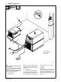
Miller Coolmate 3.5: Cool your welding equipment with this industrial-grade recirculating coolant system. With a maximum cooling capacity of 14,000 BTU/hr, it's ideal for water-cooled GTAW torches and GMAW guns rated up to 600 amps. Its 3.5-gallon tank and efficient pump ensure a steady flow of coolant, while its compact design and durable construction make it easy to use and transport.
Miller Coolmate 3.5: Cool your welding equipment with this industrial-grade recirculating coolant system. With a maximum cooling capacity of 14,000 BTU/hr, it's ideal for water-cooled GTAW torches and GMAW guns rated up to 600 amps. Its 3.5-gallon tank and efficient pump ensure a steady flow of coolant, while its compact design and durable construction make it easy to use and transport.


-
 1
1
-
 2
2
-
 3
3
-
 4
4
-
 5
5
-
 6
6
-
 7
7
-
 8
8
-
 9
9
-
 10
10
-
 11
11
-
 12
12
-
 13
13
-
 14
14
-
 15
15
-
 16
16


Miller Coolmate 3.5 Owner's manual
- Category
- Welding System
- Type
- Owner's manual
- This manual is also suitable for
Miller Coolmate 3.5: Cool your welding equipment with this industrial-grade recirculating coolant system. With a maximum cooling capacity of 14,000 BTU/hr, it's ideal for water-cooled GTAW torches and GMAW guns rated up to 600 amps. Its 3.5-gallon tank and efficient pump ensure a steady flow of coolant, while its compact design and durable construction make it easy to use and transport.
Ask a question and I''ll find the answer in the document
Finding information in a document is now easier with AI
in other languages
Related papers
-
Miller LJ450119F Owner's manual
-
-
-
-
-
-
-
-
-