Page is loading ...

SINGLE SEAL PUMPS DOUBLE SEAL PUMPS
OWNER’S MANUAL
Waste Handling Sump Pumps
© 2014 Pentair Ltd. All Rights Reserved. 23833A201 (03/27/14)
293 WRIGHT STREET, DELAVAN, WI 53115 WWW.FEMYERS.COM
PH: 888-987-8677

2
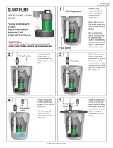
TYPICAL SECTIONAL DRAWINGS
FOR WHR/WHRH AND WHRE
SINGLE AND DOUBLE SEAL WASTE HANDLING PUMPS
SINGLE SEAL
FIG. 1
DOUBLE SEAL
FIG. 2
WHR
WHRH
WHRE
WHR-DS WHR-SD L/D
WHRH-DS WHRH-DS L/D
WHRE-DS WHRE-DS L/D

3
GENERAL DESCRIPTION AND USES
The WHR and WHRH Series are solids handling pumps that
can be used to pump RAW SEWAGE for COMMERCIAL and
DOMESTIC use, but are not intended to handle large rags,
mop heads, or strings. All pumps can be used for normal
sump duty where extra capacity is required. The WHRE
Series is for pumping sump water and EFFLUENT from
septic tanks only. DO NOT USE FOR RAW SEWAGE.
RECESSED IMPELLERS
All of the pumps are of the recessed impeller type that
provides a clear volute passage for solids as no solids pass
through the impeller. All of the pumps listed can be used to
pump septic tank EFFLUENT or GROUND sewage as used
in some pressure sewer systems.
DESIGN OF PRESSURE SEWER SYSTEMS
MYERS has available complete computer SOFTWARE for
designing PRESSURE SEWER SYSTEMS. This gives pipe
sizes to use and gives exact flow from any pump or group
of pumps in the system when operating simultaneously. This
design DISK for IBM or COMPATIBLE computers is available
to engineers on request.
DOUBLE SEAL PUMPS
All double seal models have two seals with an oil chamber
between the seals so that seal faces of both lower and upper
seals are oil lubricated for longer life and greater protection
against water leaking into the motor windings. These double
seal units are made with and without a seal leak probe. The
leak probe in the oil seal chamber detects any water leakage
into the chamber and turns on a red signal light in the control
panel. Pumps should be removed from sump and seals
replaced after seal light shows in the panel. Control panels
must be used for pumps having the seal leak probe.
Double seal pumps without the seal leak probe, should be
pulled and seal leak checked in 12 to 18 months.
LEVEL CONTROLS
All pumps must use sealed level control switches for
automatic operation. MLC and MFLC controls have sealed
mercury switches that are 1 H.P. rated at 230 volts. ALC and
AWS-1 controls have sealed mechanical switches that are
rated 2 H.P. at 230 volts.
Simplex single phase pumps can be made automatic by
attaching MFLC or MLC controls to pump. These switches
have a fixed draw off level of 8 to 10” and can be used up to
1 H.P. For higher H.P. ratings two mercury switch (or SMNO)
controls with a magnetic starter can be used.
The ALC and AWS-1 controls can be used for simplex single
phase pumps with ratings up to 2 H.P.
All duplex systems must use pilot mercury control sensor
switches with control box and magnetic starters.
Plug in cords can be used on all the single phase pumps
without seal leak detector. The cord has a GROUND pin that
plugs into a grounded receptacle. The grounded receptacle
cannot be used in the wet sump or basin due to DANGER of
current leakage.
Sealed junction boxes must be used in wet sumps or basins
to make connections to motor cord. The AWS-1 control also
acts as a sealed junction box for connecting power cord to
pump cord.
SAFETY WARNING
All pumps single or three phase must have a GROUND
WIRE that is connected to a screw in the metal pump
housing. This wire goes to the control box and is connected
to a good outside GROUND such as a metal water pipe or
GROUND STAKE driven at least 6 feet into the ground.
MOTOR TYPES
All single phase pump motors are of the permanent split
capacitor type that do not require a start switch or start relay.
Automatic reset overload switches are attached directly to the
motor windings.
Three phase pump motors require a magnetic starter with 3
leg overload protection.
INSTALLATION
Pumps can be installed inside sealed basin with proper
venting for either simplex or duplex systems. SIMPLEX or
DUPLEX basin systems are available. See Figs. 3 and 4.
It is not recommended that basins be used for RAW
SEWAGE inside the home, but are for use in office buildings
and small industrial buildings and factories.
Basins can be used inside the home where extra capacity
sump pumps are required for water softeners and wash
water.
If raw sewage must be pumped in the home use outside
basins that connect with pressure sewer mains or gravity
sewers, or run to septic tanks.
If an inside basin is used it is usually installed at time of
pouring the concrete floor.
Pumps can be installed in a compartment of septic tanks
for pumping to pressure sewer mains, gravity sewers, leach
fields, or evaporation mounds. See Figs. 5, 6 and 7.
PROPER VENTING FOR BASINS
INSTALLED INSIDE
All inside sealed basins must have a 2” or 3” vent pipe
installed in accordance with local codes. Sumps for handling
softener water, wash or drainage water do not have to be
sealed or vented.
Outside basins are usually of fiberglass and from 4 to 8 feet
deep and have a sealed cover. Pump is usually installed
with a lift out rail system so that pump can be removed
without disturbing the discharge piping. The check valve
comes out with pump for servicing. Complete LIFT OUT
SYSTEMS mounted in fiberglass basins are available to meet
customer’s specifications.
Sump basin must be vented in accordance with
local plumbing codes. These pumps are not designed for and
CANNOT be installed in locations classified as hazardous in
accordance with the National Electric Code ANSI/NFPA 70.

4
SIMPLEX SYSTEM WITH
ALC LEVEL CONTROLS.
FIG. 3
DUPLEX SYSTEM WITH
MERCURY FLOAT OR
SMNO CONTROLS AND
REMOTE CONTROL BOX.
FIG. 4

5
PIPING
Pumps are fitted with 2” or 3” female threaded pipe flange.
Galvanized or PVC plastic pipe can be used. Plastic pipe is
preferred for raw sewage or septic tank effluent.
CHECK VALVES AND SHUT-OFF VALVES
All pumps must have check valves and shut-off valves in
the discharge line. Check valves must be flapper type with
outside spring or ball type. Shutoff valves can be ball or gate
type. Plastic construction for both check and shut-off valves
is preferred.
STARTING SIMPLEX SYSTEMS
1. For single phase pumps with MLC or MFLC control,
plug cords piggy back into receptacle and run water into
sump until pump starts. Allow pump to make several on/
off cycles. Leave power cord plugged in. If pump runs
but does not pump it may be air locked. Unplug cord and
crack union in the discharge line then restart pump, this
should vent off any trapped air. Re-tighten union.
2. With 2 “mercury” controls turn on power at the control
box and run water into sump. When level gets above top
control pump should start and continue to pump until
level drops to lower control stopping pump. Run pump
through several cycles. If pump runs but does not pump,
check air lock as in 1. Leave power on for automatic
operation.
3. Where ALCL or AWS-1 controls are used plug in cord
or turn on power and run water into sump, when level
is about half way up on upper weight pump should start
and run until level drops until about half the lower weight
is above water, stopping pump. Check 1, if pump does
not operate properly. For all cases if motor does not start
when water level is up check for proper plug in or that
start switch is on, or if fuse is blown. ALWAYS HAVE
ELECTRICTIAN MAKE ELECTRICAL CHECKS.
STARTING PUMP “WHE-P” (AUTOMATIC)
USING MECHANICAL SWITCH WITH
SERIES PLUG-SIMPLEX SYSTEM
1. These pumps have a mechanical (mercury-free) float
switch with a 20 ft. cord and 115 volt or 230 volt series
piggy-back plug on ½ H.P. with switch mounted to the
pump. On ¾ H.P. and 1 H.P., it requires 20 ft. cord and
230 volt only.
2. Plug the switch cord plug into a proper voltage properly
grounded outlet.
3. Plug the pump power cord into the back of the switch
cord series plug.
4. Tape the cords to the discharge pipe every 12”.
5. Run water into sump until pump starts. Be sure
discharge line valve is open.
6. Allow pump to operate through several on/off cycles.
7. If pump does not operate properly, see trouble shooting
service chart for remedy.
HOW TO SET CONTROLS AND START
DUPLEX SYSTEMS
CONTROL BOX MUST BE USED ON ALL DUPLEX
SYSTEMS
1. 4 “mercury” controls are used for duplex systems. Set
turn-on control 6” to 8” above pumps. Set turn-off control
8” to 10” above bottom of sump. Set override control 6”
to 8” above turn-on control. Set high level alarm control
about 6” to 8” above override control. Mark all control
cords so that they can be connected correctly in the
control box. See Fig. 4.
2. Turn Hand-Off-Auto switches to OFF position and close
circuit breaker.
3. Turn H-O-A switches to the AUTO position and run
water into sump. When level floats up and activates the
turn-on switch one pump should start and run, pump will
continue to run until lower control is exposed stopping
pump.
4. Run water into sump again and when level floats up
turn-on control, opposite pump will start and run until
level drops exposing lower control, stopping pump.
5. Run this test several times to be sure pumps are
alternating properly.
LEVEL CONTROL SYSTEMS AVAILABLE
1. Simplex single phase packaged automatic system.
This system has the MLC or MFLC mercury float
switch attached directly to the pump. This system has a
fixed pump-off level of 8” to 10” and is usually used for
drainage water and is good up to and including 1 H.P.
2. Simplex single phase pumps can use the ALC or AWS-1
controls which are mounted separate from the pump.
These controls can be used up to 2 H.P. motors. See Fig.
3
3. Simplex pumps can use two “mercury” controls mounted
separate from the pump. These controls must be used
with a control box and magnetic contactor. These
controls can be spaced apart for any draw off level
required and can be used for 2 H.P. or larger motors.
4. Duplex pump systems must use only the “mercury”
controls with electrical control box. These control boxes
mounted remote from the sump tank are generally of plastic
construction for best corrosion resistance. See Fig. 4.
AIR LOCKING
A sump pump is said to be air locked if water traps
in the pump and it cannot get out, thus preventing
pump from operating. ALL MYERS SUMP PUMPS
HAVE A SMALL AIR VENT HOLE IN THE IMPELLER
CHAMBER TO LET OUT TRAPPED AIR. IF THIS HOLE
BECOMES PLUGGED, PUMP MAY AIR LOCK. THIS
USUALLY HAPPENS ON PUMPS THAT ARE USED
MAINLY IN THE SEASONS. IN SUMMER MONTHS,
THE PUMP MAY BE TURNED OFF AS SUMP WATER
DRIED UP. WHEN PUMP IS TURNED ON AGAIN AND
WATER COMES UP IN SUMP, THE AIR WILL TRAP IN
PUMP IF NOT VENTED.
AS A SECONDARY PRECAUTION IN INSTALLATIONS
OF THIS TYPE – 1/8” HOLE SHOULD BE DRILLED
IN THE DISCHARGE PIPE BELOW THE CHECK
VALVE. THE CHECK VALVE SHOULD BE 12 TO 18
INCHES ABOVE PUMP DISCHARGE. DO NOT PUT
CHECK VALVE DIRECTLY INTO PUMP DISCHARGE
OPENING.
In normal sumps where the pump is operating daily, air
locking rarely occurs.

6
MOTOR OVERLOAD PROTECTION
All single phase motors have built-in automatic reset
overload switches fastened directly to the motor windings.
All 3 phase motors must be installed with magnetic starters
having 3 leg overload protection.
HOW TO SET CONTROLS AND START
SIMPLEX SYSTEMS
1. Automatic systems – These systems have the MLC,
MFLC, or ALC switches mounted on the pump, so pump
is installed in the sump and motor cord is plugged into
GROUNDED receptacle. For sealed sump cover, power
cord is brought through a split rubber plug in the sump
cover.
2. Where 2 “mercury” controls are used the turn on control
is set 3” to 6” above top of motor, and the turn-off control
is set about 6” to *’ above bottom of sump. If a high level
alarm control is used it is set about 6” above upper
control. If sump depth will not allow these settings closer
spacing can be used.
3. Where ALLC or AWS-1 controls are used the
DISPLACEMENT WEIGHTS are set so that turnon
weight is 4” to 6” above top of motor and lower weight is
set about 6” above sump bottom.
4. Repeat this operation with one pump off which will
duplicate a failed pump condition. When the level
reaches the override control the pump that is turned on
should start and run and pump down sump level.
5. To check high level alarm, again turn both switches to
OFF and fill sump until level is above the alarm control.
Turn switches to Auto position and ALARM BUZZER
should sound and alarm light should come on. When
level drops below the alarm control buzzer should stop.
6. If pumps operate as described then set both H-O-A to
Auto and pumps are ready to operate automatically.
7. If pumps do not operate properly then check as
described for simplex systems. See page. 13.
NEVER WORK ON PUMPS OR CONTROL
BOXES UNTIL CIRCUIT BREAKERS ARE TURNED OFF.
Always have a qualified ELECTRICIAN make electrical
connections and service checks.
SPECIAL INSTRUCTIONS FOR THREE
PHASE PUMPS
1. Only qualified persons shall conduct
services and installations of this pump. The pump
must be wired by a qualified electrician, using an
approved starter box and switching device.
Risk of electric shock. Do not connect
conduit to pump
2. Three phase pumps are always installed with control
boxes having magnetic starters with 3 leg overload
protection. DO NOT TRY TO RUN THREE PHASE
PUMPS DIRECTLY ACROSS THE LINE.
3. To Connect Pump: Run wire from pump to the bottom
of control box or appropriate junction box suitable for
enclosing splice connections. A hole must be cut into the
control box for the wires. With power to control box off,
connect green (ground) line to ground lug. Connect black
(power) wires to power lead terminals. Make sure that all
wires are inside control box and not in a position to be
pinched or shorted when the door is closed. See wiring
diagrams, page 8.
4. All three phase motors can run either direction,
ROTATION can be changed by interchanging any two
line leads at magnetic starter. BE SURE CIRCUIT
BREAKER IS OFF BEFORE MAKING THIS CHANGE.
To find if rotation is correct operate pumps and check
delivery operation. If flow and head is low (refer to pump
curves shown in this manual) the rotation is wrong.
With duplex pumps check operation of both pumps.
All pump impellers either single or three phase must
turn counterclockwise when looking into pump inlet. If
uncertain of rotation, TURN OFF POWER and lift pump
from basin with cord connected and lay pump on side
so impeller can be seen. Turn on power and start pump
using hand position of H-O-A switch. Turn on and off
fast so that coast of impeller can be seen. NEVER PUT
HAND OR FINGERS ON THE IMPELLER. Interchange
any two line leads at the magnetic starter to change
rotation.

7
SINGLE SEAL PUMPS AND DOUBLE SEAL PUMPS
WITHOUT SEAL LEAK PROBE
DOUBLE SEAL PUMPS WITH SEAL LEAK PROBE
(RED CONDUCTOR IN POWER CORD
IS FOR SEAL LEAK PROBE)
WIRING DIAGRAMS SINGLE PHASE MOTORS
SINGLE PHASE PUMPS
Risk of electric shock. This pump is supplied with a grounding conductor and grounding-type attachment plug. To
reduce the risk of electric shock, be certain that it is connected only to a properly grounded, grounding-type receptacle.
WIRING DIAGRAMS FOR 3 PHASE MOTORS
FOR SINGLE SEAL PUMPS AND DOUBLE SEAL PUMPS
WITHOUT SEAL LEAK PROBE

8
PERFORMANCE CURVES
PERFORMANCE CURVE
WHR SERIES WASTE HANDLING PUMPS
PERFORMANCE CURVE
WHRE SERIES EFFLUENT PUMPS
PERFORMANCE CURVE
WHRH SERIES WASTE HANDLING PUMPS

9
FIG. 5 PUMP IN SEPARATE TANK PUMPING TO SEEPAGE MOUND

10
FIG. 6 PUMP INSTALLED IN FIBERGLASS BASIN AT OUTLET OF SEPTIC TANK
USED WHEN PUMPING INTO PRESSURIZED SEWER MAIN OR LEACH FIELD
FIG. 6

11
FIG.7 PUMP AND CONTROLS INSTALLED DIRECTLY IN SEPTIC TANK
USED WHEN PUMPING INTO PRESSURIZED MAIN OR LEACH FIELD
FIG. 7

12
POINTS TO CHECK IF PUMP DOES NOT
RUN OR DOES NOT RUN PROPERLY
1. Pump does not run or start when water is up in sump.
a. Check for blown fuse or tripped circuit breaker.
b. Check for defective level switch.
c. Where control panel is used be sure H-O-A switch is
in the Auto position. Turn switch to the HAND position
and if pump runs then trouble is in the automatic
electrical system. Have an ELECTRICIAN make
electrical checks.
d. Check for burned out motor. Occasionally lightning
can damage a motor even with lightning protection.
e. Where plug-in cords are used be sure contract blades
are clean. DO NOT USE PLUG-IN CORDS INSIDE A
SUMP OR WET WELL.
2. Pump runs but does not deliver flow.
a. Check for air lock. Start and stop pump several times
if this does not help it may be necessary to loosen a
union in the discharge line to relieve air lock.
b. Check valve may be installed backward. Check flow
arrow on valve body. Check shut-off valve it may be
closed.
c. Check vertical elevation, it may be higher than pump
can develop. (See pump curve.)
d. Pump inlet may be plugged with a rag or trash.
Remove pump to check.
e. If pump is three phase be sure pump rotation is
correct. (See instructions for checking rotation.)
f. Level control ball or weight may be stuck on side of
basin. Trash may be stuck on ball preventing it from
floating up.
ALWAYS UN-PLUG CORD OR TURN OFF
CIRCUIT BREAKER BEFORE DOING ANY WORK ON
THE PUMP. If control panel is remote from pump, disconnect
lead wires to motor so that someone cannot turn the circuit
breaker back on. If motor is three phase mark the leads so
they can be replaced in same order.
DISMANTLING PUMP FOR
REPLACEMENT OF PARTS
Clean pump thoroughly. Knock off all scale and deposits.
Use sandblast if possible. Submerge complete unit in bleach
solution for one hour before taking apart.
TO REPLACE CAPACITORS ONLY
The motors on all WHR, WHRH and WHRE series single
phase pumps are of the permanent split capacitor type, so
have no relays or starting switch, and have only a starting
capacitor that is in the circuit for both starting and running
conditions.
1. Remove oil fill plug in top of motor and pour out oil. Fig. 8
2. Remove bolts from capacitor housing and bump housing
with plastic hammer to loosen. Fig. 9
3. Lift housing and disconnect motor leads and capacitor
wires. Fig. 10
4. Remove capacitor clamp and slide out capacitor.
Replace with new capacitor and re-connect. Fig. 11
Wiring connections are given in these instructions.
5. Replace capacitor housing, be sure rubber seal ring is in
place. Fig. 12
6. Refill motor with Myers submersible motor oil, DON’T
OVER FILL WITH OIL. OIL LEVEL SHOULD BE ONE
INCH FROM TOP OF CASTING. Fig. 13
7. Be sure pump turns free before plugging into power.
Turn pump on side and turn impeller, using screwdriver
in slotted shaft.
Plug pump into receptacle to test operation. Pump must
run quiet and free of vibration.
FIG. 8
FIG. 9

13
FIG. 10 FIG. 12
FIG. 11
FIG. 13

14
TO REPLACE POWER CORD ONLY
1. Remove capacitor housing as described above.
Disconnect cord leads from motor and remove ground
screw.
2. Unscrew cord bushing and remove from housing. Fig. 14
3. Replace with new fitting and cord, be sure “O” ring seal
is in place. Fig. 14
4. Replace ground screw and re-connect motor wires.
Wiring diagram is given in these instructions.
5. Replace capacitor housing and refill motor with Myers
submersible oil. See Fig. 13 for oil level. One inch from
top of casting.
COMPLETELY DISMANTLE PUMP TO
REPLACE MOTOR STATOR AND SEAL
1. Pour oil from motor and remove capacitor housing as
described above.
2. Remove bolts from motor housing only. Do not remove
bolts that hold motor plate to volute case. Fig. 15
3. Lift off motor housing, pry between ears to loosen.
Fig. 16
4. Remove case holding bolts and lift out rotating unit. Pry
between ears to loosen. Fig. 17
5. Hold rotor and unscrew impeller locking nut. Turn
counter-clockwise as thread is right hand. Fig. 18.
6. Unscrew impeller, turn counter-clockwise to loosen.
Fig. 19
7. Pry off seal with screwdrivers. It is not important if seal is
damaged, as it must be replaced. Replace both parts of
seal, never one or the other. Fig. 20.
FIG. 14
FIG. 15
FIG. 16
FIG. 17

15
FIG. 18
FIG. 20
FIG. 19
FIG. 21
8. Bump shaft on end with plastic hammer to push ball
bearing from lower motor plate. Fig. 21.
9. Clean seal cavity thoroughly before replacing ceramic
seal. Use grease on rubber cup of seat and push into
housing, use plastic rod to push into place. Clean seal
face to remove any speck of dirt, and use light oil on
face before installing bellows part of seal. Fig. 22

16
10. If necessary to replace ball bearing, press off in arbor
press. Use strips of metal between bearing and rotor to
press off. Fig. 23. Always press on inner race of bearing
when replacing.
11. If necessary to replace motor stator, use new housing
with stator pressed in. Both housing and stator must be
replaced as a unit, as stator is pressed in at factory and
is not to be replaced in the field. Fig. 24
12. In reassembly, be sure rubber seal ring and thrust
washer are in place as shown. Fig. 25
FIG. 22
FIG. 23
FIG. 24
FIG. 25

17
SPECIAL INSTRUCTIONS FOR
REPLACING SEALS IN
DOUBLE SEAL PUMPS
1. Remove plugs in motor housing and in seal housing and
drain oil.
2. Remove bolts in lower plate only.
3. Lift off pump case.
4. Hold impeller and unscrew holding nut. Hold shaft with
screwdriver and unscrew impeller, turn counterclockwise.
5. Pry off seal bellows and ceramic seat. Break seats if
necessary to get out as they must be replaced with new
parts.
6. NEVER USE OLD SEAL PARTS. USE ONLY
COMPLETELY NEW SEALS.
7. Remove snap ring with snap ring pliers.
8. Pry off upper seal bellows and ceramic seat.
9. If no water has entered motor housing (check winding
with ohmmeter or megger) wipe seal chamber
thoroughly and replace seals.
10. Replace oil in motor housing and seal chamber. Use
only MYERS submersible oil.
11. If water has been in motor then remove seal chamber
and lift out rotor unit and remove motor stator. See single
seal instructions for replacing ball bearing and motor
stator.
FIG. 26

18
PUMP DIMENSIONS

19

20
LIMITED WARRANTY
F.E. MYERS warrants to the original consumer purchaser (“Purchaser” or “You”) of the products listed below,
that they will be free from defects in material and workmanship for the Warranty Period shown below.
Product Warranty Period
Sump/Sewage/Effluent Products 24 months from date of manufacture
Fibrewound Tanks 5 years from date of original installation
Steel Pressure Tanks 5 years from date of original installation
Jet pumps, small centrifugal pumps, whichever occurs first:
submersible pumps and related accessories 12 months from date of original installation, or
18 months from date of manufacture
Our warranty will not apply to any product that, in our sole judgement, has been subject to negligence,
misapplication, improper installation, or improper maintenance. Without limiting the foregoing, operating a
three phase motor with single phase power through a phase converter will void the warranty. Note also that
three phase motors must be protected by three-leg, ambient compensated, extra-quick trip overload relays
of the recommended size or the warranty is void.
Your only remedy, and F.E. MYERS’s only duty, is that F.E. MYERS repair or replace defective products (at
F.E. MYERS’s choice). You must pay all labor and shipping charges associated with this warranty and must
request warranty service through the installing dealer as soon as a problem is discovered. No request for
service will be accepted if received after the Warranty Period has expired. This warranty is not transferable.
F.E. MYERS SHALL NOT BE LIABLE FOR ANY CONSEQUENTIAL, INCIDENTAL, OR CONTINGENT
DAMAGES WHATSOEVER.
THE FOREGOING WARRANTIES ARE EXCLUSIVE AND IN LIEU OF ALL OTHER EXPRESS AND
IMPLIED WARRANTIES, INCLUDING BUT NOT LIMITED TO THE IMPLIED WARRANTIES OF
MERCHANTABILITY AND FITNESS FOR A PARTICULAR PURPOSE. THE FOREGOING WARRANTIES
SHALL NOT EXTEND BEYOND THE DURATION EXPRESSLY PROVIDED HEREIN.
Some states do not allow the exclusion or limitation of incidental or consequential damages or limitations
on the duration of an implied warranty, so the above limitations or exclusions may not apply to You. This
warranty gives You specific legal rights and You may also have other rights which vary from state to state.
This warranty supersedes and replaces all previous warranty publications.
F.E. MYERS
1101 Myers Parkway, Ashland, OH 44805-1989
Phone: 888-987-8677 • Fax: 888-840-7867 • www.femyers.com
/