
1502A
Thermometer Readout
User’ s Guide
Rev. 722101 ENG
Hart Scientific

Limited Warranty & Limitation of Liability
Each product from Fluke Corporation, Hart Scientific Division ("Hart") is warranted to be free from de
-
fects in material and workmanship under normal use and service. The warranty period is three years for
the Thermometer Readout. The warranty period begins on the date of the shipment. Parts, product re
-
pairs, and services are warranted for 90 days. The warranty extends only to the original buyer or end-user
customer of a Hart authorized reseller, and does not apply to fuses, disposable batteries or to any other
product which, in Hart's opinion, has been misused, altered, neglected, or damaged by accident or abnor
-
mal conditions of operation or handling. Hart warrants that software will operate substantially in accor
-
dance with its functional specifications for 90 days and that it has been properly recorded on
non-defective media. Hart does not warrant that software will be error free or operate without interrup
-
tion. Hart does not warrant calibrations on the Thermometer Readout.
Hart authorized resellers shall extend this warranty on new and unused products to end-user customers
only but have no authority to extend a greater or different warranty on behalf of Hart. Warranty support is
available if product is purchased through a Hart authorized sales outlet or Buyer has paid the applicable
international price. Hart reserves the right to invoice Buyer for importation costs of repairs/replacement
parts when product purchased in one country is submitted for repair in another country.
Hart's warranty obligation is limited, at Hart's option, to refund of the purchase price, free of charge re
-
pair, or replacement of a defective product which is returned to a Hart authorized service center within
the warranty period.
To obtain warranty service, contact your nearest Hart authorized service center or send the product, with
a description of the difficulty, postage, and insurance prepaid (FOB Destination), to the nearest Hart au-
thorized service center. Hart assumes no risk for damage in transit. Following warranty repair, the prod-
uct will be returned to Buyer, transportation prepaid (FOB Destination). If Hart determines that the
failure was caused by misuse, alteration, accident or abnormal condition or operation or handling, Hart
will provide an estimate or repair costs and obtain authorization before commencing the work. Following
repair, the product will be returned to the Buyer transportation prepaid and the Buyer will be billed for
the repair and return transportation charges (FOB Shipping Point).
THIS WARRANTY IS BUYER'S SOLE AND EXCLUSIVE REMEDY AND IS IN LIEU OF ALL
OTHER WARRANTIES, EXPRESS OR IMPLIED, INCLUDING BUT NOT LIMITED TO ANY IM
-
PLIED WARRANTY OF MERCHANTABILITY OR FITNESS FOR A PARTICULAR PURPOSE.
HART SHALL NOT BE LIABLE FOR ANY SPECIAL, INDIRECT, INCIDENTAL. OR CONSE
-
QUENTIAL DAMAGES OR LOSSES, INCLUDING LOSS OF DATA, WHETHER ARISING FROM
BREACH OF WARRANTY OR BASED ON CONTRACT, TORT, RELIANCE OR ANY OTHER
THEORY.
Since some countries or states do not allow limitation of the term of an implied warranty, or exclusion or
limitation of incidental or consequential damages, the limitations and exclusions of this warranty may not
apply to every buyer. If any provision of this Warranty is held invalid or unenforceable by a court of com
-
petent jurisdiction, such holding will not affect the validity or enforceability of any other provision.
Rev. 722101
Fluke Corporation, Hart Scientific Division
799 E. Utah Valley Drive • American Fork, UT 84003-9775 • USA
Phone: +1.801.763.1600 • Telefax: +1.801.763.1010
E-mail: [email protected]
www.hartscientific.com
Subject to change without notice. • Copyright © 2005 • Printed in USA

Table of Contents
1 Before You Start . . . . . . . . . . . . . . . . . . . . . . . . . . 1
1.1 Symbols Used . . . . . . . . . . . . . . . . . . . . . . . . . . . . 1
1.2 Safety Information . . . . . . . . . . . . . . . . . . . . . . . . . . 2
1.2.1 Warnings . . . . . . . . . . . . . . . . . . . . . . . . . . . . . . . . . . . . . 2
1.2.2 Cautions . . . . . . . . . . . . . . . . . . . . . . . . . . . . . . . . . . . . . 3
1.3 Authorized Service Centers. . . . . . . . . . . . . . . . . . . . . . 4
2 Introduction . . . . . . . . . . . . . . . . . . . . . . . . . . . . 7
3 Specifications and Environmental Conditions . . . . . . . . . . 9
3.1 Specifications . . . . . . . . . . . . . . . . . . . . . . . . . . . . . 9
3.2 Environmental Conditions . . . . . . . . . . . . . . . . . . . . . 10
4 Quick Start . . . . . . . . . . . . . . . . . . . . . . . . . . . . 11
4.1 Unpacking . . . . . . . . . . . . . . . . . . . . . . . . . . . . . . 11
4.2 Power . . . . . . . . . . . . . . . . . . . . . . . . . . . . . . . . 11
4.3 Connecting the Probe . . . . . . . . . . . . . . . . . . . . . . . . 11
5 Parts and Controls . . . . . . . . . . . . . . . . . . . . . . . . 13
5.1 Front Panel Buttons . . . . . . . . . . . . . . . . . . . . . . . . . 13
5.2 Rear Panel . . . . . . . . . . . . . . . . . . . . . . . . . . . . . . 14
6 General Operation . . . . . . . . . . . . . . . . . . . . . . . . 15
6.1 Selecting Units . . . . . . . . . . . . . . . . . . . . . . . . . . . 15
6.2 Parameter Menus . . . . . . . . . . . . . . . . . . . . . . . . . . 15
6.3 Menu Lockout . . . . . . . . . . . . . . . . . . . . . . . . . . . . 15
6.4 Selecting the Probe Characterization . . . . . . . . . . . . . . . . 17
6.4.1 Setting the Probe Characterization Type . . . . . . . . . . . . . . . . . . . . 17
6.4.2 Setting the Characterization Coefficients . . . . . . . . . . . . . . . . . . . . 17
6.4.3 ITS-90 PRT and Coefficients . . . . . . . . . . . . . . . . . . . . . . . . . . 18
6.4.4 Callendar-Van Dusen (RTD) Conversion . . . . . . . . . . . . . . . . . . . . 20
6.4.5 IPTS-68 Conversion. . . . . . . . . . . . . . . . . . . . . . . . . . . . . . . 21
6.4.5.1 Setting the Characterization Coefficients. . . . . . . . . . . . . . . . . . . . . . . . 21
6.4.5.2 Testing the Coefficients . . . . . . . . . . . . . . . . . . . . . . . . . . . . . . . . .21
6.5 Filtering . . . . . . . . . . . . . . . . . . . . . . . . . . . . . . . 22
6.6 Setting the Current . . . . . . . . . . . . . . . . . . . . . . . . . 22
6.7 Power Saver . . . . . . . . . . . . . . . . . . . . . . . . . . . . . 22
i

7 Digital Communications Interface . . . . . . . . . . . . . . . 23
7.1 Serial Interface . . . . . . . . . . . . . . . . . . . . . . . . . . . 23
7.1.1 Setting the Baud Rate . . . . . . . . . . . . . . . . . . . . . . . . . . . . . . 23
7.1.2 Automatic Transmission of Measurements . . . . . . . . . . . . . . . . . . . 24
7.1.3 Time Stamp and System Clock . . . . . . . . . . . . . . . . . . . . . . . . . 24
7.1.4 Duplex Mode and Linefeed . . . . . . . . . . . . . . . . . . . . . . . . . . . 25
7.2 GPIB Interface . . . . . . . . . . . . . . . . . . . . . . . . . . . 25
7.2.1 Setting the Address . . . . . . . . . . . . . . . . . . . . . . . . . . . . . . . 26
7.2.2 Setting the Termination Character . . . . . . . . . . . . . . . . . . . . . . . 26
7.2.3 Time Stamp . . . . . . . . . . . . . . . . . . . . . . . . . . . . . . . . . . . 26
7.3 Remote Commands . . . . . . . . . . . . . . . . . . . . . . . . . 26
7.3.1 Measurement Commands . . . . . . . . . . . . . . . . . . . . . . . . . . . . 26
7.3.1.1 Reading Temperature . . . . . . . . . . . . . . . . . . . . . . . . . . . . . . . . . . 28
7.3.1.2 Automatically Transmitting Measurements . . . . . . . . . . . . . . . . . . . . . . 29
7.3.1.3 Selecting the Unit of Measurement. . . . . . . . . . . . . . . . . . . . . . . . . . . 29
7.3.1.4 Enabling the Time Stamp . . . . . . . . . . . . . . . . . . . . . . . . . . . . . . . . 29
7.3.1.5 Setting the Clock . . . . . . . . . . . . . . . . . . . . . . . . . . . . . . . . . . . . 29
7.3.2 Probe Characterization Commands . . . . . . . . . . . . . . . . . . . . . . . 29
7.3.2.1 Selecting the Characterization . . . . . . . . . . . . . . . . . . . . . . . . . . . . . 30
7.3.2.2 Testing the Characterization . . . . . . . . . . . . . . . . . . . . . . . . . . . . . . 30
7.3.3 Sample Commands . . . . . . . . . . . . . . . . . . . . . . . . . . . . . . . 30
7.3.3.1 Setting the Filter . . . . . . . . . . . . . . . . . . . . . . . . . . . . . . . . . . . . 31
7.3.3.2 Setting the Probe Current . . . . . . . . . . . . . . . . . . . . . . . . . . . . . . . . 31
7.3.3.3 Setting the Power Saver. . . . . . . . . . . . . . . . . . . . . . . . . . . . . . . . . 31
7.3.4 Communication Commands . . . . . . . . . . . . . . . . . . . . . . . . . . 31
7.3.4.1 Setting the Duplex Mode . . . . . . . . . . . . . . . . . . . . . . . . . . . . . . . . 31
7.3.4.2 Setting the Linefeed Option . . . . . . . . . . . . . . . . . . . . . . . . . . . . . . 31
7.3.5 Calibration Commands . . . . . . . . . . . . . . . . . . . . . . . . . . . . . 32
7.3.5.1 Entering the Password . . . . . . . . . . . . . . . . . . . . . . . . . . . . . . . . . 32
7.3.5.2 Setting the Menu Lockout . . . . . . . . . . . . . . . . . . . . . . . . . . . . . . . 32
7.3.5.3 Setting the Calibration Coefficients . . . . . . . . . . . . . . . . . . . . . . . . . . 32
7.3.5.4 Setting the Serial Number . . . . . . . . . . . . . . . . . . . . . . . . . . . . . . . 32
7.3.6 Other Commands . . . . . . . . . . . . . . . . . . . . . . . . . . . . . . . . 32
7.3.6.1 Instrument Identification . . . . . . . . . . . . . . . . . . . . . . . . . . . . . . . . 32
7.3.6.2 Reading a List of Commands . . . . . . . . . . . . . . . . . . . . . . . . . . . . . . 33
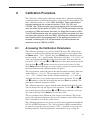
8 Calibration Procedure . . . . . . . . . . . . . . . . . . . . . . 35
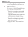
8.1 Accessing the Calibration Parameters. . . . . . . . . . . . . . . . 35
8.2 Calibration Procedure . . . . . . . . . . . . . . . . . . . . . . . . 36
9 Maintenance . . . . . . . . . . . . . . . . . . . . . . . . . . . 37
10 Troubleshooting. . . . . . . . . . . . . . . . . . . . . . . . . . 39
10.1 CE Comments . . . . . . . . . . . . . . . . . . . . . . . . . . . . 40
10.1.1 EMC Directive . . . . . . . . . . . . . . . . . . . . . . . . . . . . . . . . . 40
10.1.1.1 Immunity Testing . . . . . . . . . . . . . . . . . . . . . . . . . . . . . . . . . . . . 41
10.1.1.2 Emission Testing . . . . . . . . . . . . . . . . . . . . . . . . . . . . . . . . . . . . 41
10.1.2 Low Voltage Directive (Safety) . . . . . . . . . . . . . . . . . . . . . . . . . 41
ii

iii
Figures
Figure 1 Connecting a four-wire probe . . . . . . . . . . . . . . . . . . . . . . 12
Figure 2 1502A Front Panel . . . . . . . . . . . . . . . . . . . . . . . . . . . . 13
Figure 3 1502A Back Panel . . . . . . . . . . . . . . . . . . . . . . . . . . . . 14
Figure 4 Parameter Menu Structure . . . . . . . . . . . . . . . . . . . . . . . . 16
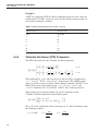
Figure 5 Serial Cable Wiring . . . . . . . . . . . . . . . . . . . . . . . . . . . 23

iv
Tables
Table1 International Electrical Symbols . . . . . . . . . . . . . . . . . . . . . 1
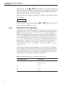
Table 2 Matching Certificate Values to 1502A ITS-90 Coefficients . . . . . . . 18
Table 3 Setting Coefficients Rtpw, a8, b8, a4, and b4 . . . . . . . . . . . . . . 19
Table 4 Setting Coefficients Rtpw, a5, and b5 . . . . . . . . . . . . . . . . . . 19
Table 5 Setting Coefficients R(273.16), a6, b6, c6, and d . . . . . . . . . . . . 20
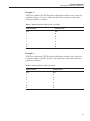
Table 6 Command List . . . . . . . . . . . . . . . . . . . . . . . . . . . . . . 27
Table 6 Command List Continued . . . . . . . . . . . . . . . . . . . . . . . . 28

1 Before You Start
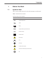
1.1 Symbols Used
Table 1 lists the symbols that may be used on the instrument or in this manual
and the meaning of each symbol.
Symbol Description
AC (Alternating Current)
AC-DC
Battery
Complies with European Union Directives
DC (Direct Current)
Double Insulated
Electric Shock
Fuse
PE Ground
Hot Surface (Burn Hazard)
Read the User’s Manual (Important Information)
Off
1
1 Before You Start
Symbols Used
Table1 International Electrical Symbols

Symbol Description
On
Canadian Standards Association
OVERVOLTAGE (Installation) CATEGORY II, Pollution Degree 2 per IEC1010-1 re
-
fers to the level of Impulse Withstand Voltage protection provided. Equipment of
OVERVOLTAGE CATEGORY II is energy-consuming equipment to be supplied from
the fixed installation. Examples include household, office, and laboratory appliances.
C-TIC Australian EMC mark
The European Waste Electrical and Electronic Equipment (WEEE) Directive
(2002/96/EC) mark.
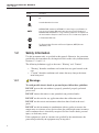
1.2 Safety Information
Use this instrument only as specified in this manual. Otherwise, the protection
provided by the instrument may be impaired. Refer to the safety information in
Sections 1.2.1 and 1.2.2.
The following definitions apply to the terms “Warning” and “Caution”.
• “Warning” identifies conditions and actions that may pose hazards to the
user.
• “Caution” identifies conditions and actions that may damage the instru-
ment being used.
1.2.1 Warnings
To avoid possible electric shock or personal injury, follow these guidelines.
DO NOT operate this unit without a properly grounded, properly polarized
power cord.
DO NOT connect this unit to a non-grounded, non-polarized outlet.
DO NOT use this unit for any application other than calibration work.
DO NOT use this unit in environments other than those listed in the user's
guide.
DO NOT use this instrument in combination with any probe to measure the
temperature or resistance of any device where the probe might come in contact
with a conductor that is electrically energized. Severe electric shock, personal
injury, or death may occur.
If this equipment is used in a manner not specified by the manufacturer, the
protection provided by the equipment may be impaired.
1502A Thermometer Readout
User’s Guide
2

Before initial use, or after transport, or after storage in humid or semi-humid
environments, or anytime the instrument has not been energized for more than
10 days, the instrument needs to be energized for a "dry-out" period of 2 hours
before it can be assumed to meet all of the safety requirements of the IEC
1010-1. If the product is wet or has been in a wet environment, take necessary
measures to remove moisture prior to applying power such as storage in a low
humidity temperature chamber operating at 50°C for 4 hours or more.
Follow all safety guidelines listed in this user's guide.
Calibration Equipment should only be used by Trained Personnel.
To avoid possible burn hazards, follow these guidelines.
This instrument can measure extreme temperatures. Precautions must be taken
to prevent personal injury or damage to objects. Probes may be extremely hot
or cold. Cautiously handle probes to prevent personal injury. Carefully place
probes on a heat/cold resistant surface or rack until they reach room
temperature.
1.2.2
Cautions
To avoid possible damage to the instrument, follow these guidelines.
DO NOT change the values of the calibration constants from the factory set
values unless you are recalibrating the instrument. The correct setting of these
parameters is important to the safety and proper operation of the instrument.
Allow sufficient air circulation by leaving at least 3 inches of space between the
thermometer and nearby objects.
For CE compliance and for performance, use only the AC adapter shipped with
the instrument. If the AC adapter needs to be replaced, contact an Authorized
Service Center.
This instrument and thermometer probes are sensitive and can be easily dam
-
aged. Always handle these devices with care. DO NOT allow them to be
dropped, struck, stressed, or overheated.
Probes are fragile instruments which can be damaged by mechanical shock,
over-heating, and absorption of moisture or fluids in the wires or hub. Damage
may not be visibly apparent but nevertheless can cause drift, instability, and
loss of accuracy. Observe the following precautions:
DO NOT allow probes to be dropped, struck, bent, or stressed.
DO NOT overheat probes beyond their recommended temperature range.
DO NOT allow any part of the probe other than the sheath to be immersed in
fluid.
DO NOT allow the probe hub or wires to be exposed to excessive
temperatures.
3
1 Before You Start
Safety Information

Keep the probe wires clean and away from fluids.
1.3 Authorized Service Centers
Please contact one of the following authorized Service Centers to coordinate
service on your Hart product:
Fluke Corporation, Hart Scientific Division
799 E. Utah Valley Drive
American Fork, UT 84003-9775
USA
Phone: +1.801.763.1600
Telefax: +1.801.763.1010
E-mail: [email protected]
Fluke Nederland B.V.
Customer Support Services
Science Park Eindhoven 5108
5692 EC Son
NETHERLANDS
Phone: +31-402-675300
Telefax: +31-402-675321
E-mail: [email protected]
Fluke Int'l Corporation
Service Center - Instrimpex
Room 2301 Sciteck Tower
22 Jianguomenwai Dajie
Chao Yang District
Beijing 100004, PRC
CHINA
Phone: +86-10-6-512-3436
Telefax: +86-10-6-512-3437
E-mail: [email protected]
1502A Thermometer Readout
User’s Guide
4

Fluke South East Asia Pte Ltd.
Fluke ASEAN Regional Office
Service Center
60 Alexandra Terrace #03-16
The Comtech (Lobby D)
118502
SINGAPORE
Phone: +65 6799-5588
Telefax: +65 6799-5588
E-mail: [email protected]
When contacting these Service Centers for support, please have the following
information available:
• Model Number
• Serial Number
• Voltage
• Complete description of the problem
5
1 Before You Start
Authorized Service Centers

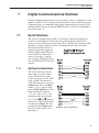
2 Introduction
The 1502A is a low-cost high-accuracy digital thermometer readout designed to
be used with 25Ω and 100Ω RTDs and SPRTs. Its unique combination of fea
-
tures makes it suitable for a wide variety of applications from laboratory mea
-
surement to industrial processes. Features of the 1502A include:
•
Measures 25Ω and 100Ω RTDs and SPRTs
•
Four-wire connection eliminates lead resistance effects
•
Accuracy: 0.006°C at 0°C
•
Resolution: 0.001°C
•
Fast one-second measurement cycle
•
Adjustable digital filter
•
Accepts ITS-90 characterization coefficients
•
Also accepts Callendar-Van Dusen and IPTS-68 coefficients
• Adjustable excitation current
• Displays temperature in Celsius, Fahrenheit, or Kelvin or displays resis-
tance in ohms
• Password protection of critical parameters
• Large, bright eight-digit LED display
• Serial RS-232 interface standard; IEEE-488 GPIB interface optional
• Detachable power cord
• Light weight, small and portable
•
Sturdy, reliable construction
7
2 Introduction

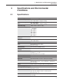
3 Specifications and Environmental
Conditions
3.1 Specifications
Resistance Range
0
Ω
to 400
Ω
, auto-ranging
Resistance Accuracy, one year
1
0
Ω
to 20
Ω
: 0.0005
Ω
20
Ω
to 400
Ω
: 0.0025% (25 ppm) of reading
Resistance Accuracy, short
term
1, 2
0
Ω
to 30
Ω
: 0.0005
Ω
30
Ω
to 400
Ω
: 0.0015% (15 ppm) of reading
Temperature Range
3
–200°C to 962°C (–328°F to 1764°F)
Temperature Accuracy
1, 3, 4
–100°C: 0.004°C
0°C: 0.006°C
100°C: 0.009°C
200°C: 0.012°C
300°C: 0.015°C
400°C: 0.018°C
500°C: 0.021°C
600°C: 0.024°C
Temperature Coefficient of
Resistance
1
1 ppm/°C
Resistance Resolution
0
Ω
to 20
Ω
: 0.0001
Ω
20
Ω
to 400
Ω
: 0.001
Ω
Temperature Resolution
0.001°C
Probe
Nominal R(0.01°C): 25
Ω
to 100
Ω
RTD, PRT, or SPRT
Probe Connection
4-wire with shield, 5-pin DIN connector
Maximum acceptable lead
resistance
100
Ω
Probe Characterizations
ITS-90 sub-ranges 4, 6, 7, 8, 9, 10, and 11
IPTS-68: R
0
,
α
,
δ
,a
4
, and c
4
Callendar-Van Dusen: R
0
,
α, δ
, and
β
Probe Excitation Current
0.5 and 1 mA , user selectable, 2Hz
Measurement Period
1 second
Digital Filter
Exponential, 0 to 60 seconds time constant (user-selectable)
Communications
RS-232 serial standard
IEEE-488 (GPIB) optional, conforms to IEEE-488.1, capability AH1,
SH1, T6, L4, DC1
Display
8-digit, 7-segment, yellow-green LED; 0.5 inch high characters
Clock accuracy, typical
0.01%
Operating Temperature Range
Full accuracy: 16°C to 30°C
Absolute: 0°C to 55°C
AC power
115 VAC ±10%, 50/60 Hz, 10 W, nominal, 1 A maximum
230 VAC ±10%, 50/60 Hz, 10 W, 1 A, nominal (optional)
Detachable power cord
Size
5.6 inches (14.3 cm) wide x 7.1 inches (18.1 cm) deep x 2.4 inches
(6.1 cm) high
9
3 Specifications and Environmental Conditions
Specifications

Weight
2.2 lb. (1.0 kg)
Safety
OVERVOLTAGE (Installation) CATEGORY II, Pollution Degree 2 per
IEC 1010-1
1
Accuracy specifications apply within the recommended operating temperature range. Accuracy limits are
increased by a factor of the temperature coefficient outside this range.
2
Short-term accuracy includes nonlinearity and noise uncertainties. It does not include drift or calibration
uncertainties.
3
The temperature range may be limited by the sensor.
4
Temperature accuracy is for the 1502A only. It does not include probe uncertainty or probe characteriza
-
tion errors.
3.2 Environmental Conditions
Although the instrument has been designed for optimum durability and trou
-
ble-free operation, it must be handled with care. The instrument should not be
operated in an excessively dusty or dirty environment. Maintenance and clean
-
ing recommendations can be found in the Maintenance Section of this manual.
The instrument operates safely under the following conditions:
• Ambient temperature range: Absolute 0–55°C (32–131°F); [full accuracy
16–30°C (61–86°F)]
• Ambient relative humidity: maximum 80% for temperature < 31°C, de-
creasing linearly to 50% at 40°C
• Pressure: 75kPa–106kPa
• Mains voltage within ±10% of nominal
• Vibrations should be minimized
•
Altitude less than 2,000 meters
•
Indoor use only
1502A Thermometer Readout
User’s Guide
10

4 Quick Start
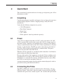
This section briefly explains the basics of setting up and operating your 1502A
thermometer readout.
4.1 Unpacking
Unpack the thermometer carefully and inspect it for any damage that may have
occurred during shipment. If there is shipping damage, notify the carrier
immediately.
Verify that the following components are present:
•
1502A Thermometer
•
Extra Probe Connector
•
Power Cord
• User’s Guide
• Probe (optional—must be purchased separately)
4.2 Power
Your 1502A is configured for either 115 VAC (±10%) operation or 230 VAC
(±10%) operation. Be careful to only connect the 1502A to a mains supply of
the correct voltage. Otherwise, the instrument may be damaged. The required
voltage is indicated on the back of the 1502A. Power requirements are listed in
Section 3.1, Specifications. The IEC type power cord connects to the back of
the 1502A. The cord must be plugged in to a grounded outlet. The power
switch is located at the back of the 1502A.
When the 1502A is powered on, wait briefly while it initializes. It will then be
-
gin measuring and displaying temperature.
Because of the quality of the components used in the 1502A, it exhibits nearly
negligible drift as it warms up. The warm-up drift is typically less than 5 ppm.
Nevertheless, to ensure the best accuracy and stability, you may want to allow
the 1502A to warm up for ten minutes before use.
Accurate measurement requires that the probe be connected properly to the in
-
put and the correct probe characterization set.
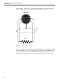
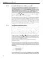
4.3 Connecting the Probe
The RTD or SPRT probe connects to the back of the 1502A using a five-pin
DIN plug. Figure 1 shows how a four-wire probe is wired to the five-pin DIN
connector. One pair of wires attaches to pins 1 and 2 and the other pair attaches
11
4 Quick Start
Unpacking

to pins 4 and 5. (Pins 1 and 5 source current and pins 2 and 4 sense the poten
-
tial.) If a shield wire is present it should be connected to pin 3.
A two-wire probe can also be used with the 1502A. It is connected by attaching
one wire to both pins 1 and 2 of the plug and the other wire to both pins 4 and
5. If a shield wire is present it should be connected to pin 3. Accuracy may be
significantly degraded using a two-wire connection because of lead resistance.
1502A Thermometer Readout
User’s Guide
12
1
2
4
5
RTD Sensor
Probe Connector
3
Shield
Figure 1 Connecting a four-wire probe

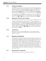
5 Parts and Controls
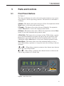
5.1 Front Panel Buttons
See Figure 2.
The front panel buttons are used to select units of measurement, access operat
-
ing parameters, and alter operating parameters. The function of each button is
as follows:
C/Probe—This button selects units of degrees Celsius. In conjunction with the
Menu button, it selects the probe parameter menu.
F/Sample—This button selects units of degrees Fahrenheit. In conjunction
with the Menu button, it selects the sample parameter menu.
K/Comm—This button selects units of Kelvin. In conjunction with the Menu
button, it selects the communication parameter menu.
Ω/Exit (Cal)—This button selects resistance in ohms. While editing a parame-
ter, it cancels the immediate operation and skips to the next parameter. If the
Exit button is pressed for more than one-half second the menu is exited. In
conjunction with the Menu button, it selects the calibration parameter menu.
Menu/Enter—This button allows one of the unit/menu buttons to select a
menu. When editing a parameter, it accepts the new value and skips to the next
operation.
L and R —When editing a numeric parameter, these buttons move between
digits. The selected digit flashes.
U and D— When editing a parameter, these buttons increase or decrease the
value of the parameter or a selected digit.
13
5 Parts and Controls
Front Panel Buttons
C
PROBE
F
COMM
K
SAMPLE
W
EXIT
MENU
ENTER
1502A
THERMOMETER
READOUT
84.981 C
Figure 2 1502A Front Panel

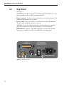
5.2 Rear Panel
See Figure 3.
Serial Port - The DB-9 connector is for interfacing the thermometer to a com
-
puter or terminal with serial RS-232 communications.
Probe Connector - At the rear of the thermometer is the probe connector. The
probe must be connected for operation.
Power Switch - The power switch is located on the rear of the thermometer.
The AC power switch turns the unit on and off.
AC Power - At the rear of the instrument is the removable power cord that
plugs into a standard 115 VAC grounded socket. (230 VAC optional)
IEEE-488 Port (optional) - The GPIB connector is for interfacing the ther
-
mometer to a computer or terminal with IEEE-488 communications.
1502A Thermometer Readout
User’s Guide
14
RS-232
IEEE-488
PROBE
POWER
l
201811
FLUKE CORPORATION
HART SCIENTIFIC DIVISION
www.hartscientific.com
115 VAC 50/60 Hz 10 W
NO USER SERVICABLE PARTS
Figure 3 1502A Back Panel

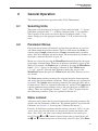
6 General Operation
This section explains basic operation of the 1502A Thermometer.
6.1 Selecting Units
Temperature can be displayed in degrees Celsius (indicated with “C”), degrees
Fahrenheit (indicated with “F”), or Kelvin (indicated with “A” for absolute).
The resistance of the sensor can also be displayed (indicated with “o”for
ohms). Simply press the appropriate unit button, C, F, K, or Ω to select the
units.
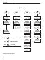
6.2 Parameter Menus
Except for unit selection, all functions and operating parameters are accessed
and edited within the parameter menus. There are four menus: the Probe pa
-
rameter menu, Sample parameter menu, Comm (communication) parameter
menu, and Cal (calibration) parameter menu. The arrangement of parameters in
the menus is shown in Figure 4 on page 16.
Menus are selected by pressing the Menu/Enter button followed by the appro-
priate menu selection button. The name of the menu will briefly appear on the
display. For example, the Probe menu is selected by pressing the Menu/Enter
button (“SEt?” appears on the display) followed by the C/Probe button
(“ProbE” appears). Selecting the Cal menu requires that you press the
Menu/Enter button then press the Ω/Exit button and hold it down for at least
one second.
The Probe menu contains parameters for selecting the probe characterization
and setting the characterization coefficients. These parameters are explained in
Section6.4.TheSample menu contains parameters for setting the filter and ex
-
citation current. These are explained in Sections 6.5 and 6.6. The Comm menu
contains communication parameters such as the serial baud rate or IEEE-488
address. These are explained in Sections 7.1 and 7.2. The Cal menu contains
the calibration parameters. These are explained in Section 8.1.
6.3 Menu Lockout
All menus can be locked out to prevent inadvertently changing parameters. By
default, only the Cal menu is locked out. The lockout option is accessed in the
Cal menu (see Section 8.1 “Accessing the Calibration Parameters”).
If menus are locked out you must enter the correct password (“2051”) to gain
access. After you select the menu (see the previous section) the display will
show “PA= 0000” and allow you to change the number to the correct pass
-
word. Use the L and R buttons to move between the password digits and
the U and D buttons to increase or decrease the value of a digit. Press Enter
15
6 General Operation
Selecting Units

1502A Thermometer Readout
User’s Guide
16
Menu
Sample Comm (Cal)Probe
Set clockSet filterSet probe type Enter password
Set time stampSet currentSet coefficients Set menu lockout
Set baud rateSet power saver Set CAL0
Set sample periodTest conversion Set CAL 100
Set duplex Set CAL 400
Set linefeed Factory reset
Set GPIB address
Set GPIB EOS
11.23.30FI= 4Pr= t90 PA= 0000
ts= OFFCur= 1.0 LO=CaL
2400 bPS= OFF -0.0006
00.00.01100.0000 +0.0128
duP=FULL -0.0011
LF= ON rESEt?
Add= 22
E= LF
Press after changing a parameter
Press briefly to skip a parameter
Hold to exit the menu
Enter
Exit
Exit
Figure 4 Parameter Menu Structure
Page is loading ...
Page is loading ...
Page is loading ...
Page is loading ...
Page is loading ...
Page is loading ...
Page is loading ...
Page is loading ...
Page is loading ...
Page is loading ...
Page is loading ...
Page is loading ...
Page is loading ...
Page is loading ...
Page is loading ...
Page is loading ...
Page is loading ...
Page is loading ...
Page is loading ...
Page is loading ...
Page is loading ...
Page is loading ...
Page is loading ...
-
 1
1
-
 2
2
-
 3
3
-
 4
4
-
 5
5
-
 6
6
-
 7
7
-
 8
8
-
 9
9
-
 10
10
-
 11
11
-
 12
12
-
 13
13
-
 14
14
-
 15
15
-
 16
16
-
 17
17
-
 18
18
-
 19
19
-
 20
20
-
 21
21
-
 22
22
-
 23
23
-
 24
24
-
 25
25
-
 26
26
-
 27
27
-
 28
28
-
 29
29
-
 30
30
-
 31
31
-
 32
32
-
 33
33
-
 34
34
-
 35
35
-
 36
36
-
 37
37
-
 38
38
-
 39
39
-
 40
40
-
 41
41
-
 42
42
-
 43
43


Ask a question and I''ll find the answer in the document
Finding information in a document is now easier with AI
Related papers
-
Fluke Calibration 1504 User manual
-
Fluke FL700-154 Quick start guide
-
-
-
-
-
Fluke Calibration 1521 User manual
-
-
-
Other documents
-
 Zoo Med TH-31 User guide
-
Black Box Dual-Input Thermometer User manual
-
-
Harbor Freight Tools Instant Read Digital Thermometer User manual
-
-
Omega DP9601 Owner's manual
-
Omega Engineering DP95 User manual
-
-
-
Alpha 178 Installation guide
