
MXS
ODO
DST
TM
AVS
L
OPERATING INSTRUCTIONS
AUTO (AUTOMATIC START/STOP) FUNCTION
AUTO
DST
When main unit is left without receiving any signal for 60-70 minutes
continuously, power supply is shut down and main unit will display (
) only
as the figure. By pressing M button or S/S button, or by receiving signal, this
function is released.
POWER SAVING FUNCTION
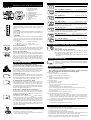
TROUBLE SHOOTING
• The following situations do not indicate malfunction of the cyclocomputer. Check
the following before taking to repair.
* When current speed does not appear, short-circuit the contact on the back with
metal. The unit will function normally if the speed display appears.
Display response is slow.
-----Is it at a low temperature under 32°F(0°C)?
-----It returns to normal state when temperature rises.
No display.
-----Has the Lithium Battery in the main unit worn out?
-----Replace the Lithium Battery with a new one.
Incorrect data appear.
-----Execute "All Clear" operation.
Current speed does not appear.
-----Is there anything on the contact of the main unit or of the bracket?
-----Wipe the contact clean.
-----Is the distance between sensor and magnet too far?
-----Are the marking line of the sensor and the center of magnet matched each other?
-----Refer to "Sensor/Magnet Mounting" and re-adjust correctly.
-----Is the wire broken?
-----Replace the Bracket & Sensor part with a new one.
Transmission signal loss in damp or wet conditions.
-----Water or condensation may collect between the bracket sensor and the computer
causing an interruption in the data transmission. Wipe the contacts with dry cloth.
Contacts can also be treated with a water repellent silicon jell from an automotive parts
or hardware store. Do not use industrial water repellent; it may damage the bracket.
When the S/S button is pressed, the unit doesn't activate or stop.
-----Is the unit in the Auto function?
-----The S/S button doesn't function in the Auto function.
MAINTENANCE/PRECAUTIONS
• Do not leave the main unit exposed to direct sunlight when the unit is not in use.
• Do not disassemble the main unit, sensor and magnet.
• Don't pay too much attention to your computer's functions while riding! Keep your eyes on
the road and duly consider to traffic safety.
• Check relative position of sensor and magnet periodically.
• For cleaning, use neutral detergent on soft cloth, and wipe off later with dry cloth. Do not
apply paint thinner, benzine, or alcohol, to avoid damages on the surface.
• If there is mud, sand or the like clogs between the button and the body, the movement of
the button may be disturbed. Softly wash away such objects with water.
SPD Current Speed
0.0(3.0) - 65 mile/h(27inch) ±1 mile/h under31 miles/h
This is always displayed on the main display and updated once a second.
ODO Total Distance (Odometer) 0.0 - 9999.9 mile ±0.1 mile
This is continuously measured until battery wears down or all clear opera-
tion is done. At 10,000 miles(km), it returns to zero and counting begins
anew.
DST Trip Distance 0.00 - 999.99 mile ±0.01 mile
The trip distance from start to current point is displayed. With Reset opera-
tion, it returns to zero.
TM Elapsed Time 0:00'00" - 9:59'59" ±0.003 %
Elapsed time is measured from start to current point, in units of hours, min-
utes and seconds. At 10 hours, it returns to zero and counting begins anew.
With Reset operation, it returns to zero.
AVS Average Speed 0.0 - 65.0mile/h ±0.3 mile/h
The average speed from start to current point is displayed within 27 hours
46 minutes 39 seconds (99,999 seconds) or 999.99 miles (km). If either is
exceeded, (.E) is displayed and calculation ceases.
MXS Maximum Speed 0.0(3.0) - 65 mile/h(27inch) ±1 mile/h
With Reset operation, it returns to zero and counting begins anew.
12-hour clock time 0:00' - 11:59' ±0.003 %
The current time is displayed by a 12-hour clock.
This function switches the main unit to start or stop automatically, in which
AUTO symbol appears on the screen, and you are free from pressing S/S
button each time.
How to switch on/off the Auto Function.
In TM, DST or AVS, this function switches on/off with each press of SET
button. When on, AUTO symbol appears. *With this function, it ceases
measuring elapsed time during a stop.
* 2 seconds may be elapsed if mount the main unit to the bracket with this
function on.
Fig.4
MEASURING AND DISPLAY FUNCTIONS
Fig.5
Fig.6
Fig.7
Fig.2
Fig.3
Fig.1
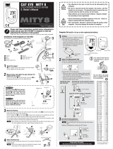
BUTTON FUNCTION
• M button (Fig.1)
Changes the display in the order shown in fig. 1, and data is
displayed on the sub-display. *If held over 2 seconds, 12-hour clock
appears.
• S/S button
Starts and stops the measurement of trip distance and elapsed time.
During operation, speed scale symbol flashes. In Auto Function, this
button is invalid.
• SET Button
This is for setting the wheel circumference and clock time, switching
on/off Auto Function and to clear all present data and any
irregularity. When pressed in stop state in each mode, the following
can be revised.
• In ODO mode ------------------ Wheel circumference
• In
mode -------------------- 12-hour clock
• In TM, DST or AVS mode --- On/off the Auto function
Reset Operation: (Fig.2)
Select any mode except ODO, then press M button and S/S button
simultaneously. MXS, AVS, DST and TM will become zero. (When
done in ODO, registered wheel circumference will be displayed.)
All Clear Operation: (Fig.3)
When M button, S/S and set buttons are pressed simultaneously, all
data stored (ODO, speed scale, Wheel circumference and clock
time) is erased. All displays illuminate, then mile/h symbol
illuminates. This should only be executed after replacing battery or
when irregular display occurs due to static electricity, etc. Since all
memories are erased, set necessary data again according to "Main
Unit Preparation".
MAIN UNIT PREPARATION
The following must be completed before operating.
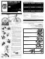
(1) How to measure wheel circumference (L) of your bike (Fig.4)
Put a mark on the tire tread and ride the bike one full wheel revolu-
tion. Mark the start and the end of the revolution on the ground and
then measure the distance between the two marks. This is your ac-
tual circumference. Or, the "Setting Values Cross Reference Table"
tells you an approximate circumference according to tire size.
(2) Setting Speed Scale
Preform all clear operation. All displays will illuminate. Then mile/h
alone will be displayed as illustrated in fig.5. Km/h and mile/h are
alternately displayed with each press of S/S button. Press M button
to set desired speed scale. The display will change as fig. 6.
(3) Setting the wheel circumference (Fig.6)
The standard wheel circumference of 216 cm for 27" wheel is dis-
played. When using 216 cm without revision, press M button. ODO
will be displayed and 216 cm is set. For revision, press S/S button to
increase the number by one. To increase rapidly, hold down the but-
ton. When the desired number appears, press M button. ODO will be
displayed, and the desired number is set.
(4) Resetting or changing the wheel circumference
Set main unit in ODO with M button, and stop it with S/S button.
Press SET button. The stored number will flicker on the sub-display.
Revise the number as desired according to the instructions in (3).
Setting the clock time (Fig.7)
Press M button over 2 seconds to select
, and stop it with S/S
button. Then press SET button, and minutes flash. Press S/S button
to advance minutes by one. To advance rapidly, hold down the but-
ton. Set the time one or two minutes ahead of the current time. Then
press M button, and hours will flash. Use S/S button the same way.
Press SET button to complete time setting. *When you press the
SET button, the undisplayed seconds will turn to zero. For accuracy,
set by the radio time signal.
HOW TO REPLACE THE BATTERY
Turn main unit over, remove battery case cover with coin and insert
a new lithium battery properly (CR1620 or CR1616) with the (+) pole
upward (fig.8), and close the cover securely.
* Please make sure to do the All Clear operation after replacing
battery, and to set the unit again.
Reset Operation
All Clear Operation
A. Main Display (Speed)
B. Sensor Pulse Symbol
C. Mode Symbol
D. Speed Scale Symbol
E. Auto Mode Symbol
F. Sub-Display (Selected Function)
G. M (Mode) Button
H. S/S (Start/Stop) Button
I. Set Button
J. Battery Case Cover
K. Contact
DST
ODO
DST
TM
AVS
MXS
close
open
Fig.8
TOMO XC


 1
1
 2
2


![CAT EYEEnduro 8 [CC-ED300]](//vs1.manuzoid.com/store/data/000426304_2-f43a957600499ff339090d0d3770f813-160x210.png) CAT EYE Enduro 8 [CC-ED300] User manual
CAT EYE Enduro 8 [CC-ED300] User manual
 cat-eye CC-MT400 Mity 8 User manual
Cateye Enduro 2 [CC-ED200] User manual
Cateye CC-RD100N Owner's manual
![CAT EYEEnduro 8 [CC-ED300]](http://vs1.manuzoid.com/store/data/000426304_2-f43a957600499ff339090d0d3770f813-160x210.png)

PYLE Audio PBKCM4WL User manual
Trek Sensor 2.0 User manual
Kyosho VZW408 User manual
Knog Nerd 5 Owner's manual
Shimano FlightDeck SC-6502 Specification
Shimano SC-6501 Service Instructions
Bell F20 User manual