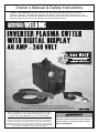
Harbor Freight Tools 240 Volt Inverter Plasma Cutter with Digital Display Owner's manual
- Category
- Welding System
- Type
- Owner's manual
This manual is also suitable for

Visit our website at: http://www.harborfreight.com
Email our technical support at: [email protected]
14e
Owner’s Manual & Safety Instructions
Save This Manual Keep this manual for the safety warnings and precautions, assembly,
operating, inspection, maintenance and cleaning procedures� Write the product’s serial number in the
back of the manual near the assembly diagram (or month and year of purchase if product has no number)�
Keep this manual and the receipt in a safe and dry place for future reference�
When unpacking, make sure that the product is intact
and undamaged� If any parts are missing or broken,
please call 1‑888‑866‑5797 as soon as possible�
Copyright
©
2014 by Harbor Freight Tools
®
� All rights reserved�
No portion of this manual or any artwork contained herein may be reproduced in
any shape or form without the express written consent of Harbor Freight Tools�
Diagrams within this manual may not be drawn proportionally� Due to continuing
improvements, actual product may differ slightly from the product described herein�
Tools required for assembly and service may not be included�
Read this material before using this product.
Failure to do so can result in serious injury.
SAVE THIS MANUAL.

Page 2 For technical questions, please call 1-888-866-5797. ITEM 62204
SAFETY OPERATION MAINTENANCESETUP
Table of Contents
Safety ��������������������������������������������������������� 2
Specifications ��������������������������������������������� 5
Setup ���������������������������������������������������������� 6
Operation ���������������������������������������������������� 8
Maintenance ���������������������������������������������� 12
Troubleshooting ����������������������������������������� 13
Circuit Diagram ������������������������������������������ 17
Parts List and Diagram ������������������������������ 22
Warranty ���������������������������������������������������� 24
WARNING SYMBOLS AND DEFINITIONS
This is the safety alert symbol� It is used to alert you to potential
personal injury hazards� Obey all safety messages that
follow this symbol to avoid possible injury or death�
Indicates a hazardous situation which, if not avoided,
will result in death or serious injury�
Indicates a hazardous situation which, if not avoided,
could result in death or serious injury�
Indicates a hazardous situation which, if not avoided,
could result in minor or moderate injury�
Addresses practices not related to personal injury�
IMPORTANT SAFETY INSTRUCTIONS
Read all safety warnings and instructions.
Failure to follow the warnings and instructions may result in electric shock, fire and/or serious injury.
Save all warnings and instructions for future reference.
1� DANGER! People with pacemakers should
not use this Plasma Cutter or be nearby
during use. Plasma Cutters, such as this one,
produce strong, fluctuating electromagnetic
fields that can cause pacemaker interference
or pacemaker failure. People with pacemakers
should consult their physician(s) for advice.
2� Maintain a safe working environment.
Keep the work area well lit� Make sure
there is adequate surrounding workspace�
Keep the work area free of obstructions, grease,
oil, trash, and other debris� Do not use in areas
near flammable chemicals, dusts, and vapors�
Do not use in a damp or wet location�
3� Never leave the Plasma Cutter unattended
when it is plugged into an electrical outlet.
Turn off the Plasma Cutter, and unplug it from its
electrical outlet before leaving�
Unplug the Plasma Cutter from its electrical
outlet before performing any inspection,
maintenance, or cleaning procedures,
including changing accessories.
4� Avoid unintentional starting. Make sure
switch is in off position before plugging in�
Make sure you are prepared to begin work
before turning on the Plasma Cutter�
5� Prevent eye injury and burns. Wearing personal
protective equipment reduces the risk of injury�
• Wear an ANSI‑approved welding helmet
featuring at least a number 10 shade lens rating�
• Leather leggings, fire resistant shoes or
boots should be worn when using this
product� Do not wear pants with cuffs, shirts
with open pockets, or any clothing that can
catch and hold molten metal or sparks�
• Keep clothing free of grease, oil, solvents,
or any flammable substances� Wear dry,
insulating gloves and protective clothing�
• Wear an approved head covering to protect
the head and neck� Use aprons, cape, sleeves,
shoulder covers, and bibs designed and
approved for welding and cutting procedures�
• When welding/cutting overhead or in
confined spaces, wear fi resistant ear plugs
or ear muffs to keep sparks out of ears�

Page 3For technical questions, please call 1-888-866-5797.ITEM 62204
SAFETYOPERATIONMAINTENANCE SETUP
6� Maintain labels and nameplates
on the Plasma Cutter.
These carry important information�
If unreadable or missing, contact
Harbor Freight Tools for a replacement�
7� Prevent accidental fires. Remove any
combustible material from the work area�
• When possible, move the work to a location well
away from combustible materials� If relocation
is not possible, protect the combustibles with
a cover made of fire resistant material�
• Remove or make safe all combustible
materials for a radius of 35 feet (10 meters)
around the work area� Use a fire resistant
material to cover or block all open doorways,
windows, cracks, and other openings�
• Enclose the work area with portable fire
resistant screens� Protect combustible
walls, ceilings, floors, etc�, from sparks
and heat with fire resistant material�
• If working on a metal wall, ceiling, etc�,
prevent ignition of combustibles on the other
side by moving the combustibles to a safe
location� If relocation of combustibles is not
possible, designate someone to serve as a
fire watch, equipped with a fire extinguisher,
during the cutting process and for at least
one half hour after the cutting is completed�
• Do not weld or cut on materials having a
combustible coating or combustible internal
structure, as in walls or ceilings, without an
approved method for eliminating the hazard�
• Do not dispose of hot slag in containers
holding combustible materials� Keep a fire
extinguisher nearby and know how to use it�
• After welding or cutting, make a thorough
examination for evidence of fire� Be aware
that easily visible smoke or flame may not
be present for some time after the fire has
started� Do not weld or cut in atmospheres
containing dangerously reactive or flammable
gases, vapors, liquids, and dust�
• Provide adequate ventilation in work areas
to prevent accumulation of flammable gases,
vapors, and dust� Do not apply heat to a
container that has held an unknown substance
or a combustible material whose contents, when
heated, can produce flammable or explosive
vapors� Clean and purge containers before
applying heat� Vent closed containers, including
castings, before preheating, welding, or cutting�
• Only use compressed air or nitrogen to
operate the Plasma Cutter� Never use
other compressed gases� Don’t exceed
maximum PSI for this product as stated on
the specification table on page page 5�
8� INHALATION HAZARD:
Welding and Cutting Produce
TOXIC FUMES.
Exposure to welding or cutting
exhaust fumes can increase
the risk of developing certain cancers,
such as cancer of the larynx and lung cancer�
Also, some diseases that may be linked to
exposure to welding or cutting exhaust fumes are:
• Early onset of Parkinson’s Disease
• Heart disease • Ulcers
• Damage to the reproductive organs
• Inflammation of the small intestine or stomach
• Kidney damage
• Respiratory diseases such as
emphysema, bronchitis, or pneumonia
Use natural or forced air ventilation
and wear a respirator approved by
NIOSH to protect against the fumes
produced to reduce the risk of
developing the above illnesses�
9� Avoid overexposure to fumes and gases.
Always keep your head out of the fumes�
Do not breathe the fumes� Use enough ventilation
or exhaust, or both, to keep fumes and gases
from your breathing zone and general area�
• Where ventilation is questionable, have a
qualified technician take an air sampling to
determine the need for corrective measures�
Use mechanical ventilation to improve
air quality� If engineering controls are not
feasible, use an approved respirator�
• Work in a confined area only if it
is well ventilated, or while wearing
an air‑supplied respirator�
• Follow OSHA guidelines for
Permissible Exposure Limits (PELs)
for various fumes and gases�
• Follow the American Conference
of Governmental Industrial
Hygienists recommendations for
Threshold Limit Values (TLVs)
for fumes and gases�
• Have a recognized specialist in Industrial
Hygiene or Environmental Services
check the operation and air quality
and make recommendations for the
specific welding or cutting situation�
10� Keep hoses away from welding/cutting area.
Examine all hoses and cables for cuts,
burns, or worn areas before each use�
If any damaged areas are found, replace
the hoses or cables immediately�

Page 4 For technical questions, please call 1-888-866-5797. ITEM 62204
SAFETY OPERATION MAINTENANCESETUP
11� Proper cylinder care. Secure cylinders to a
cart, wall, or post, to prevent them from falling�
All cylinders should be used and stored in an
upright position� Never drop or strike a cylinder�
Do not use cylinders that have been dented�
Cylinder caps should be used when moving or
storing cylinders� Empty cylinders should be kept
in specified areas and clearly marked “empty�”
12� Never use oil or grease on any inlet connector,
outlet connector, or cylinder valves.
13� Use only supplied Torch on this Plasma Cutter.
Using components from other systems may cause
personal injury and damage components within�
14� WARNING: This product, when used for welding,
plasma cutting, soldering, or similar applications,
produces chemicals known to the State of
California to cause cancer and birth defects
or other reproductive harm� (California Health
& Safety Code § 25249�5, et seq.)
15� USE PROPER EXTENSION CORD. Make sure
your extension cord is in good condition� When
using an extension cord, be sure to use one heavy
enough to carry the current your product will draw�
An undersized cord will cause a drop in line
voltage resulting in loss of power and overheating�
A 50 foot extension cord must be at least
12 gauge in diameter, and an 100 foot extension
cord must be at least 10 gauge in diameter�
If in doubt, use the next heavier gauge� The
smaller the gauge number, the heavier the cord�
16� KEEP CHILDREN AWAY� All visitors should
be kept safe distance from work area�
17� MAKE WORKSHOP KID PROOF with padlocks,
master switches, or by removing starter keys�
18� USE RIGHT Plasma Cutter� Don’t force
Plasma Cutter or attachment to do a
job for which it was not designed�
19� SECURE WORK� Use clamps or a vise to hold
work� It’s safer than using your hand and it
frees both hands to operate Plasma Cutter�
20� MAINTAIN PLASMA CUTTER WITH CARE�
Keep Plasma Cutter clean for best and
safest performance�
Follow instructions for changing accessories�
21� Inspect before every use;
do not use if parts loose or damaged�
22� WARNING: The brass components of this product
contain lead, a chemical known to the State
of California to cause cancer and birth defects
or other reproductive harm� (California Health
& Safety Code § 25249�5, et seq.)
23� WARNING: The cord of this product
contains lead, a chemical known to the
State of California to cause cancer, and birth
defects or other reproductive harm� Wash
hands after handling� (California Health
& Safety Code § 25249�5, et seq.)
Symbology
Canadian Standards Association
Underwriters Laboratories, Inc�
VAC
Volts Alternating Current
A
Amperes

Page 5For technical questions, please call 1-888-866-5797.ITEM 62204
SAFETYOPERATIONMAINTENANCE SETUP
Specifications
Rated Input 240VAC / 50/60Hz / 30A
Open Circuit Voltage (OCV) 360V
Cutting Current 15 ‑ 40A DC
Rated Output Voltage 96VDC
Rated Duty Cycle
60%
100%
@
@
40A
30A
Maximum Cutting Thickness
3/8" Mild Steel @ 10 IPM (Rated)
5/8" Mild Steel @ 5 IPM (Severence)
1/4" Stainless Steel, Aluminum, Galvanized Steel
1/8" Brass, Copper
Arc Striking System 2�5 second pilot arc
Gas Supply Clean, dry, oil‑free air, or nitrogen gas
Air Outlet Pressure ‑ Compressor 90 ‑ 120 PSI
Working Pressure ‑ Plasma Cutter 60 ‑ 80 PSI
Air Consumption
3�6 CFM @ 60 PSI
4�5 CFM @ 80 PSI
Air Inlet 1/4″ - 18 NPT

Page 6 For technical questions, please call 1-888-866-5797. ITEM 62204
SAFETY OPERATION MAINTENANCESETUP
Setup
Read the ENTIRE IMPORTANT SAFETY INFORMATION section at the beginning of this
manual including all text under subheadings therein before set up or use of this product.
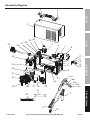
Note: For additional information regarding the parts listed in the following pages,
refer to the Assembly Diagram near the end of this manual�
Note: This Plasma Cutter may be shipped with a protective plug
covering the Air Inlet� Remove this plug before set up�
Power Plug
1� A 6‑50P plug is wired into this item,
rated to 250VAC and 50A�
2� If the receptacle does not match the plug,
make sure that it is a 230-250VAC receptacle
rated to at least 30 amps.
If the receptacle is rated properly, a qualified
electrician can cut the plug off of this machine
and install a different appropriate 250VAC plug�
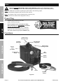
Functions
Air Pressure
Regulator
Power Cord
Storage Hook
Power Cord
Storage Hook
Torch
Ground
Clamp
Air Pressure
Gauge
Power
Cord
(on back)
Air Inlet
(on back)
Power
Switch
Air
Switch
Figure A

Page 7For technical questions, please call 1-888-866-5797.ITEM 62204
SAFETYOPERATIONMAINTENANCE SETUP
Air Supply
TO PREVENT SERIOUS INJURY AND DEATH FROM EXPLOSION:
Use only clean, dry, regulated, oil-free, compressed air or nitrogen gas with this Plasma Cutter.
Do not use oxygen, acetylene, carbon dioxide, combustible gases,
or any other bottled gas as a power source for this Plasma Cutter.
1� Use a compressor that is capable of
supplying 4�5 CFM @ 80 PSI�
2� Incorporate a filter, regulator with pressure gauge,
dryer, in‑line shutoff valve, and quick coupler for
best service� An in-line shutoff ball valve is an
important safety device because it controls
the air supply even if the air hose is ruptured.
The shutoff valve should be a ball valve
because it can be closed quickly.
Note: In humid locations, multiple dryers may need
to be incorporated to keep the air dry. MOISTURE
IN AIR SUPPLY MAY CAUSE SHORTENED
COMPONENT LIFE AND POOR CUT QUALITY.
Note: Do not use an oiler system with this
Plasma Cutter. The oil will mix with the air
being propelled, causing poor results.
3� Attach an air hose to the compressor’s air outlet�
Connect the air hose to the Air Inlet on the back
of the Plasma Cutter� Other components, such
as a coupler plug and quick coupler, will make
operation more efficient, but are not required�
Note: Air flow, and therefore Plasma Cutter
performance, can be hindered by undersized air
supply components�
The air hose must be long enough to reach
the work area with enough extra length to
allow free movement while working�
Setting Compressor's Air Pressure
1� Set the Plasma Cutter’s Power
Switch to the OFF position�
2� Turn on the air compressor according to
the manufacturer’s directions and allow it
to build up pressure until it cycles off�
3� Set the air compressor’s output air
pressure regulator between 90 - 120
PSI� Adjust the pressure gradually, while
observing the air pressure gauge�
4� Inspect the air connections for leaks�
Repair any leaks found�
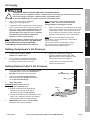
Setting Plasma Cutter's Air Pressure
1� Plug in the Plasm Cutter, set the Power Switch
to the ON position and set the Air Switch to
SET AIR� There will be constant air flow�
2� Pull up on the Air Pressure Regulator
and set between 60 - 80 PSI, as observed
on the Air Pressure Gauge.
3� TEST AIR FLOW:
WARNING! Make sure Torch and
Cutting Tip are completely cool.
a� Hold Air Flowmeter firmly against end
of Cutting Tip, pointing Torch and Air
Flowmeter straight up� See Figure B.
b� The ball should float in the marked area on the
meter� If not, adjust air pressure, as needed,
while observing the Air Pressure Gauge�
4� IMPORTANT! After testing, set Air Switch
to CUT to allow normal operation�
MAX
MIN
Torch
Air
Flowmeter
Ball
Figure B

Page 8 For technical questions, please call 1-888-866-5797. ITEM 62204
SAFETY OPERATION MAINTENANCESETUP
Operation
Read the ENTIRE IMPORTANT SAFETY INFORMATION section at the beginning of this manual
including all text under subheadings therein before set up or use of this product.
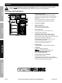
Controls and Indicators
1
2
3
4
5
6
7
8
POWER
ON
POWER CUTTING
CURRENT
MIN MAX
SET AIR
CUT
OVER
LOAD
OFF
ITEM 62204
0
30
60
90
120PSI
Figure C
1� Output Current Knob
Turn the Output Current Knob to the desired
current (15 to 40 amps)� Lower currents reduce
circuit breaker tripping� Adjust as needed after
test cuts�
Thicker material will use greater amperage�
Thinner material will use lower amperage�
2� Air Pressure Gauge
3� Digital Amp Meter
Shows actual cutting current,
which will vary during operation�
4� Power ON Light
Green light will be on when power is on�
5� Thermal Overload Light
Yellow light will be on if the Plasma Cutter
shuts down due to overload� Stop using the
Plasma Cutter while leaving the Power Switch ON
to allow the cooling fan to operate�
The light will turn off automatically when the
Plasma Cutter cools down.
Continue use while paying attention to
Duty Cycle discussed on page 10.
6� Cutting Light
Red light will be on during cutting operation�
7� Air Switch
CUT: For cutting operation.
SET AIR: Produces constant air flow for
SETTING AIR PRESSURE ONLY�
Not for cutting operation.
8� Power Switch & Circuit Breaker
Up is ON, down is OFF�
This switch also functions as a circuit breaker�
It will trip (disconnect power) if overcurrent occurs�
Turn OFF, then back to ON to reset it�

Page 9For technical questions, please call 1-888-866-5797.ITEM 62204
SAFETYOPERATIONMAINTENANCE SETUP
Preparation and Work Area
WARNING! Prevent eye injury and
burns. Wearing personal protective
equipment reduces the risk of injury.
1� Wear an ANSI‑approved welding helmet featuring
at least a number 10 shade lens rating�
Leather leggings, fire resistant shoes or
boots should be worn when using this
product� Do not wear pants with cuffs, shirts
with open pockets, or any clothing that can
catch and hold molten metal or sparks�
Keep clothing free of grease, oil, solvents,
or any flammable substances� Wear dry,
insulating gloves and protective clothing�
Wear an approved head covering to protect
the head and neck� Use aprons, cape, sleeves,
shoulder covers, and bibs designed and
approved for welding and cutting procedures�
Wear fire resistant ear plugs or ear
muffs to keep sparks out of ears�
Do not breathe arc fumes. Use natural
or forced air ventilation and wear a
NIOSH‑approved respirator�
WARNING! Prevent accidental fires. Remove
any combustible material from the work area.
2� Remove or make safe all combustible
materials for a radius of 35 feet (10 meters)
around the work area� Use a fire resistant
material to cover or block all open doorways,
windows, cracks, and other openings�
Enclose the work area with portable fire
resistant screens� Protect combustible
walls, ceilings, floors, etc�, from sparks
and heat with fire resistant covers�
3� The floor and surrounding area must not
be flammable� A clean concrete floor is
recommended�
The cutting process will eject
molten metal slag onto the floor, and it will
scatter for 8‑10 feet or more in all directions�
4� Keep multiple ABC-type fire
extinguishers near work area.
5� Place the Plasma Cutter on a sturdy, level surface
at least six feet from the work area�
Allow at least 18" around all sides of
the Plasma Cutter for air flow�
6� Put the workpiece on a sturdy metal work
table that is open below the cutting area�
Molten slag will be blown through the
workpiece, and must be able to fall away freely�
Mount the workpiece to be cut to the work table so
that the cutting debris falls to the concrete floor�
7� Set up Air Supply according to page 7�
8� Verify that the Power Switch is in the OFF position,
then plug the Plasma Cutter into an appropriate
240VAC outlet rated to at least 30 amps
to limit nuisance circuit breaker tripping�
9� PLASMA CUTTING TIPS:
Using a Plasma Cutter is a skill that
requires time and effort to do well�
a� Practice striking and maintaining an arc on
scrap work pieces before beginning work�
This will help determine the best settings for
the Plasma Cutter for the material at hand.
b� All metals that conduct electricity can
be cut, see Maximum Cutting Thickness
on page 5 for thickness capabilities�
Very thin or very thick metals are
more difficult to cut cleanly�
c� Set the air pressure between 60 and 80 PSI�
Increased air pressure will increase plasma
speed and cutting pressure� Air pressure and
amperage should be adjusted in tandem – air
pressure needs to increase as amperage
increases, however, low amperage cuts will
require less air pressure for a more stable cut�
d� Generally start with a mid‑range
amperage setting (32‑33 amps)
and adjust up or down from there�
Increased amperage will increase cutting heat�
This is needed with thicker and harder metals�
However, increased amperage will
reduce Duty Cycle time� (See page10.)
e� Move the Torch more slowly for thicker and
harder metals, and more quickly for thin or soft
metals� Keep the Torch moving while cutting�
Thicker Material
High Amps
More Air Pressure
Thinner Material
Low Amps
Less Air Pressure

Page 10 For technical questions, please call 1-888-866-5797. ITEM 62204
SAFETY OPERATION MAINTENANCESETUP
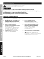
Basic Operation
PLASMA ARC CAN CAUSE SERIOUS INJURY,
INCLUDING SEVERE CUTS, BURNS, PERMANENT EYE DAMAGE AND BLINDNESS!
Once the trigger is squeezed, the arc will ignite IMMEDIATELY.
The Torch does not need to contact the workpiece before the pilot arc ignites.
Do not look at the Plasma Arc without an ANSI-approved welding helmet featuring at least a
number 10 shade lens rating.
1� BEFORE EACH USE, inspect the general
condition of the Plasma Cutter� Check for:
• loose hardware,
• damaged cord/electrical wiring,
• cooling fan operation,
• cracked or broken parts, and
• any other condition that may
affect its safe operation�
Have a qualified technician correct
any problems before operation�
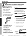
2� MAINTAIN TORCH COMPONENTS BEFORE
EVERY USE AND AFTER EVERY HOUR OF
OPERATION.
Make sure Torch is completely cool, then:
a� Disassemble Torch�
Electrode
Swirl Ring
Cutting Tip
Retaining Cup
b� Inspect the Cutting Tip.
Replace if interior is damaged, or if
opening is enlarged or gouged. Clean
inside as needed with steel wool, (remove
any pieces of steel wool afterwards)�
c� Inspect the Electrode.
Replace if pitted 1/16" or
more or if misshapen.
IMMEDIATELY REPLACE
COMPONENTS AS NEEDED.
d� Make sure all other internal torch components
are undamaged, clean, and free of debris�
e� After replacing parts as needed,
reassemble Torch tightly�
DO NOT USE WITH WORN COMPONENTS.
USING WORN COMPONENTS
WILL VOID THE WARRANTY AND
DAMAGE THE PLASMA CUTTER.
Duty Cycle
Duty Cycle is the equipment specification which
defines the number of minutes within a 10 minute
period that a piece of equipment can safely operate�
This Plasma Cutter has a 60% duty cycle at
40 amps, which means that it may be used only
6 minutes at 40 amps out of any 10 minute period,
and must be rested the remaining 4 minutes�
CAUTION: Failure to follow the duty cycle
limitations of this Plasma Cutter can easily damage
this equipment, and will void the warranty�
3� Securely attach the Ground Clamp to a part
of the workpiece or metal work table that is
clean, dry, and free from paint, oil, or dirt.
Clamp as close as possible to the planned
cut without exposing the Clamp to damage�
4� When everything is in place for cutting,
set the Power Switch to the ON position�
The green Power Light will illuminate,
but the Torch is not yet energized�
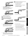
5� Orient yourself to one side of the cutting
area, and move the Welding Helmet
(sold separately) over your eyes�
keep
1/16" distance
from workpiece
90º
6� Position Torch near workpiece at start of cut�
Keep Cutting Tip at a 90º angle to workpiece,
and at 1/16" distance from workpiece�

Page 11For technical questions, please call 1-888-866-5797.ITEM 62204
SAFETYOPERATIONMAINTENANCE SETUP
7� Do not squeeze Trigger until Torch
is in position to start cutting.
Starting at the edge of the workpiece, squeeze
and hold the Trigger to strike the pilot arc�
When the arc ignites, start slowly moving
the Torch along your cut line�
8� Slowly move the Torch along the cutting
line with the Cutting Tip trailing�
Note: Keep the Torch Cutting Tip pointed
straight (90º) into the workpiece 1/16" from the
surface� Consistent workpiece distance and
cutting speed are critical� Sparks should pass
through the workpiece at a slight angle.
SLOW DOWN
if sparks do not pass
through workpiece
9� If sparks start shooting up from the workpiece
instead of passing through, the Torch is being
moved too quickly so the cut is not being
made completely� Move the Torch along the
workpiece more slowly to cut completely�
SPEED UP
if sparks pass straight
down through bottom
of workpiece
10� If sparks pass straight down through bottom of
workpiece instead of at a slight angle, the Torch
is being moved too slowly� This could cause the
arc to extinguish� Move the Torch a little faster�
Note: If the Plasma Cutter suddenly shuts off, check:
a� Torch distance from workpiece,
b� poor workpiece grounding,
c� dirty/painted workpiece,
d� Circuit Breaker & Power Switch tripping, or
e� Thermal Overload tripping.
(See number 5 on page 8.)
11� Pause briefly at end of cut�
12� Release the Trigger� The air will continue to come
out of the Torch for a few seconds once the Trigger
is released to cool off the Torch components�
13� When finished cutting:
a� Lift the Torch from the workpiece and set
down on a cool part of the metal work table,
b� Wait 10 minutes for the Plasma Cutter
to cool down with the Power Switch ON
so the fan continues to operate,
c� Press the Power Switch to the OFF position,
d� Turn the air supply off and disconnect air lines,
e� Unplug the Power Cord from the electrical outlet�

Page 12 For technical questions, please call 1-888-866-5797. ITEM 62204
SAFETY OPERATION MAINTENANCESETUP
Maintenance Instructions
Procedures not specifically explained in this manual
must be performed only by a qualified technician.
TO PREVENT SERIOUS INJURY FROM ACCIDENTAL OPERATION OR ELECTRIC SHOCK:
Make sure the Power Switch of the Plasma Cutter is in its "OFF" position and that the Plasma Cutter is
unplugged from the electrical outlet before performing any inspection, maintenance, or cleaning procedures.
TO PREVENT SERIOUS INJURY FROM PLASMA CUTTER FAILURE:
Do not use damaged equipment. If abnormal noise, vibration, or leaking
air occurs, have the problem corrected before further use.
Cleaning and Maintenance
Note: These procedures are in addition to the regular checks and maintenance
explained as part of the regular operation of the air‑operated tool�
1� BEFORE EACH USE, disassemble Torch,
inspect and replace worn components,
then reassemble Torch tightly according
to number 2 on page 10�
2� Daily - Air Supply Maintenance:
Every day, maintain the air supply according
to the component manufacturers' instructions�
Drain the dryer regularly.
Performing routine air supply maintenance
will allow the tool to operate more safely
and will also reduce wear on the tool�
3� PERIODICALLY, blow the dust from the
cooling vents with compressed air�
4� If the unit repeatedly shuts down
from thermal overload, stop all use�
Have the Plasma Cutter inspected and
repaired by a qualified service technician�
5� Opening the Plasma Cutter will void the
warranty, and may result in damage to
equipment or possible personal injury.
DO NOT OPEN THE HOUSING.
Any repairs must be completed
by a qualified technician�
6� Store the Plasma Cutter and accessories in a
clean and dry location out of reach of children�
7� WARNING! If the supply cord of this
Plasma Cutter is damaged, it must be replaced
only by a qualified service technician.

Page 13For technical questions, please call 1-888-866-5797.ITEM 62204
SAFETYOPERATIONMAINTENANCE SETUP
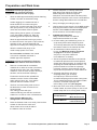
Troubleshooting
IMPORTANT!
Be CERTAIN to shut off the Plasma Cutter, and disconnect it from power and air before adjusting, cleaning,
or repairing the unit. A technician should discharge all capacitors before performing any internal procedures.
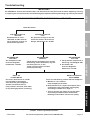
Air pressure too high or too low.
Check the Cutter's Air Pressure
Gauge. Set between 60 - 80 PSI.
Set Compressor's Air
Pressure Regulator
between 90 - 120 PSI.
FAN RUNS WHEN SWITCHED ON BUT ARC WILL NOT IGNITE
AIR PRESSURE
TOO HIGH
AIR PRESSURE
TOO LOW
a. Verify that the compressor is
delivering 4.5 CFM @ 80 PSI.
b. Set Cutter's Air
Pressure Regulator
between 60 - 80 PSI.
AIR PRESSURE
CORRECT
If the steps above do not solve the problem or if the repairs involved are too
complex, contact a qualified technician.
Check that the grounding point and the
metal being cut are both clean, dry, and
free from paint, oil, or dirt.
These sections need to conduct
electricity efficiently.
Use a wire wheel brush or sander
(not included) to thoroughly
clean both the grounding point
and the area that will be cut.
If any cleaners are used, allow them
to dry thoroughly before continuing.
Set Air Switch to "CUT".
"SET AIR" is ONLY used to
set air pressure. It does not
allow normal operation.
DIRTY OR
COATED METAL
AIR SWITCH SET TO
"SET AIR"
Check Air Switch
METAL IS CLEAN IN
BOTH AREAS
AIR SWITCH SET TO
"CUT"
Torch isn’t maintaining contact with the workpiece.
a. Maintain a 1/16" distance
from workpiece at all times.
b. Disassemble Torch, inspect and replace worn
components, then reassemble Torch tightly
according to number 2 on page 10.
c. Torch is moving too slowly across the metal
and cutting the material from underneath,
breaking contact. Move Torch more quickly.

Page 14 For technical questions, please call 1-888-866-5797. ITEM 62204
SAFETY OPERATION MAINTENANCESETUP
Troubleshooting (cont.)
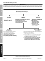
Air pressure too high or too low.
Check the air pressure setting on
both the Compressor and the Cutter.
Set Compressor's Air
Pressure Regulator
between 90 - 120 PSI.
AIR PRESSURE
TOO HIGH
AIR PRESSURE
TOO LOW
a. Verify that the compressor is
delivering 4.5 CFM @ 80 PSI.
b. Set Cutter's Air
Pressure Regulator
between 60 - 80 PSI.
c. Verify air flow by
performing "Test Air
Flow:" on page 7.
Use a wire wheel brush or sander
(not included) to thoroughly
clean both the grounding point
and the area that will be cut.
If any cleaners are used, allow them
to dry thoroughly before continuing.
DIRTY OR
COATED METAL
METAL IS CLEAN IN
BOTH AREAS
Torch isn’t maintaining contact with the workpiece.
a. Maintain a 1/16" distance
from workpiece at all times.
b. Disassemble Torch, inspect and replace worn
components, then reassemble Torch tightly
according to number 2 on page 10.
c. Torch is moving too slowly across the metal
and cutting the material from underneath,
breaking contact. Move Torch more quickly.
AIR PRESSURE
CORRECT
IMPORTANT!
Be CERTAIN to shut off the Plasma Cutter, and disconnect it from power and air before adjusting, cleaning,
or repairing the unit. A technician should discharge all capacitors before performing any internal procedures.
If the steps above do not solve the problem or if the repairs involved are too
complex, contact a qualified technician.
ARC IGNITES FOR SEVERAL SECONDS BUT THEN GOES OUT
Check that the grounding point and the
metal being cut are both clean, dry, and
free from paint, oil, or dirt.
These sections need to conduct
electricity efficiently.

Page 15For technical questions, please call 1-888-866-5797.ITEM 62204
SAFETYOPERATIONMAINTENANCE SETUP
Troubleshooting (cont.)
IMPORTANT!
Be CERTAIN to shut off the Plasma Cutter, and disconnect it from power and air before adjusting, cleaning,
or repairing the unit. A technician should discharge all capacitors before performing any internal procedures.
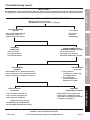
If the steps above do not solve the problem or if the repairs involved are too
complex, contact a qualified technician.
Take note of the
setting required for
this metal thickness.
CUT GOES ONLY PARTIALLY THROUGH THE WORKPIECE
Air pressure too low.
Set Cutter's Air Pressure
Regulator between 60 - 80 PSI.
Turn up the Output Current
Knob and try again at a
slower Torch travel speed.
Material being cut is too thick.
See Maximum Cutting Thickness on page 5.
Use a more
powerful
Plasma Cutter.
WITHIN THICKNESS
RANGE
TOO THICK
a. Verify that the
compressor is delivering
4.5 CFM @ 80 PSI.
b. Set Cutter's Air
Pressure Regulator
between 60 - 80 PSI
AIR PRESSURE
CORRECT
AIR PRESSURE
TOO LOW
PROBLEM
CORRECTED
PROBLEM PERSISTS AT
MAXIMUM CURRENT SETTING
Disassemble Torch, inspect and replace
worn components, then reassemble Torch
tightly according to number 2 on page 10.
Disassemble Torch, inspect and
replace worn components, then
reassemble Torch tightly according
to number 2 on page 10.
TORCH IN GOOD
CONDITION
DAMAGED
COMPONENTS FOUND
Cut at a slower pace, the arc
may not have enough time to
cut through the workpiece.
Maximum cutting speeds:
3/8" Mild Steel @ 10 IPM (Rated)
5/8" Mild Steel @ 5 IPM (Severence)

Page 16 For technical questions, please call 1-888-866-5797. ITEM 62204
SAFETY OPERATION MAINTENANCESETUP
Troubleshooting (cont.)
IMPORTANT!
Be CERTAIN to shut off the Plasma Cutter, and disconnect it from power and air before adjusting, cleaning,
or repairing the unit. A technician should discharge all capacitors before performing any internal procedures.
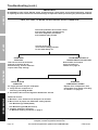
If the steps above do not solve the problem or if the repairs involved are too
complex, contact a qualified technician.
Current set too high;
cut at lowest setting possible
for the metal being cut.
FAST CUTTING TIP WEAR OR EXCESSIVE SLAG FORMATION
Take into account the thickness
and type of metal to be cut
before starting. Thinner materials
require lower amp settings.
PROBLEMS
REDUCED
Disassemble and inspect
Torch according to
number 2 on page 10.
Replace worn components, then
reassemble Torch tightly according
to number 2 on page 10.
TORCH IN GOOD
CONDITION
DAMAGED
COMPONENTS FOUND
Air supply pressure may be inadequate:
a. Verify that the compressor is
delivering 4.5 CFM @ 80 PSI.
b. Set Cutter's Air Pressure Regulator between 60 - 80 PSI.
Additional factors:
a. Maintain a 1/16" distance from workpiece at all times.
b. Move Torch at proper rate. Maximum cutting speeds:
3/8" Mild Steel @ 10 IPM (Rated)
5/8" Mild Steel @ 5 IPM (Severence)
c. Compare workpiece thickness
to Maximum Cutting Thickness on page 5.
These two problems have similar causes
and will often appear simultaneously.
The same diagnostic procedures
and remedies apply to both.
PROBLEMS PERSIST AT
LOWEST PRACTICAL SETTING

Page 17For technical questions, please call 1-888-866-5797.ITEM 62204
SAFETYOPERATIONMAINTENANCE SETUP
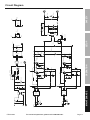
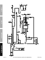
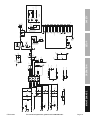
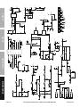
Circuit Diagram
L2
*
+OUT*
-OUT*
+HT
V1-
1
23
4
BK
*
V2-
V2+
V1+
T2
*
1
1
2
2
T2
*
电流采样
J
8_3P
(PWM)
Mess_I
C18V
+HT
VCC
AC1
AC2
J2
*
*
VCC
GAS
BR5006
EART
H
1/4
R8
180K
1/4
R9
180K
C1
1UF-275V
1/4
R2
200K
1/4
R10
270K
1/2
R7
120R
C36
10NF-630V
~
1
~
3
-
4
+
2
BGR
BR5006
C9
680UF-400V
C3
680UF-400V
C2
680UF-400V
1/4
R24
1K
NC
1
ANODE
2
CATHODE
3
NC
4
VEE
5
VO
6
VO
7
VCC
8
ISO2
A3120
NC
1
ANODE
2
CATHODE
3
NC
4
VEE
5
VO
6
VO
7
VCC
8
U?
A3120
1/4
R28
1K
1/4
R14
1K
1/4
R15
1K
C22
3.3NF-1600V
1/4
R22
1K
DZ2
C10V
DZ1
C10V
C27
3.3NF-1600V
D14
RHRP1560
D20
RHRP1560
1/4
R11
10R
1/4
R12
10R
1/4
R17
10R
1/4
R18
10R
1/4
R19
1K
5
R52
3.3K
5
R55
3.3K
3
4
5
K2B
12VDC16A
J
2 1
K2A
12VDC16A
J
2 1
K1A
12VDC30A
3
4
K1B
12VDC30A
12
R1
R12W-47Ω-5%
L1
T25*15*10-9.5-Φ1.4
D36_1
RHRG30120
D37_1
RHRG30120
D38_2
RHRG30120
D38_1
RHRG30120
C23
100NF-63V
C6
4.7NF-250V
C5
4.7NF-250V
C26
100NF-63V
J1
DZ6
18V
DZ5
18V
DZ4
DZ3
18V
DZ9
18V
DZ7
18V
DZ10
18V
DZ8
18V
v
RV1
MYG511KD14
1/2
R26
1K
1/2
R23
1K
C50
4.7NF400V
C51
4.7NF400V
D33
1N4007
D10
1N4007
1/4
R16
10R
1/4
R40
10R
D1
HER307
D2
HER307
C7
100PF-63V
C8
100PF-63V
D4
1N4148
D3
1N4148
C24
47UF-50V
C25
47UF-50V
C28
47UF-50V
C29
47UF-50V
Q1_1
FGH60N60SFD
Q1_2
FGH60N60SFD
Q2_1
FGH40N60SFD
Q2_2
FGH40N60SFD
C4
CBB21-1UF-630V
14
R21
R14W-10Ω-5%
14
R27
R14W-10Ω-5%
C53
CBB-2.2NF-1600V
C43
CBB-2.2NF-1600V
14
R53
R14W-22Ω-5%
14
R45
R14W-22Ω-5%
14
R54
R14W-22Ω-5%
OUT-

Page 18 For technical questions, please call 1-888-866-5797. ITEM 62204
SAFETY OPERATION MAINTENANCESETUP
1
2
FAN*
V3+
V3-
V2+
V2-
V1+
+HT
Vref
Vf
Vref
Vf
Vf
VCC
V1-
C11
100N
D6
ER2D
D30
ER2D
D8
ER2D
C31
100N
C14
100N
D32
ER2D
D9
ER2D
C013
22UF-50V
C39
100N
C42
220UF-63V
3
R03
3W-10K
1/2
R04
1/2W-100R
C014
4.7NF-630V
C017
100UF-35V
D012
18V
1/4
R016
43K
1/4
R014
150K
1/4
R034
1K
1/4
R033
4.3K
1/4
R015
22K
IN
3
Adj
1
OUT
2
Q03
LM317
C38
100UF-35V
COMP
1
VF
2
CS
3
RT/CT
4
GND
5
OUT
6
VCC
7
Vref
8
U1
UC3842BN
1
2
12
10
7
85
6
11
9
T1
EC2834-88:13:23:23:11-Φ0.25-L
Q02
STP6N95K5
C021
470PF-50V
C019
470PF-50V
C020
47NF-50V
C015
100NF-275V
1/4
R25
2.2K
1/4
R29
240R
1/2
R07
56K
1/2
R08
56K
1/2
R09
56K
1/4
R011
47R
D014
ER2D
D013
ER2D
1/4
R012
10K
D011
1N4148
C018
100NF-100V
C016
100NF-100V
C022
1NF-50V
C13
47UF-50V
C10
47UF-50V
C35
47UF-50V
1/4
R021
3Ω
1/4
R018
3Ω
1/4
R013
3Ω
2
R010
RJ2W-1Ω-5%
D010
BYV26E
1/4
R48
100k

Page 19For technical questions, please call 1-888-866-5797.ITEM 62204
SAFETYOPERATIONMAINTENANCE SETUP
OUT+
J11
J11
J11
OUT+
ISO1_3
ISO1_3
V3+
V3-
V3+
J14
J13
V3-
J8-18
GUN
Ig
C_PWM
1
1
2
2
ST
�保�开关
1
1
2
2
ST1
�保�开关
VCC
J8_10P
OVER_HOT
J8_17P
D35
OVER?
D2
POWER
D26
HOT
VCC
J8_16P
HOT_POWER
J8_9P
J8_14P
1 2 3 4 567 8 9 10 11 12 13 14 15 16 17 18 19 20
J8
CZ-21
J8_1P
J8_2P
PWM
GAS
OVER_HOT
J8_9P
J8_10P
Ig
HOT_POWER
C_PWM
J8_14P
J8_16P
J8_17P
GUN
D40
IN4007
J8_2P(LV)
+HT
J8_1P(OV)
VCC
J8-18
Mess_I
1
2
3
VR1
50K
1
2
3
4
5
6
7
J1
CON7
1
2
3
4
5
6
7
J_3_2
CON7
J8_10P(
5V)
VCC
J8_16P
HOT_POWER
J8_16P
VCC
HOT_POWER
C37
10nF
前面板
1/2
R4
300k
1/2
R3
270k
1/2
R5
270k
1/2
R6
270k
C58
X1Y1-3.3NF-250V
OUT-
1/4
R35
20k
1/4
R13
15k
VR2
50k
IN
1
GND
2
+5V
3
U2
L7805
VCC
C48
100UF-35V
C63
100n
+5V
2
3
84
U3A
LM358
VCC
C63
100n
C67
100n
6
5
7
U3B
LM358
1/4
R75
100k
1/4
R71
100k
VR3
100k
C55
100n
1
2
3
4
J3
2.54*4
+5V
1
2
J2
2*2.54
VCC
D015
1N4148
0
1/4
R63
4.7k
1/4
R67
10k
C47
100n
Q1
BC817-25
1/4
R64
390
1
1
2
2
ST4
�保�开关
C79
100n
C71
100n
1/4
R36
0
C75
100n
1/4
R31
390
1/4
R47
5.6k
C32
100n
D54
1N4148
D22
C4V7
D55
1N4148
1/4
R60
5.6k
C44
100n
1/4
R46
560
D56
1N4148
C34
100n
1/4
R49
120
D59
BAT42W
C52
470UF-35V
1/4
R57
5.6k
C33
100n
D57
1N4148
1/4
R59
0
12
R43
R12W-0.47Ω-5%
12
R44
R12W-0.47Ω-5%
1/4
R51
0
C46
100n
C41
*
1/4
R39
120k
1/4
R38
150
2
R37
RJ2W-47Ω-5%
1/4
R56
1k
1/4
R32
33k
1/4
R33
330k
C40
1UF-100V
A
1
K
2
A
3
K
4
A
5
K
6
A
7
K
8
E
9
C
10
E
11
C
12
E
13
C
14
E
15
C
16
ISO1
TLP621-4
R42
10K
1/4
R8
1.8k
1/4
R36
1.8K
1/4
R50
1.8k

Page 20 For technical questions, please call 1-888-866-5797. ITEM 62204
SAFETY OPERATION MAINTENANCESETUP
PWM
C_PWM
VCC_R
Q17_2P
P_Test
VCC
J8_2P
VCC
J8_1P
HOT_POWER
Q13
2N7002
Ig1
Q12
2N7002
VREF
1
2
3
U4A
4093
Ig
Mess_I
VREF
1 2
U3A
40106
3
4
U3B
40106
5
6
U3C
40106
89
U3D
40106
10
11
U3E
40106
12
13
U3F
40106
GUN
VCC Trigger1
Reset1
123 4567 8 9 10 11 12 13 14
15 16 17 18 19
20
J8
CZ-21
Discharge
1
Threshold
2
Control V
3
Reset
4
Output
5
Trigger
6
GND
7
Trigger
8
Output
9
Reset
10
Control V
11
Threshold
12
D charge
13
VCC
14
U5 LM556
+
C33
3.3uF 100V
C23 10nF
556_OUT2
VCCGUN
VCC
556_OUT2
VCC
VCC
J8_17P
U3_10P
U4_11P
IF
HOT_POWER
GND
J8_2P
PWM
J8_10P
C_PWM
J8_1P
Ig
Mess_I
Q17_2P
556_OU1
C22
2.3nF
U3_10P
R46
470
VCC
VCC_R
Reset2 Rest2
Rest1
Trigger1
Rest2
556_OU
T1
5
6
4
U4B
4093
8
9
10
U4C
4093
12
13
11
U4D
4093
J8_17P
U4_11P
VCC
J8_16P
J8_16P
GAS
GAS
Mess_I
OVER_HOT
OVER_HOT
J8_9P
J8_9P
J8_14P
J8_14P
VREF
Ig1
ERR_I
ERR_I
VCC
Rest1
1/8
R42
1K
1/8
R33
270K
1/8
R32
1K
1/8
R47
82K
1/8
R41
1K
1/8
R45
1K
1/8
R39
1K
1/8
R24
1K
1/8
R35
1K
1/8
R59
1K
1/8
R53
1K
1/8
R34
4.7K
1/8
R3
1K
1/8
R7
1K
1/8
R6
1K
1/8
R5 1K
1/8
R19
10K
1/8
R17
10K
1/8
R18
10K
1/8
R15
1K
1/8
R62
10K
1/8
R20
1K
1/8
R31
1K
1/8
R54
100R
1/8
R61
100R
1/8
R37
100R
1/8
R30
100R
1/8
R43
100R
1/8
R51
4.7K
1/8
R56
4.7K
1/8
R57
4.7K
1/8
R9
4.7K
1/8
R49
4.7K
1/8
R8
4.7K
1/8
R48
4.7K
1/8
R41
110K
1/8
R38
4.7K
1/8
R40 330R
1/8
R26
47K
1/8
R4
10K
1/8
R11
10K
1/8
R2
22K
1/8
R1
68K
1/8
R50
4.7K
1/8
R27
0R
1/8
R36
680R
1/8
R28
270K
1/8
R52
470R
1/8
R55
820K
1/8
R60
390K
1/8
R58
47K
1/8
R16
22K
1/8
R22
18K
1/8
R21
4.7K
1/8
R23
47R
1/8
R10
7.15K
C28
100N
C15
100N
C2
100N
C1
100N
C19
100N
C20
100N
C25
10N
C6
10N
C7
10N
C8
100N
C12
100N
C16
10N
C24
10N
C3 100N
C5
1N
C10
1N
C9
10N
C27
100N
C4
100N
1/8
R13
13K
C21
100N
C13
1N
C26
100N
C17
100P
C18
100P
C14
470P
D6
1N4148
D7
1N4148
D8
1N4148
D5
1N4148
D2
1N4148
D3
1N4148
D1
1N4148
D9
1N4148
D4
1N4148
D20
BAV99
D17
BAV70
D15
BAV70
D14
BAV70
D18
BAV70
D19
BAV99
Q9
BAV70
D13
4.7V
D10
4.7V
D11
4.7V
C31
1UF-50V
C32
3.3UF-100V
C30
4.7UF-100V
C29
47UF-35V
Q19
BC817-25
Q4
BC817-25
Q5
BC817-25
Q20
BC817-25
Q17
BC817-25
Q11
BC817-25
2
3
1
411
U1A
MC33074D
6
5
7
U1B
MC33074D
9
10
8
U1C
MC33074D
13
12
14
U1D
MC33074D
1/8
R25
14k
1/8
R29
16k
1/8
R14
43k
D16
BC807-25
0
AIR-SET
AIR-SET
D12
24V
COMP
1
VF
2
CS
3
RT/CT
4
GND
5
OUT
6
VCC
7
Vref
8
U2
UC3845BD1R2G
Page is loading ...
Page is loading ...
Page is loading ...
Page is loading ...
-
 1
1
-
 2
2
-
 3
3
-
 4
4
-
 5
5
-
 6
6
-
 7
7
-
 8
8
-
 9
9
-
 10
10
-
 11
11
-
 12
12
-
 13
13
-
 14
14
-
 15
15
-
 16
16
-
 17
17
-
 18
18
-
 19
19
-
 20
20
-
 21
21
-
 22
22
-
 23
23
-
 24
24


Harbor Freight Tools 240 Volt Inverter Plasma Cutter with Digital Display Owner's manual
- Category
- Welding System
- Type
- Owner's manual
- This manual is also suitable for
Ask a question and I''ll find the answer in the document
Finding information in a document is now easier with AI
Related papers
-
Chicago Electric Item 96464 Owner's manual
-
Harbor Freight Tools 18 Oxygen / Acetylene Cutting Torch User manual
-
-
-
Harbor Freight Tools Butane Pencil Torch User manual
-
Other documents
-
WARRIOR Item 56433 Owner's manual
-
Klutch P600iHD Owner's manual
-
PROCRAFT 511468 Operating Instructions Manual
-
-
Stark 55137 User manual
-
Chicago Electric 58605 Owner's manual
-
-
-
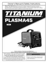 Titanium Item 56255 Owner's manual
-
Parkside PPSK 40 A2 Plasma Cutter User manual
