Page is loading ...

191933 12/9/96
IMI CORNELIUS INC.
One Cornelius Place
Anoka. MN 55303-6234
Telephone (800) 238--3600
Facsimile (612) 422--3246
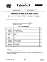
INSTALLATION INSTRUCTIONS
KIT, P/N 2306
For installing Scotsman Model CM450, 500, & 650 Series Ice Makers on Remcort Model DB200 Series Ice/
Drink dispenser.
1. Bin Level Control
A. Locate and drill three (3) 5/16” diameter holes (Ref. Fig. 1).
B. Install mounting clamps.
2. Seal ice maker to top of Dispenser as follows:
A. Run a bead of RTV on the dispenser cover around the outline of the ice maker and inside edge of cov-
er opening.
B. Set ice maker onto cover and install bin level thermostat capillary tube in clamps and tighten screws
(Ref. Fig 1). Position ice maker as shown.
C. Wipe away excess RTV.
3. Secure ice maker to Dispenser with mounting brackets as show. Drill holes and install sheet metal screws
provided into ice maker cabinet and dispenser cover. Screws must not interfere with ice maker compo-
nents.
4. Install adhesive backed gasket strip to removable lid, and install with screw provided.
5. Follow the manufacturer’s instructions to complete the installation of the ice maker. Bin level thermostat
capillary tube must not interfere with agitator.

2 9193312/9/96
2808028080
2808028080
24
30
ROUTE ICEMAKER BIN LEVEL
THERMOSTAT CAPILLARY TUBE
AS SHOWN. INSTALL ON
HOPPER AS SHOWN IN FIG. 1
ICEMAKER TO BE
FLUSH WITH BACK
EDGE OF COVER.
APPLY RTV AROUND INSIDE
OF ICEMAKER OUTLINE ON
DISPENSER COVER TO
FORM A SEAL.
REMOVE SCREWS AND TURN
BRACKETS AROUND 180_.
REPLACE SCREWS. USING
BRACKET AS TEMPLATE,
DRILL (4) .136 DIA. HOLES
INTO ICEMAKER CABINET
FOR SHEET METAL SCREWS
PROVIDED. DRILLING IS NOT
TO INTERFERE WITH
ICEMAKER COMPONENTS.
REMOVABLE FRONT LID
FOR MANUAL ICE FILLING.
ADD ADHESIVE BACKED GAS-
KET STRIPS TO REMOVABLE LID.

391933 12/9/96
15”
4--5/8
1”
DRILL 5/16 DIA. HOLES FOR 8--32
WELD NUT
PLASTIC TUBING
USE AS REQUIRED
LARGE CLAMP
(IF NEEDED)
CAPILLARY TUB-
ING
TOP-
VIEW
6
ICEMAKER
FRONT WALL
OF HOPPER
THERMOSTAT
CAPILLARY TUBE
1--5/8
INSERT 8-32 WELL NUTS INTO 5/16
DIA. HOLES, TIGHTENING SCREWS
WILL SECURE
BIN LEVEL THERMOSTAT CAPILLARY
TUBING ASSEMBLY
LOCATE AND ADD
CLAMP HOLE IF
NEEDED TO RETAIN
CAPILLARY TUBING
/