
QUANTUM SERIES
VERSION 4
OWNER’S MANUAL
The Coolest Thing In Wine Storage
Quantum SS9000
Quantum SS12000
24V Thermostat Conversion Kit Option

Copyright © 2012. WhisperKOOL. All rights reserved.
WhisperKOOL copyrights this manual, the product design, and the design concepts, with all rights reserved. Your rights
with regard to the hardware and manual are subject to the restrictions and limitations imposed by the copyright laws of
the USA. Under copyright laws, this manual may not be copied, reproduced, translated, transmitted, or reduced to any
printed or electronic medium or to any machine-readable form, for any purpose, in whole or in part, without the written
consent of WhisperKOOL.
Every effort has been made to ensure that the information in this manual is accurate. WhisperKOOL is not responsible for
printing or clerical errors.
WhisperKOOL reserves the right to make corrections or improvements to the information provided and to the related
hardware at any time, without notice.
Vinothèque and WhisperKOOL are registered trademarks, and ECE is a trademark of WhisperKOOL. All rights reserved.
Mention of third-party products is for informational purposes only and constitutes neither an endorsement nor a
recommendation. WhisperKOOL assumes no liability with regard to the performance or use of these products.
We manufacture, test and certify 100% of our wine cooling units in
the USA. By sourcing the best components and closely controlling our
manufacturing processes, we can assure the highest-quality,
lowest defect manufacturing rates in the industry.
Conforms to ANSI/UL Std 427
Certied to CAN/CSA Std C22.2 No. 120

TABLE OF CONTENTS
Introduction ................................................ 3
Before You Start ............................................ 4
Receiving & Inspecting the System ......................... 5
Quick Reference Guide
Unit & Knockout Locations ............................... 6
Condensate Drain Pan .................................... 7
Unit Specications ....................................... 8
Preparing the Wine Cellar ................................... 9
System Operation. . . . . . . . . . . . . . . . . . . . . . . . . . . . . . . . . . . . . . . . . . . 12
WhisperKOOL Troubleshooting Guide ...................... 15
Maintenance Schedule ..................................... 17
Technical Assistance ........................................ 19
Installation Terms & Conditions ............................ 20

Page 2 | 1-800-343-9463
QS 020519
WARNING
Failure to follow the instructions provided in this manual may result in a poor
vapor barrier, water damage, rust, and/or system corrosion and will void the warranty
on your unit.
The evaporator unit (fan coil unit) must be insulated using fiberglass insulation (R19 or
higher). This includes the cavity between the ceiling joists (if the unit is installed in an attic).
A warm environment will reduce the capacity of the cooling system, as the system will absorb
heat from the environment in addition to the heat load from the wine cellar. This, in effect,
will significantly reduce the cooling system’s ability to cool the wine cellar.
Failure to properly insulate the evaporator unit may cause condensation to form on the
surface of the housing and water damage to the surrounding space, the cooling unit, and
possibly the wine cellar.
To avoid these issues, insulate any surface of the evaporator unit located outside of the wine
cellar using fiberglass insulation with a rating of R19 or higher.
Additional insulation is REQUIRED.

www.whisperkool.com | Page 3
Quantum Series
WARRANTY REGISTRATION
In order to activate the warranty of your system, the verication and operational
documentation must be completed by the certied refrigeration technician
installing your system and submitted via mail, fax, or e-mail.
Mail to:
WhisperKOOL
ATTN: Warranty Registration
1738 E. Alpine Avenue
Stockton, CA 95205-2505
USA
Fax to:
209-466-4606
Scan and email to:
INTRODUCTION
Customer Service
Thank you for purchasing a WhisperKOOL cooling system. We strive to provide the highest-quality products and the best
possible customer service. If you have any questions about your system, please call us at 1-800-343-9463 or visit
WhisperKOOL.com.
Using the Manual
This manual is intended to assist in the proper maintenance of the cooling system. In order to ensure the longevity of your
cooling unit, the equipment should be installed as outlined in the technician’s manual. It is also vital to establish a proper care
and maintenance schedule. Please read and review this manual carefully and keep it for future reference.
What is the WhisperKOOL Cooling System?
The WhisperKOOL cooling system is a specialized refrigeration system designed for one purpose only: to maintain the optimal
temperature and humidity levels conducive to the proper storage and aging of ne wines. This system produces minimal in-cellar
noise and has the most lenient exhaust requirements. An exterior housing is required for outdoor condensing unit installations.
How Does the Cooling System Work?
Similar to the air conditioning systems used for homes, the evaporator unit and condensing units are installed in separate
locations and are connected by a refrigerant line set. The evaporator portion is commonly installed in the wine cellar, with the
condensing unit is located either outside or in a remote indoor location that is ventilated. An exterior housing is required for
outdoor condensing unit installations.
Temperature Setting
The system is designed to maintain a cellar temperature of 55°F as long as the ambient temperature does not exceed 110°F.

Page 4 | 1-800-343-9463
QS 020519
BEFORE YOU START
1-800-343-9463
1. Inspect the system before installation. If damage is found, please contact your distributor or WhisperKOOL Customer Service
at 1-800-343-9463.
2. The Quantum evaporator unit requires a dedicated 115V, 15-amp circuit.
3. The 9000 condensing unit requires a dedicated 230V, 15-amp, single-phase circuit. Use a surge protector with the unit. Do not
use a GFI (ground fault interrupter) line.
4. The 12000 condensing unit requires a dedicated 230V, 20-amp, single-phase circuit.
5. No communication cables are required between the evaporator and condensing units.
6. A standard 18-5 thermostat wire must be run from evaporator unit to the thermostat.
7. You are REQUIRED to install a drain line to remove condensation from the evaporator unit.
8. The warranty is not active until a warranty checklist has been received, reviewed, and approved.
9. The system is intended for use in properly designed and constructed wine cellars. Hire a professional wine storage consultant
with a valid contractor’s license to build your wine cellar.
10. WhisperKOOL requires that all split systems be installed by a certified HVAC-R technician only. NATE or equivalent is
recommended.
If you encounter a problem with your WhisperKOOL system, please refer to the Troubleshooting Guide. If you have any further
questions or concerns, or need assistance, please contact WhisperKOOL’s Customer Service at 1-800-343-9463. Please be sure all
testing has been completed prior to contacting Customer Service. Please have your results ready for your representative.

www.whisperkool.com | Page 5
Quantum Series
Upon receiving your WhisperKOOL unit:
• Use caution when lifting and check the package for damage.
• Lift only at the designated hand-hold locations on the shipping container, or fully support the unit from underneath. A
shipment may include one or more boxes containing accessories.
• Inspect the packaging for any obvious signs of damage or mishandling before opening the container.
• Note any discrepancies or visual damage on the bill of lading before signing.
• Sit unit upright for 24 hours.
• Review the packing slip to verify contents.
• Check the model number to ensure it is correct.
• Check that all factory options ordered are listed.
If any items listed on the packing slip do not match your order information,
contact WhisperKOOL Customer Service immediately.
RECEIVING & INSPECTING THE SYSTEM
Please leave the unit in its original box until you are ready for installation. This will allow you to move the product safely without
damaging it. When you are ready to remove the product from the box, refer to the installation instructions.
TIP: Save your box and all packaging materials. They provide the only safe means of transporting/shipping the unit.
Verify that the pallet you’ve received contains the following:
(1) Evaporator box (1) Square-to-round plenum box
(1) Condensing unit box
1. Verify that the evaporator unit box contains the following:
• (1) Quantum evaporator unit
• (1) Foam fan bracket
• (1) Quantum owner’s manual
• (1) Quantum technician’s manual
• (2) Rubber grommets (⁄” ID)
• (1) Strip of cork tape (1”)
• (1) Split system warranty checklist
• (18) Antimicrobial pan tabs
• (1) Drain line brush
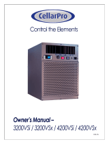
2. Verify that the condensing unit box contains the following:
• (1) Quantum SS9000 condensing unit OR
(1) Quantum SS12000 condensing unit (depending on unit ordered)
• (1) 6-1 ¾” PVC male adapter
• (1) Sight glass
• (1) Filter drier
3. Verify that the square-to-round plenum box contains the following:
• (1) Square-to-round plenum
• (8) #10-16 x ½” steel drilling screws
NOTE: WhisperKOOL units are manufactured in
the USA and tested prior to shipment.
Pictured: SS9000 condensing unit.

Page 6 | 1-800-343-9463
QS 020519
QUICK REFERENCE GUIDE
Line set knockout
options
Power supply knockout
Drain port
Interchangeable
panels
Thermostat cable knockout
Return air
Supply air
Line set knockout
options
Power supply knockout
Thermostat connection

www.whisperkool.com | Page 7
Quantum Series
CONDENSATE DRAIN PAN
Check local codes and regulations (regarding the disposal of condensates) for specic installation requirements. A separate drain line
will need to be installed. Please see the technician’s manual for more info.

Page 8 | 1-800-343-9463
QS 020519
Model SS9000 Evaporator Unit SS9000 Condensing Unit
Cellar Size Approx. 3000 cu. ft. when cellar is fully insulated and sealed with a proper vapor barrier*
BTU/h w/85°F air entering
condenser coil
9572
Dimensions 29.5”L x 30.9”W x 19.8”H 24”L x 18.98”W x 16.16”H
Refrigerant R-134a
HP 3.76
Voltage Rating 115V (15-amp dedicated circuit required) 230V (15-amp dedicated circuit required)
Weight (lbs) 96 75
Amps Evaporator: 3.2 (running amps), compressor: LRA 35, RLA 6.5
Duct Kit 14” supply, 14” return
Drain Line ¾” ID CPVC
Installation
Evaporator can be installed up to 25 duct feet away from the cellar with 14” ex duct. Condensing
unit can be installed up to 100 line feet from evaporator unit.
Thermostat Aftermarket (24V thermostat not included)
Temp. Delta Can maintain a 55°F cellar temperature with up to 110°F condesner air intake temperature
Warranty 2 years (parts and labor)
QUANTUM SS9000 SPECIFICATIONS
QUANTUM SS12000 SPECIFICATIONS
Model SS12000 Evaporator Unit SS12000 Condensing Unit
Cellar Size Approx. 4000 cu. ft. when cellar is fully insulated and sealed with a proper vapor barrier*
BTU/h w/85°F air entering
condenser coil
12530
Dimensions 29.5”L x 30.9”W x 19.8”H 24”L x 19.4”W x 16.1”H
Refrigerant R-134a
HP 5
Voltage Rating 115V (15-amp dedicated circuit required) 230V (15-amp dedicated circuit required)
Weight (lbs) 96 85
Amps Evaporator: 3.2 (running amps), compressor: LRA 56, RLA 12
Duct Kit 14” supply, 14” return
Drain Line ¾” ID CPVC
Installation
Evaporator can be installed up to 25 duct feet away from the cellar with 14” ex duct. Condensing
unit can be installed up to 100 line feet from evaporator unit.
Thermostat Aftermarket (24V thermostat not included)
Temp. Delta Can maintain a 55°F cellar temperature with up to 110°F condesner air intake temperature
Warranty 2 years (parts and labor)
*See note on following page,
“Sizing the Unit to the Room.”

www.whisperkool.com | Page 9
Quantum Series
* Sizing the Unit to the Room
The specication chart will provide information on the unit's cooling capacity. There are circumstances in which a cellar design may require a
larger unit due to preexisting design restrictions. Certain building materials such as glass, stone, or concrete may seem adequate but do not
oer the insulation capacity required to maintain the optimum temperature for storing wine. We recommend purchasing a unit with a larger
capacity to compensate for these design limitations. Undersized cooling units can lead to premature failure and/or prevent the system from
reaching the desired set temperature. As a result, they are not covered under warranty.
The performance and life of your system is contingent upon the steps you take in preparing the wine cellar. Improp-
erly preparing your enclosure or incorrectly installing your unit may cause unit failure, leaking of condensation, and
other negative side eects.
It is highly recommended that you obtain the assistance of a wine storage professional.
Wine storage professionals work with licensed contractors, refrigeration technicians, and racking companies to build
well-insulated, beautiful, and protective wine cellars. WhisperKOOL has put together some useful tips to assist in the
installation process. Our recommendations are meant to act as a guide in the process of building a proper enclosure.
Your intended location may have specic needs which we do not address.
Wall & Ceiling Framing
Build wine cellar walls using standard 2x4 or 2x6 boards and ceiling joists without violating local or state codes in
your area. As a general rule, the thicker the walls and the higher the insulation value, the more consistent your cellar
temperature will be.
Insulation
Insulation is REQUIRED in order to properly use WhisperKOOL products. It is vital that all walls and ceilings be
insulated to keep the cellar temperature as consistent as possible during the summer and winter months. Standard
berglass or rigid foam insulation is normally used in cellar construction; in some cases, “blown-in” insulation is used.
The R-value, or quality of insulation, is determined by the rate at which heat passes through the insulation. The
higher the R-value, the more resistant the insulation is to conducting heat, and the more consistent your wine cellar’s
temperature will be. Using higher R-values in insulation will lower your operating costs and WhisperKOOL unit run
time. (R-13 is the recommended minimum; R-19 is preferred for interior cellar walls, and R-30 for ceilings and exterior
walls.)
Vapor Barrier
Water vapor creates its own pressure, separate from the ambient air pressure, and will intrude into colder/drier
areas. A vapor barrier is REQUIRED in order to prevent the intrusion of water vapor and maintain the correct cellar
temperature and humidity. It is recommended that 6-millimeter plastic sheeting be applied to the warm side of the
cellar walls. The vapor barrier must also be applied to the outside walls and ceiling. If it is impossible to reach the
outside, then the plastic must be applied from within the cellar. The most common method is to wrap the entire
interior, leaving the plastic loose in the stud cavity so the insulation can be placed between each stud. All of the walls
and ceiling must be wrapped in plastic for a complete vapor barrier.
In areas of high humidity, such as Southern and Gulf States, the vapor barrier will prevent inltration of warm moist
air. The moist air can cause mold to form, and standing water in drain pans promote microbial and fungal growth that
cause unpleasant odors and indoor air quality problems. If mold is found, remove it immediately and sanitize that
portion of the unit.
Note: High humidity signicantly increases the heat load on the cooling system.
Any break in the vapor barriers (cut, nail hole, over-lapping, etc.) will cause a moisture leak and must be sealed. The
electric conduit is a “duct” for vapor to travel in. The conduit should be caulked and sealed on the warm air end.
PREPARING THE WINE CELLAR

Page 10 | 1-800-343-9463
QS 020519
Unobstructed Airow
Unobstructed airflow to and from the system is critical for the system’s overall performance and lifespan. A
minimum of 3 feet of clearance around the unit is crucial (5 feet is ideal). The air blown by the fans needs to circulate
and either dissipate or absorb heat from the space. The system will operate more efficiently with a greater amount of
air to exchange.
Door and Door Seal
An exterior-grade (1¾”) door must be installed as a cellar door. It is very important that weather stripping is attached
to all four sides of the doorjamb. A bottom “sweep” or threshold is also required. The door must have an excellent
seal to keep the cool cellar air from escaping the cellar. If the door is not sealed properly, the cooling system may run
continuously, shortening its operational lifespan.
In cases where glass doors are used and the room size is close to the recommended system size, the next larger
size WhisperKOOL system should be used. This will compensate for the insulation loss due to the lower insulation
rating of glass.
Note: Avoid attempting to camouflage the unit. This will restrict
airflow, and thus the system’s ability to work efficiently.

www.whisperkool.com | Page 11
Quantum Series
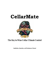
Ambient Temperature Factor
The cooling system has the ability to cool a wine cellar eciently to 55°F as long as the ambient temperature of the area to
which the unit is exhausting does not exceed 110°F. Therefore, you want the condensing unit to exhaust in a space which
will not exceed 110°F and will allow for proper dissipation of the heat exhausted by the condensing unit. Without proper
heat dissipation, the system will not have the capacity to keep the wine at a desirable 55°F.
Ventilation
The necessity of dissipating heat away from the condensing unit is critical to the unit’s performance and cannot be
overstated. As the system operates and cools, a greater amount of heat is generated on the condensing side of the
system. Adequate ventilation is required in order to dissipate heat away from the condensing unit. If ventilation is
inadequate, the exhaust will heat the area or room and adversely aect the system’s ability to cool. In some cases, it
may be advisable to install a vent fan to dissipate heat within the exhaust area on the condensing side of the system.
However, you must have a fresh air inlet as well.
Note: If you are unsure whether you have adequate ventilation in your installation location,
please contact us at suppor[email protected] or 1-800-343-9463.
WARNING! Allowing your system to operate in high ambient temperatures for
extended periods of time will greatly decrease the life of your system and void
your warranty. The cooler the temperature of the air entering the condenser coil,
the more cooling capacity the system has. The lower the heat gain through a
common wall, the lower the consumption of electricity.
BACK -
EXHAUST SIDE
FRONT - WINE CELLAR
Exterior cellar wall
Condensing unit

Page 12 | 1-800-343-9463
QS 020519
SYSTEM OPERATION
The cooling system is equipped with the hardware needed to support a 24-volt air conditioning thermostat (not included).
Initial Start-Up
Set the thermostat to COOL and fan switch to AUTO. Lower
the setpoint to the desired cellar temperature. (A temperature
of 55°F is the recommended setpoint.) See thermostat
instructions for details.
Normal System Cycle
The thermostat should turn the cooling system on when it
senses a temperature one (1) degree higher than the setpoint.
See thermostat instructions for details.
Anti-Short Cycle
Most thermostats have a safety feature that will prevent
the condensing unit from cycling on and o within a short
period of time. During the anti-short cycle, the condensing
unit will typically remain o for 5-7 minutes. See thermostat
instructions for details.
Fan Operation
If the fan switch on the thermostat is in the AUTO position, it
will run only during the cooling cycle. If the fan switch on the
thermostat is in the ON position, the fan will continuously run
until the switch is set back to the AUTO position.
Operation in Low Ambient Temperatures
The condensing unit comes equipped with a LAC (Low
Ambient Control). The LAC is a three-way modulating valve that
responds to discharge pressure. When the discharge pressure
falls below the valve’s dome pressure, the valve modulates
open to the discharge port which allows discharge gas to
bypass the condenser. Mixing the discharge gas with the liquid
creates high pressure at the condenser outlet, reducing the
ow and causing liquid to backup in the condenser. Flooding
the condenser reduces the area available for condensing.
This reduction in condenser surface area results in a rise in
condensing pressure during cold ambient conditions.
The condensing unit controller is preset at the factory. The
cut-in pressure is preset to 25psi and the cut-out pressure at
15psi. During low ambient temperatures (40°F or below), it will
be necessary to adjust the cut-in pressure to 10-15psi (15psi
is preferred) and the cut-out to 5psi to ensure compressor
startup. See page 13 for instructions on adjusting the cut-in
and cut-out pressures of the condensing unit.
NOTE: To ensure correct system operation, the 24V thermostat
must be placed inside the wine cellar, preferably in a central
location away from any airow.

www.whisperkool.com | Page 13
Quantum Series
Accessing Service Menu
Hold SERVICE for 3 seconds
Cycle through menu options – UP/DOWN
Press SET to see number of alarms
Press SET again to return to menu options
Exit menu - UP and SET
+
Accessing Alarm Code Information
Press and release ALARM
Cycle through menu options – UP/DOWN
Press SET to see number of alarms
Press SET again to return to menu options
Exit menu - UP and SET
+
Emerson
™
Electronic Unit Controller
Quick setup and troubleshooting guide
Low Pressure Cut-In Low Pressure Cut-Out
Alarm Description
PoF Keypad locked
Pon Keypad unlocked
P1 Suction probe failure
P2 Condenser probe failure
P3 DLT probe failure
HA High condenser temperature alarm
dLt DLT temperature alarm
dLL DLT lock alarm
HP High pressure trip alarm
HPL High pressure trip lock-out alarm
EE Module Failure
LOC Number of lock-outs
Code Description
StH CompressorStarts –1000 -999999
StL Compressor Starts –0 -999
CHH CompressorHours -1000 -999999
CHL Compressor Hours -0 -999
F1H Fan 1 Hours -1000 -999999
F1L Fan 1 Hours-0 -999
F2H Fan 2 Hours -1000 -999999
F2L Fand 2 Hours -0 -999
Example: If StH=12 and StL=500, the total num-
ber of compressor starts=12,500
Adjusting Low Pressure Settings
Hold DOWN and SET simultaneously for 3 seconds
to enter menu (PSI light will ash)
Cycle through menu options – UP/DOWN
Select function – SET
Adjust value – UP/DOWN
Store function - SET
Exit menu - UP and SET
+
+
Book of Alarms –
to enter alarm menu
Fan light 1 & 2
(Fan cycle units only)
Service – to enter
service menu
Service
menu
Run
time
Active
alarm
Alarm
history
Set – Displays
set point. In
programming
mode, it con rms
an operation
Compressor
Module Restart –
push to reset
the HPL, DLL
lock out faults
(cycle power)
When light is on, feature or component is on or active
For more information visit
EmersonClimate.com/ElectronicUnitController
or call 1-888-367-9950
Note: After 15 seconds of inactivity the controller will revert
to the default display.

Page 14 | 1-800-343-9463
QS 020519
Display Likely Causes Other Possible Causes
Controller display remains
blank after applying power
• Unit power not properly applied - check for proper applied voltage
• Power cable harness not plugged in properly or securely into the
back of the controller – check connections
• Power cable miswired – inspect cable, replace if
needed
• Electrical assembly miswired – trace wiring diagrams
Controller displays correctly,
but the green compressor
light is off and the
compressor is not running
• Jumper cable not plugged in properly or securely into the back of
the controller – check connections
• Controller is currently above the cut-in setting – check cut-in and
cut-out settings
• Jumper cable miswired – inspect cable, replace if
needed
Controller displays correctly
and the green compressor
light is on and the
compressor is not running
• Power cable harness not plugged in properly or securely into the
back of the controller – check connections
• Power cable not wired to the contactor or
compressor correctly, check wiring
• Power cable miswired – inspect cable, replace if
needed
Controller ashes “135” or
“P1”
• Current system pressure is above 135 PSIG – wait for system to
pull down
• Green harness not plugged in properly or securely into the back
of the controller – check connections
• Cable not connected properly with the pressure transducer –
check connections
• Transducer cable miswired – inspect cable, replace
if needed
• Damaged transducer – inspect transducer, replace
if needed
Controller ashes “P2” on a
unit with fan cycling
• Green harness not plugged in properly or securely into the back
of the controller – check connections
• Transducer cable miswired – inspect cable, replace
if needed
• Check condenser temperature sensor resistance
values against table in AE-1376, Section 8
Controller ashes “P2” on
a unit without fan cycling
after replacing a controller
• Controller not programmed properly – check parameters in the
advanced menu
Controller ashes “P3” on a
unit with DLT
• Jumper cable not plugged in properly or securely into the back of
the controller – check connections
• Jumper cable miswired – inspect cable, replace if
needed
• Faulty DLT temperature sensor – check the discharge
line temperature sensor resistance values against
table in AE-1376, Section 8
Controller ashes “P3” on
a unit without DLT after
replacing a controller
• Controller not programmed properly – check parameters in the
advanced menu
Fans not running on a fan
cycling unit and the fan
lights are not on
• Condensing temperature is currently below the fan cut-in
• Condensing temperature sensor not properly installed – check
installation
• Transducer cable miswired – inspect cable, replace
if needed
• Faulty temperature sensor - check condenser
temperature sensor resistance values against table in
AE-1376, Section 8
Fans not running on a fan
cycling unit and the fan
lights are on
• Power cable harness not plugged in properly or securely into the
back of the controller – check connections
• Power cable miswired – inspect cable, replace if
needed
• Electrical assembly miswired – trace wiring diagrams
Controller ashes “HP” at
power-up
• Jumper cable not plugged in properly or securely into the back of
the controller – check connections
• High pressure switch is seeing above the cut-out pressure
• For a replacing an -00 controller, ensure that the jumper cable is
the latest revision. It should have a blue wire in the harness. See
replacement instructions for more details
• Jumper cable miswired – inspect cable, replace if
needed
• Faulty xed Hp switch – inspect switch, replace if
needed
Controller ashes “HP” or
“HPL”
• System operation causing high discharge pressures, check
system operations
• Bad high pressure switch, verify system pressure
when the pressure switch trips.
• See AE-1376, Section 7.2 for more details
Controller ashes “DLT” or
“DLL”
• System operation causing high discharge line temperatures,
check system operations
• Faulty temperature sensor - check DLT sensor values
against table in section 8
• See AE-1376, Section 7.1 for more details
Controller ashing “HPL”
or “DLL”
• System operation causing high discharge pressures (HPL) or
high discharge line temperatures (DLL) repeatedly, check system
operations
• To clear an “HPL” or “DLL” lockout, you can hold the Restart
button for 3 seconds twice, or cycle power to the unit. If using
the reset button, the alarm condition will have to clear (DLT
temperature drops or Hp switch resets), and any minimum off
time will need to complete (5 minutes for the xed Hp switch)
EmersonClimate.com/ElectronicUnitController
2013ECT-46 (9/13) Emerson is a trademark of Emerson Electric Co. ©2013 Emerson Climate Technologies, Inc. All rights reserved.

www.whisperkool.com | Page 15
Quantum Series
Unit has ice forming on the evaporator
Possible cause Solution
There is something blocking the supply and/or return air Remove blockage
The evaporator fan is not turning on Call service tech to troubleshoot
If evaporator continues to ice Observe ice formation pattern. If only partway up the coil face,
the system could be low on refrigerant. If all the way up, the coil
may be dirty or airow is blocked.
The set point is too low
Raise set point to recommended temperature of 55°F.
Unit does not run/power up
Possible cause Solution
Evaporator is not plugged in Make sure the unit is plugged into an outlet
Line voltage rating is incorrect for the system Check voltage line to make sure there is 110V-120V
Room at set point Lower set point
Thermostat not calling for cooling Lower set point
Faulty thermostat or wiring Call Customer Service at 1-800-343-9463
Cellar temperature is too warm
Possible cause Solution
The temperature of the room to which the unit is exhausting has ex-
ceeded 110°F
Intake temperature needs to drop below 110°F
The system is undersized for the cellar Order correctly sized system
There is something blocking the supply and/or return air on the evapora-
tor or condenser side of the unit
Remove airow obstruction
Compressor is not turning on Please contact the installing technician to troubleshoot
Compressor keeps cycling on overload Make sure condenser fan is working and there is no airow
obstruction
Poor seal around door or other areas requiring a seal (around the unit
itself, wall joints, etc.)
Make sure there are no air gaps around the door. If door seal is
damaged, replace it.
Thermostat set too high Lower set point
Evaporator coil is frosted or iced up Observe ice formation pattern. If only partway up the coil face,
evaporator could be low on refrigerant. If so, contact the install-
ing technician to assist with troubleshooting.
System runs constantly
Possible cause Solution
Leaky door seal or poorly insulated cellar Fix leaky door seal and insulate cellar in accordance with this
manual (page 10)
WHISPERKOOL TROUBLESHOOTING GUIDE

Page 16 | 1-800-343-9463
QS 020519
Unit leaks water
Possible cause Solution
Evaporator unit is not level Evaporator unit should be level in ceiling to prevent leaking
Drain line clogged or kinked Check drain line to make sure water can ow freely
Drain is clogged, preventing water from escaping Remove ¾” CPVC caps on P-trap and check for blockage; if necessary,
use the supplied drain line brush to clean the P-trap
Drain line does not have a downward slope Fix drain line so there is a downward slope from the unit to the drain
Coil is iced, causing the drain pan to freeze and water to overow Melt ice with a blow drier and soak up with a towel
Unit runs but does not cool
Possible cause Solution
Lack of air ow Make sure fan is unobstructed; evaporator coil, and condenser coil are
clean and free of debris
System undersized Call Customer Service at 1-800-343-9463
Compressor is overheating Shut system o for an hour to allow compressor to cool. Turn back on
and check for cooler airow out. If compressor runs, check to see if
evaporator coil is dirty and if so, clean it. If problem persists, contact
your installing technician to assist with troubleshooting.
Evaporator fan runs but compressor does not
Possible cause Solution
Compressor and/or starting components faulty Contact installing technician to troubleshoot
System may be performing the WHM function Allow cooling system to revert back to cooling mode
Compressor may have overheated Shut system o for an hour to allow compressor to cool. Turn back on
and check for cooler airow out. If compressor runs, check to see if
evaporator coil is dirty and if so, clean it. If problem persists, contact
your installing technician to assist with troubleshooting.
Compressor runs but evaporator fan does not
Possible cause Solution
Faulty fan motor Contact installing technician to troubleshoot
Faulty thermostat Contact installing technician to troubleshoot
Compressor short cycles
Possible cause Solution
System low on refrigerant charge Contact installing technician to troubleshoot
Condensing fan motor/capacitor faulty Contact installing technician to troubleshoot
Compressor and/or starting components faulty Contact installing technician to troubleshoot
Humidity in cellar too low
Possible cause Solution
Not enough moisture Install humidier or decorative fountain in wine cellar

www.whisperkool.com | Page 17
Quantum Series
MAINTENANCE SCHEDULE
Monthly
1. Check for debris surrounding condensing unit (i.e. leaves, branches, trash, etc.); remove all
obstructions
2. Check for unusual noise or vibration
3. Check the drain line to see if it is above the waterline (if draining into a vessel)
Every Six
Weeks
Using the supplied drain line brush, clean the P-trap and drop a pan tab into the drip tray (see
the following page for more details).
Quarterly
1. Use a vacuum with brush attachment to clean the evaporator coil; be careful not to crush
coil ns when cleaning
2. Ensure the condensing unit is free of debris and dust
3. Have a certied HVAC technician service the condensing unit and clean the condenser coil
Annually
1. Inspect for corrosion
2. Check wiring connections and integrity of cords
3. Pour a 50/50 bleach solution into the drain line every spring
NOTE: For ducted systems, WhisperKOOL recommends lters with a mean eciency reporting value (MERV) of
4 or better. Filters are not included with the unit.

Page 18 | 1-800-343-9463
QS 020519
ADDING PAN TABS
Pan tabs kill bacteria and related odors, remove sludge and scale, and help to prevent water damage caused by con-
densate overow. They are non-corrosive and easy to install. Simply use any access panel to drop a pan tab into the
drip tray every six weeks.
WARNING: Keep pan tabs out of reach of children. They contain quaternary ammonium chloride
and can cause skin and eye irritation. They are harmful or fatal if ingested. Wear protective gloves
when handling pan tabs. Wash thoroughly after handling. If pan tabs make contact with eyes, rinse
cautiously with water for several minutes. In case of an emergency, call 1-800-255-3924 (24 hours).
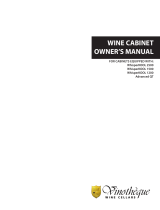
To clean the P-trap, remove the ¾” CPVC cap and run a drain line brush through the T-junction until all sludge and
slime is removed. If necessary, rotate T-junction for easier access. See illustration below for details.
1. REMOVE CAP
2. INSERT DRAIN LINE BRUSH FROM THIS END
CLEANING PTRAP
TO UNIT
Page is loading ...
Page is loading ...
Page is loading ...
Page is loading ...
Page is loading ...
Page is loading ...
Page is loading ...
-
 1
1
-
 2
2
-
 3
3
-
 4
4
-
 5
5
-
 6
6
-
 7
7
-
 8
8
-
 9
9
-
 10
10
-
 11
11
-
 12
12
-
 13
13
-
 14
14
-
 15
15
-
 16
16
-
 17
17
-
 18
18
-
 19
19
-
 20
20
-
 21
21
-
 22
22
-
 23
23
-
 24
24
-
 25
25
-
 26
26
-
 27
27


WhisperKool Quantum 9000 (24V Kit) Owner's manual
- Type
- Owner's manual
- This manual is also suitable for
Ask a question and I''ll find the answer in the document
Finding information in a document is now easier with AI
Related papers
-
WhisperKool Quantum 12000 Owner's manual
-
-
-
-
-
-
-
-
-
Other documents
-
 CellarPro 6200VSi Owner's manual
-
 Vinotheque 8000 User manual
-
 CellarPro 4200VSi Owner's manual
-
 CellarMate Wine Cellar Climate Control Specification
-
 N'Finity 3000 User manual
-
 Pride Mobility Interactive Assist Owner's manual
-
Wine Guardian SS018 Ductless Split System Wine Cellar Cooling Unit Owner's manual
-
 Vinotheque GCM-01 030110 User manual
-
Alpine 480-ECO-TBLK User guide
-
Quantum 27ACP2-407 User manual


