Page is loading ...

COMPLETE SYSTEM
Instruction Manual
Model #
VIS300-7M2
www.svat.com
SVAT ELECTRONICS
now you can see
SVAT ELECTRONICS
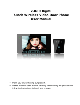
HANDS FREE 2-WIRE COLOR VIDEO INTERCOM SYSTEM
w/ 7" LCD Monitor and Night Vision Security Camera

TO REDUCE THE RISK OF ELECTRIC SHOCK, DO NOT REMOVE THE COVER (BACK).
NO USER SERVICEABLE PARTS INSIDE. REFER SERVICING TO QUALIFIED SERVICE PERSONNEL.
CAUTION
RISK OF ELECTRIC SHOCK, DO NOT OPEN MONITOR
VIS300 - 7M2 www.svat.com
PRODUCT WARRANTY INFORMATION
Please visit our website at www.svat.com
for information about your product’s warranty.
Phone: 1.866.946.7828 SVAT USA SVAT CANADA
Fax: 1.888.771.1701 60 Industrial Parkway 4080 Montrose Road
Website: www.svat.com USA 14227 Canada L2H 1J9
Warranty Terms
1. SVAT products are guaranteed for a period of one year from the date of purchase against defects in workmanship
and materials. This warranty is limited to the repair, replacement or refund of the purchase price at SVAT’s option.
2. This warranty becomes void if the product shows evidence of having been misused, mishandled or tampered with
contrary to the applicable instruction manual.
3. Routine cleaning, normal cosmetic and mechanical wear and tear are not covered under the terms of this warranty.
4. The warranty expressly provided for herein is the sole warranty provided in connection with the product itself and no
other warranty, expressed or implied is provided. SVAT assumes no responsibilities for any other claims
not specically mentioned in this warranty.
5. This warranty does not cover shipping costs, insurance, or any other incidental charges.
6. You MUST call SVAT before sending any product back for repair. You will be sent a Return Authorization form with
return instructions. When returning the product for warranty service, please pack it carefully in the original box with
all supplied accessories, and enclose your original receipt or copy, and a brief explanation of the problem
(include RA #).
7. This warranty is valid only in Canada and the continental U.S.
8. This warranty cannot be re-issued.
We take quality very seriously. This is why all of our products come with a one year warranty from the original purchase date
against defects in workmanship and materials. If you have warranty or support issues please contact us using any of the following
methods:

SVAT ELECTRONICS
now you can see
WHAT IS INCLUDED ....................................................................................................................2
IMPORTANT SAFETY PRECAUTIONS ............................................................................................3
FEATURES ..................................................................................................................................4
BUTTON FUNCTIONS AND CONNECTIONS ...................................................................................5
7" LCD MONITOR .....................................................................................................5
CAMERA/DOORBELL ................................................................................................5
WIRING INSTRUCTIONS ..............................................................................................................6
CONNECTION 1 ........................................................................................................6
CONNECTION 2 ........................................................................................................7
MONITOR INSTALLATION ............................................................................................................9
WALL MOUNTING ....................................................................................................9
TABLE MOUNT .........................................................................................................9
CAMERA INSTALLATION ...........................................................................................................10
ANGLED MOUNT ...................................................................................................10
FLAT SURFACE MOUNT ..........................................................................................11
BUTTON OPERATIONS ..............................................................................................................11
GENERAL INFORMATION ..........................................................................................................12
TROUBLESHOOTING .................................................................................................................12
SPECIFICATIONS .......................................................................................................................13
NOTES AREA ............................................................................................................................15
WHAT IS INCLUDED
1- 7" TFT- LCD Monitor 1 Indoor/Outdoor
Doorbell/ Camera
1- 50ft Cable
1 Power Adapter (for
Monitor)
2 Window Warning
Stickers
• MountingHardware
(Camera and Monitor)
• 2AngledCameraMounts
• 1YearWarranty
• InstructionManual
• 24/7LifetimeLive
Customer Service
TABLE OF CONTENTS
2

SVAT ELECTRONICS
now you can see
PLEASE READ BEFORE INSTALLING
• Whencleaning,useaDRY,lint-freecloth.Unplugthecamera,monitorandAC/DCadaptersbefore
cleaning. NEVER immerse any components in water and do not spray cleaners or solvents on the units.
Doing so may damage the units or cause electrical shock.
• Locatethecamera,monitorandAC/DCadapterswherethereisadequateventilation.Donotlocatethe
camera in direct sunlight.
• Donotlocatethecamera,monitorandAC/DCadaptersnearheatsourcessuchasheatregisters,radiators,
ovens, furnaces or other appliances with high operating temperatures.
• Donotusethecameranearwaterordampandwetenvironments,suchasabathtub,laundrytub,
kitchen sink, or wet basement.
• Donotusewithextensioncords.UseonlytheAC/DCadaptersprovidedwiththissystem.
***Note: Use of other adapters may damage the units and void your warranty.
• Keepthecamera,monitorandAC/DCadaptercordsoutofreachofchildren.
• Onlyplugcomponentsintostandardhouseholdvoltageoutlets(110VAC,or60Hz).
• DonotplacecordsfromtheAC/DCadapters,cameraormonitorwheretheycanbepinchedorstepped
on. Protect the cords by keeping them out of the way of children, pets and routine household trac.
• Donotplaceheavyobjectsonpowercordsorcovercordswithrugsorcarpet.
• UnplugtheAC/DCadaptersfromthewalloutletwhenthesystemisnotinuseforextendedperiodsof
more than a week; vacations etc...
• Mishandling,alterationsormodicationsnotapprovedbythemanufacturerwillvoidthewarranty.
THINGS TO CONSIDER BEFORE INSTALLATION
• Donotplacetheintercomsystemnearstrongmagneticelds,suchastelevisionsandvideorecorders.
• Donotplacethevideointercomsystemindirectsunlight.
• Donotdisassemblethisdevicefreely;therearehighvoltageowsinsidethesystemthatcancause
bodily harm.
CAUTION!
• Do not paint over the camera.
• Connect this unit ONLY to other compatible units. Do not connect it to any other type of alarm or auxiliary
device. Connecting anything else to this unit may damage it or prevent it from operating properly.
• If connecting device to a doorstrike please make sure it has a 8-16 VAC power supply, or it will not be
compatible with this device
VENTILATION
Slots and openings in the monitor and the back or bottom are provided for ventilation and to ensure reliable
operation of the video monitor or equipment and to protect if from overheating. These openings must not be
blocked or covered. The openings should never be blocked by placing the video monitor on a bed, sofa, rug, or
other similar surface. Video monitor should never be placed near or over a radiator or heat register. Video monitor
should not be Placed in a built-in installation such as a bookcase unless proper ventilation is provided.
IMPORTANT SAFETY PRECAUTIONS
3

SVAT ELECTRONICS
now you can see
Fast & Hassle-Free Setup
SVAT's video intercom system is incredibly easy to set up and use. It can work with your existing door bell wiring,
so you can connect everything yourself within minutes (50ft cable included).
See and Hear Everything with Audio & Video
Enjoythesafetyofmonitoringyourentranceandbeingabletocarryonconversationswithouteverhavingtoopen
the door to strangers. If you hear a suspicious noise or are curious to see what is happening outside, you can simply
press the view button and instantly monitor your entranceway.
Hands Free Operation
When a visitor arrives and presses the doorbell button, your monitor will sound a chime and display your visitor
on-screen. Safely and conveniently know who is at your door without having to physically check.
24 Hour Protection with Night Vision
Six infrared (IR) LEDS let you see in the dark, up to 8ft
1
away! They activate automatically when it gets dark, and
deactivate during the day to save energy (CDS sensor). Day or night, you'll have a clear view of your entrance.
Unlock Your Door with the Touch of a Button
Connect the system to an electric door strike
2
and you will be able to open the door remotely by pressing the
unlock button on the monitor.
Flexible Mounting Options
The 7” LCD monitor has a contemporary design and can be wall mounted or placed on a table with the built-in
stand(upto50ftawayfromthedoor).Usetheincludedangledmounttoadjustthecamerasothatyouhavea
comprehensive view of your visitor.
8 Dierent Chimes
The VIS300-7M2 features a variety of standard chimes as well as dierent melodies for holidays, patriotic events
and special occasions.
24/7 Lifetime Live Customer Support
Assistance is available whenever you need it. Our customer support team can be reached by phone 24/7, or by
e-mail and live web chat services so that you will always have access to an expert.
Notes:
1 The Infrared LEDs need to reect o of an object in order for the camera to display an image. If there is no object within range of the LEDs
(ex. Camera is pointing into an open eld) there will be nothing displayed on the camera.
2. Door Strike is NOT included.
IMPORTANT!
Wall mounting should follow the manufacturer's instruction, and should use the included mounting kit or a
mounting kit approved by the manufacturer. Do not place video monitor or equipment on an unstable stand or
table.Thevideomonitororequipmentmayfallcausinginjurytoachildoradult,anddamagetotheequipment.
FEATURES
4

SVAT ELECTRONICS
now you can see
7" LCD Monitor
1. Microphone
2. Power Supply Indicator LED
3. 7"LCD Screen
4. Speakers
5. View – Allows you to monitor the camera
6. Unlock – Releases door strike
7. Talk – Initiates communication with camera
unit (from monitoring mode)
8. Melody – Changes door bell melody (must be
in monitoring mode)
9. MelodyVolume–Adjustthemelodyvolume
level between low (L), medium (M), and high (H)
10. Volume – Controls the speaker volume
on the monitor
11. Chroma – Controls color of image
12. Brightness – Controls brightness
of image
13. Camera Connection (positive =1 and
negative= 2)
14. Door Strike Connection (positive = 3 and
negative = 4)
15. Wall Mount Connection
16. Ventilation Ports
17. Stand (Optional Use)
18. Mount
BUTTONS AND CONNECTIONS
Camera/Doorbell
1. CDS sensor – Detects level of darkness to
automatically activate IR LEDs
2. Camera
3. Microphone
4. Infrared (IR) LEDs – Allow for night vision
up to 8 ft
5. Mounting Screw Hole
6. Speaker
7. Door bell
8. Camera to Monitor Connections (positive =
1 and negative = 2)
9. Door Strike (positive = 3 and negative = 4)
10. Mounting Bracket
5

SVAT ELECTRONICS
now you can see
WIRING INSTRUCTIONS
Connecting the Camera – Note: You will need a philips head screwdriver
• Loosenthescrewtothecamera’spositiveconnection(marked1)by
turning the screw counter clockwise.
Note: Do not fully unscrew the screw, just loosen it
enough to t the horseshow end of the 50ft wires.
• SlidetheHorseshoeendoftheBLUEwire(marked1)
underneath the Screw Terminal on the camera’s positive
connection (connection 1).
• Tightenupthescrewtolockthebluewireintoplace.
• Loosenthescrewtothecamerasnegativeconnection
(marked 2) by turning the screw counter clockwise.
Note: Do not fully unscrew the screw, just loosen it
enough to t the horseshow end of the 50ft wires.
• SlidetheHorseshoeendoftheBrownwire(marked2)
underneath the Screw Terminal on the camera’s negative
connection (marked 2).
• Tightenupthescrewtolockthebrownwireintoplace.
Connection 1 (Recommended)
Connecting the Monitor to Camera - Note: You will need a small
at head screwdriver
• Usingascrewdriverorsimilarobjectpushdownonthesmall
grey box above the hole marked as 1.
• Insert the available end of the blue wire into the monitor’s
positive camera connection (marked 1) and make sure it is
completely inserted.
• Release the downwards pressure on the grey box and this
should lock the wire into place.
6

SVAT ELECTRONICS
now you can see
Connecting the electric Doorstrike to Monitor (Doorstrike and Wiring not Included)
The VIS300-7M2 does not come with an electric door strike (lock), if you would like to connect a door strike. The
door strike must run o a 8-16 VAC power supply to be compatible with the VIS300-7M2.
If the two wires are not already connected to your doorstrike:
• Usingtheinstructionmanualprovidedwithyourdoorstrike,connectthepositiveandnegativewirestotheir
proper terminals on the doorstrike.
Connecting Doorstrike to Monitor
• Usingascrewdriverorsimilarobjectpushdownonthesmallgreyboxabovethedoorstrikepositiveconnec-
tion hole marked as 3.
• Insertthepositivewirefromthedoorstrikeintothepositivedoorstrikeconnectiononthemonitor(marked
3) and make sure it is completely inserted.
• Releasethedownwardspressureonthegreyboxandthisshouldlockthewireintoplace.
• Pulllightlyonthewiretomakesureitissecure.
• Repeattheabovestepsforthenegativewireandnegativeconnectionmarked4.
Your door strike should now be connected to the monitor.
Note: Connecting the VIS300-7M2 to an electronic door strike (lock) is optional and is not required
for operation.
Connection 2
WIRING INSTRUCTIONS CONT....
• Repeat the above steps using the brown wire and the monitor’s negative camera connection (marked 2)
• Test that the wires are properly connected by lightly attempting to pull the wires away from the monitor.
They should not come disconnected.
Your camera and monitor should now be connected .
7

SVAT ELECTRONICS
now you can see
Connecting the Monitor to Camera - Note: You will need a small athead screwdriver
• Usingtheotherendofthe50footwiringprovidedinserttheendofthebluewireintothemonitor’s
positive camera connection (marked 1) and hold it there.
• Usingthescrewdriverpushdownonthesmallboxabovetheholethewireisinsertedinto,thisshouldlock
the wire into place.
• Sameendoftheprovidedwireinserttheendofthebrownwireintothemonitor’snegativecamera
connection (marked 2) and hold it there.
• Usingthescrewdriverpushdownonthesmallboxabovetheholethewireisinsertedinto,thisshouldlock
the wire into place.
• Youcameraandmonitorshouldnowbeconnected.
If the two wires are not already connected to your doorstrike:
• Usingtheinstructionmanualprovidedwithyourdoorstrike,connectthepositiveandnegativewiresto
their proper terminals on the doorstrike.
Connecting electric doorstrike to Camera
• Usingtheinstructionguideprovidedwithyourdoorstrike,insertthepositiveandnegativewires(not
included) into their proper place on the doorstrike.
• Loosenthescrewtothecamera’sdoorstrikepositiveconnection(marked4)byturningthescrewcounter
clockwise.
Note: Do not fully unscrew the screw, just loosen it enough to t the horseshow end of the wires.
• SlidetheHorseshoeendofthedoorstrikespositivewireunderneaththeScrewTerminalonthecamera’s
positive connection (connection 4).
• Tightenupthescrewtolockthewireintoplace.
• Loosenthescrewtothecamera’sdoorstrikenegativeconnection(marked3)byturningthescrewcounter
clockwise.
Note: Do not fully unscrew the screw, just loosen it enough to t the horseshow end of the wires.
• SlidetheHorseshoeendofthedoorstrikesnegativewireunderneaththeScrewTerminalonthecamera’s
negative connection (connection 3).
• Tightenupthescrewtolockthewireintoplace.
• Your door strike should now be connected to the camera.
Note: When using this connection keep in mind that the door strike will be connected to the camera,
which is outside of your house – if the camera gets disconnected the electric door strike will get
disconnected as well.
WIRING INSTRUCTIONS CONT....
Connecting the Camera – Note: You will need a philips head screwdriver
• Unscrewthescrewfromthecamera’spositiveconnection(marked1).
Note: Do not fully unscrew the screw, just loosen it enough to t the horseshow end of the
50ft wires.
• Usingthe50ftwiringprovidedslidethebluewirewiththescrewMountontheendunderneaththescrew
to the Camera’s positive connection (marked 1).
• Screwthescrewbackintoplace,lockingthebluewireunderneaththepowerinput.
• Unscrewthescrewfromthecamera’snegativeconnection(marked2)
Note: Do not fully unscrew the screw, just loosen it enough to t the horseshow end of the
50ft wires.
• Usingthesamesideofthe50ftwireprovided,slidethebrownwirewiththescrew.Mountontheend
underneath the screw to the camera’s negative connection (marked 2).
• Screwthescrewbackintoplace,lockingthebrownwireinthecameraoutput.
8

SVAT ELECTRONICS
now you can see
3. Plug the other end of the power adapter into
a power source. (It is recommended to use a surge
protecting power bar or a UPS.
4. Once the bracket is properly mounted, there are
four slots on the back of the monitor that will t
easily into the mount. Line up the slots with the
pegs on the monitor and slide monitor down-
wards. This will securely lock the monitor into the
mounting bracket.
Table Mount
1. Themonitorisalsoabletostanduprightonaat
surface using the table stand on the back of the
monitor.
2. Placemonitoronaatlevelsurface.
- Make sure that the at surface is close to a
power source so it can be plugged in.
3. Pull the bottom side of the stand away from the
monitor.
4. Plugthejackofthepoweradapterintothebackof
the monitor (labeled AC15V).
5. Plug the other end of the power cable into power
source.
MONITOR INSTALLATION AND OPERATION
WALL MOUNTING
1. Locate a desired mounting location for the
camera/ doorbell station and fasten the mount
using the included mounting hardware.
- Make sure the mounting location is at an
appropriate level for you to access the but
tons and easily view the LCD screen and is
close enough to a power source to be
plugged in .
2. Plugthejackofthepoweradapterintotheback
of the monitor (labeled AC15V).
9

SVAT ELECTRONICS
now you can see
Complete all wiring before mounting the camera.
Angled Camera Mount – Must be Mounted BEFORE Flat Mount
The VIS300-7M2 has two identical angled mounts included with it so that you can place your camera on a twenty
degree angle or a 40 degree angle. This will make the camera angled towards the door instead of straight ahead.
This may or may not be necessary for your application.
If using one angled mount: (twenty degrees)
1. Lift up sticker located on the front of the camera on right side.
2. Completelyremovethescrewfromtheatcameramount.
3. Removecamerafromatmount(itisheldinbyplastictabs,youmayhavetoapplysomeforcetoseparate
the two pieces).
4. Locate a desired mounting location.
5. Pull wiring through the center hole on the angled mount.
6. Screw the angled mount into desired area near front entrance.
7. Screwtheatmountontotheangledmountbyusingthetwoprotrudingscrewholeslocatedontheangled
mount.
8. Reconnect the wires to the proper terminals (instructions above) and tighten the securing screws to secure
the wires to the back of the camera.
9. Put camera into the mount and insert the screw into the hole behind the sticker, tighten the screw to secure
camera to the mount.
10. Peel the paper o the back of the rest of the sticker in front and secure it over the screw hole.
If using two angled mounts: (40 degrees)
1. Lift up sticker located on the front of the camera on right side.
2. Completelyremovethescrewfromtheatsurfacemount.
3. Removecamerafromatsurfacemount(itisheldinbyplastictabs,youmayhavetoapplysomeforceto
separate the two pieces).
4. Locate a desired mounting location.
5. Pull wiring through the center hole on the angled mount.
6. Screw the angled mount into desired area near front entrance.
7. Place second angled mount over the rst angled mount with the open area facing outwards. (in same
direction as the rst angled mount).
8. Pull the wiring through the center hole of the second mount.
9. Secure the two mounts together by screwing a screw through the small holes located on the bottom and
top of the second mount.
10. Screwtheatmountontotheangledmountbyusingthetwoprotrudingscrewholeslocatedonthe
angled mount.
11. Reconnect the wires to the proper terminals (instructions above) and tighten the securing screws to secure
the wires to the back of the camera.
12. Put camera into the mount and insert the screw into the hole behind the sticker, tighten the screw to secure
camera to the mount.
13. Peel the paper o the back of the rest of the sticker in front and secure it over the screw hole.
Make sure camera is at the average face level (145 cm – 160 cm from ground
CAMERA INSTALLATION AND OPERATION
10

SVAT ELECTRONICS
now you can see
Flat surface mount
1. Lift up sticker located on the front of the camera on right side.
2. Completelyremovethescrewfromtheatsurfacemount.
3. Remove camera from mount (it is held in by plastic tabs, you may have to apply some force to separate the
two pieces)
4. Locate a desired mounting location.
5. Screw mount onto desired area near front entrance by the holes on the top and bottom of mount.
6. Reconnect the wires to the proper terminals (instructions above) and tighten the securing screws to secure
the wires to the back of the camera.
7. Put camera into the mount and insert the screw into the hole behind the sticker, tighten the screw to secure
camera to the mount.
8. Peel the paper o the back of the rest of the sticker in front and secure it over the screw hole.
CAMERA INSTALLATION AND OPERATION CONT...
BUTTON OPERATIONS
Monitor - Front - From Left to Right
View: Allows you to view and hear outside without someone pressing the doorbell. This will display the
image from the camera as well as allow you to hear what the camera’s audio picks up outside.
Unlock: If the camera or monitor is connected to an electric door strike, you can trigger the door strike by press
ing the unlock button. The door strike will remain triggered as long as you are pushing the unlock
button down. (Electric door strike is not included).
Talk: When someone presses the doorbell button on the camera or the monitor is in view mode, the hands
free 2-way audio communication can be initiated by pressing and releasing the talk button. To hang
up, press the talk button again.
Monitor - Side - From Left to Right
Melody: There are 8 dierent options for melodies to choose from. To change each
melody you must be in monitoring/view mode. While in view mode, press
the melody button to switch between the available melodies. Keep pressing
the melody button until the desired melody is played.
L M H (Low, Medium, High): This switch controls the volume level of your melody. Setting the switch on ‘L’
will make the melody volume low, on ‘M’ will make the melody volume
medium and on ‘H’ will make the melody volume high.
Volume: This volume knob controls the volume on monitor when listening to the
outside audio. THE VOLUME ON THE CAMERA (OUTSIDE) CANNOT BE ADJUSTED.
11

SVAT ELECTRONICS
now you can see
Chroma: AdjustingtheChromaknobwillallowyoutoadjusttheintensityofthecolorin
thepictureonthemonitor.Thehigheryouadjust,themoreintensethecolorwillbe.
Brightness: Adjustingthebrightnesswillmakethepicturebrighterordarkeronthemonitor.The
brighteritiswhereyourcamerais,theloweryoushouldadjustthebrightness.
1. To operate the camera, press and release the doorbell button on the camera.
2. The chime will ring on the inside monitor and the monitor screen will display the audio and video from
the camera.
3. To communicate from the monitor to the camera press and release the “Talk” button. Note: Audio from the
monitor will not be heard on the camera until the “Talk” button is pressed on the monitor.
4. Press and hold the “Unlock” button to trigger the electric doorstrike (IF INSTALLED) and allow the visitor to
enter. (A 12 V AC compatible electric door strike (not included) must be properly connected).
Automatic Monitor Time Out
The monitor will automatically stop displaying the audio/video at set intervals depending on the situation.
- If the doorbell is pressed and no other buttons are pressed the monitor will shut o after 55 seconds.
- If the view button is pressed the monitor will shut o after 40 seconds.
- If in view mode and the “Talk” button is pressed the communication and the monitor will stay on for
120 seconds.
GENERAL INFORMATION
12
BUTTON OPERATIONS CONT....
No Picture/Signal • Makesurealltheconnectionsaresecureandproperlyconnected
• Makesureyourmonitorispluggedintoapowersourcefromthe
AC15V adapter on the back of the monitor
• Makesurethereisnothingobstructingtheviewofthecamera
Note: that the camera will not appear on screen until someone
presses the doorbell or you press the view button yourself.
Picture to Bright/Dark • Thenightvisioncomesonautomaticallywhenthelightlevels
drop; try the camera in a pitch black setting. The area that the
camera is in may get too much light to activate the sensor.
No Audio • Makesurethevolumenotchonthemonitoristurnedupandthat
nothing is interfering with the speakers or microphone on the
monitor, or the camera
• Ifthemelodyisnotplaying,makesurenothingisinterferingwith
thespeakerandtryadjustingthemelodyvolumetoa
higher level
• Makesurewhateveryouaretryingtoheariscloseenoughtothe
microphone on the camera/doorbell device
• Disconnectandreconnectthewiresfromthecameraandthe
monitor to make sure they are secure.
TROUBLESHOOTING

SVAT ELECTRONICS
now you can see
Door Strike not Functioning • Doornotunlocking–Makesureyouhaveitwiredtoanelectric
door strike that will operate with 15 VAC (doorstrike NOT included)
• Makesurethatalltheconnectionsaresecureand
properly connected
No one can hear me outside but I
can hear them
• Makesurealltheconnectionsaresetupproperlyandsecurely
• Makesureyouarenotpressingthe‘View’button;theviewbutton
allows you to see and hear outside but prevents the outside from
hearing you. The talk button allows two way communication
Night Vision not Working • Thenightvisioncomesonautomaticallywhenthelightlevels
drop; try the camera in a pitch black setting. The area that the
camera is in may get too much light to activate the sensor
TROUBLESHOOTING CONT...
13
SPECIFICATIONS
CAMERA
Image sensor 1/3" color CMOS
Outdoor use yes
IP Rating IP44
Resolution 380 TV Lines
Night Vision Yes
Number of IR LEDs and
Range
6 LEDS, up to 8ft
IR LED control Automatic
Min. Illumination 2 Lux
Viewing Angle 58
TV System NTSC
Focal Length 6mm
Focus Type Fixed focus
Microphone yes
Motion Detection no
Audio Activation no
Sun Shield no
Housing Material ABS plastic
Housing Color Silver
Electronic shutter speed 1/60~1/15000 sec
Signal/Noise Ratio >40db
Power LED Indicator no
Camera Bracket yes
Operating temperature -20 C to 50 C
Dimensions 4.1” x 7.5” x 2.1”
Weight 0.5 LBS
Alarm/Siren Decibel no
VerticalAdjustment
no
HorizontalAdjustment With Included 20 degree
angled mounts
Max. Wiring Distance 164 ft (50ft included)

SVAT ELECTRONICS
now you can see
SPECIFICATIONS CONT...
14
Operating Humidity <80%
Dimensions (with
stand)
6.5” x 3.9” x 0.3”
Weight (with stand) 1. 25 Lbs
Door Strike Compatable Yes. Electric Door Strike
15 V
Door Strike power
output
15 V for duration of
button press
Maximum amount of
cameras
1
LCD MONITOR
Display 7" TFT LCD
Resolution 1440 x 86.58 mm
Source of Light No
Video Inputs 1x3.5mmjack(RCAto
3.5mm wire provided)
LCD Prole Ratio 16:09
Contrast Ratio 200:1
Brightness 250cd/m2
Response Time(ms) Tr:15ms/Tf:35ms
Viewing Angle 92
On/O Timer Yes
Sleep Timer No
AdjustableScreen
Settings
Brightness, chroma
Speaker Wattage 0.5W x 2
LED Indicators power
Housing Material plastic
Housing Color Silver and Grey
Power Input AC110 - 240V/50/60 Hz
Working current 15V 1200mA
Power consumption
(standby)
standby state <0.5W
Power Consumption
(camera on)
Work State<10W
Operating Temperature -10 C to 40 C
Operating Humidity 10% ~ 90%
Monitor Mount yes
Remote Control no

SVAT ELECTRONICS
now you can see
NOTES AREA
15

SVAT ELECTRONICS
now you can see
NOTES AREA
16

SVAT ELECTRONICS
now you can see
www.svat.com
Disclaimer
SVAT does not endorse any of SVAT products for any illegal activities. SVAT
is not responsible or liable in any way shape or form for any damage,
vandalism, theft or any other action that may occur while a SVAT product
is in use by the purchaser.
Instruction Manual
Model #
VIS300 - 7M2
www.svat.com
/