Page is loading ...

MULE 610 4×4
MULE 600
Utility Vehicle
Assembly & Preparation
Manual


Foreword
In order to ship Kawasaki vehicles as effi-
ciently as possible, they are partially disassem-
bled before crating. Since some of the most
commonly removed parts have a direct bear-
ing on a vehicle’s reliability and safety, consci-
entious pre-sale assembly and preparation be-
comes extremely important. Good setup pro-
cedures can prevent needless warranty claims
and give customers a greater sense of c onfi-
dence in Kawasaki and their Kawasaki Dealers.
This Assembly and Preparation Manual ex-
plains step by step procedures of the following
items for all Kawasaki utility vehicles.
1. Crate Handling
2. Uncrating
3. Assembly
4. Preparation
The selling dealer assumes sole responsibil-
ity for any unauthorized modifications prior to
sale. Refer to your Service Binder for any Ser-
vice Bulletins specifying Factory Directed Mod-
ifications (Special Claims) which must be per-
formed before the vehicle is ready for sale.
Whenever you see the following symbols
heed their instructions! Always follow safe
operating and maintenance practices.
WARNING
This warning symbol identifies special
instructions or procedures which, if not
correctly followed, could result in per-
sonal injury, or less of life.
CAUTION
This caution symbol identifies special
instructions or procedures which, if not
correctly followed, could result in dam-
age to, or destruction of equipment.
NOTE
○This note symbol indicates points of particular
interest for m ore efficient and convenient op-
eration.
Kawasaki Heavy Industries, Ltd. accepts no
liability for any inaccuracies or omissions in this
publication, although every possible m easure
has been taken to make it as complete and ac-
curate as possible. All procedures and specifi-
cations subject to change without notice.
© 2004 Kawasaki Heavy Industries, Ltd. Oct. 2004 (K)

Table of Contents
Cr
ate Handling..............................................................................
3
Crate Handling Precautions ........................................................ 3
Uncrating ...................................................................................... 3
Op
ening Crate .............................................................................
3
Parts C heck ................................................................................. 8
Assembly ...................................................................................... 10
S
teering Wheel............................................................................
1
0
Rear Bar ...................................................................................... 11
Front Bar ..................................................................................... 12
F
rench Labels for Canadian Models (KAF400A/B) .....................
1
3
Cargo Bed ................................................................................... 14
Preparation ................................................................................... 14
Battery Service ............................................................................ 14
Transmission Oil.......................................................................... 17
Front Final Gear Case Oil (KAF400A/C) ..................................... 17
Brake Fluid .................................................................................. 18
Brake Pedal................................................................................. 19
Parking Brake Lever .................................................................... 20
Steering Wheel............................................................................ 20
Tire Air Pressure.......................................................................... 20
Fuel ............................................................................................. 21
Engine Oil.................................................................................... 22
Throttle Pedal .............................................................................. 24
Choke Knob................................................................................. 25
Idle Speed Adjustment ................................................................ 25
Brake Light Switch....................................................................... 27
Headlight Beam........................................................................... 27
Wheel Alignment ......................................................................... 27
Fastener Check ........................................................................... 30
Standard Torque Table ................................................................ 32
Test Ride ..................................................................................... 32
A & P Check List ......................................................................... 32

UNCRATI
NG 3
Crate Handling
Crate Handling Precautions
Crate Position:
Always place the crate upright on its base.
The crate has been designed to carry the w eight
of the vehicle only in that position. The sides
and top of the crate are not strong enough to
act as the base of the crate. If the crate is tilted
very far or set on its end or side, loose parts
may be dislodged and fall inside the crate.
Mov
ing Crated Vehicle:
WARNING
Do n
ot move or lift the crate by pulling
on the crate bands. They are designed
to keep the cardboard cover on, and if
us
ed as handles they can snap, causing
you or the crate to fall unexpectedly.
Whenever moving the crate from one place to
another, use a fork lift or flat bed hand truck. Ve-
hicle crates are too big and heavy to be moved
by hand. While moving a crate, never stand it
on end or tip it over on its side. DO NOT DROP
crated vehicles.
Loading and Unloading Trucks:
To load or unload crates, use a fork lift, a lift
-type tail gate, or a ramp. Never unload crates
by hand. NEVER DROP crates off a truck.
Tyin
gDownCrates:
Always tie down crates when transporting
them. Put the tie downs across the crate at the
crat
e’s internal vertical braces. Do not use any
hooks on the crate.
Stacking Crates:
The number of crates that may be stacked on
top of one another depends on the condition of
the crates more than any other single factor.
Also, take into consideration the weight of the
upper crate(s), the sizes of all the crates in a
stack, and the strength of the bottom crate(s)
base on the type of crate construction (steel,
wood, bracing, etc.).
In any case, do not stack crates more than two
high for trucking, and three high for storage.
Uncrating
Opening Crate
•
Clear a space about 6 m (20 ft.) square to
give yourself plenty of space to work.
•
Place the crate upright on its base.
•
Remove the outer cover and inspect the unit
for concealed damage. If concealed damage
is evident, document the damage as outlined
in the Kawasaki Warranty Policies and Pro-
cedures Manual before proceeding to uncrate
the unit.

4 UNCRAT
ING
Top Panel Removal
•
Remove the screws from the crate brackets
on the top crate.
A. C
rate Screws
B. Top Crate
•
Using a BPS3 square drive bit (ex. IM-
PORT APEX Square Recess “Power Bits-
1/4 Hex-size #3” or MAGNA “Insert Bits-size
#3” with quick change holder), remove the
screws from the sides and ends into the top.
A. “Power Bit (APEX)”
WARNING
Be careful of staples and other sharp
fasteners. Remove or bend over all nails
in the crate base to prevent injure.
•
There are two screws in every corner.
•
Remove two screws in every cross member.
•
Top panel can be lifted from the unit. Have
ase
cond person help to remove t his piece
as it can be awkward to handle. Discard this
assembly. Take care when letting the rear bar
ass
embly down from the top, it is heavy and
may fall.
Side Panel Removal
•
Remove the (16) screws shown below. The
panel should come loose without excess
force; check for any screws missed if the
panel will not come off easily.
NOTE
○Trying to break the panels off can result in
da
mage to the unit.
•
Repeat procedure for the other side of the
unit. Discard these panels.
End Panel Removal
•
Remove the (5) screws shown below. The
panel should come loose without excess
force, check for any screws missed if panel
will not come off easily.
NOTE
○Trying to break the panels off can result in
damage to the unit.

UNCRATI
NG 5
•
Rep
eat as above for the rear panel. Discard
these panels.
Front Tie-down Removal
•
Remove front tie-downs by opening fully and
disengaging latch. Take care to undo these
evenly as there is heavy tension in the tie
-down.
A. Tie-downs (Front)
NOTE
○It is important to remove the top panel as the
unit will rise when the tie-downs are undone.
Failure to do so will result in damage to the
unit.
Rear Tie-down Removal
•
Remove rear tie-downs by opening fully and
disengaging latch. Take care to undo these
evenly as there is heavy tension in the tie
-down.
A. Tie-downs (Rear)
NOTE
○It is important to remove the top panel as the
unit will rise when the tie-downs are undone.
Failure to do so will result in damage to the
unit.
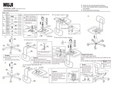
Removing The Bars From The Unit
•
Cut the tie bands that retain the steering
wheel and remove.
•
Remove the strap that holds the front bar and
rear bar assembly together.
A. Strap
B. Front Bar
C. Steering Wheel
•
Remove the rear bar assembly from the unit.
Have a second person help to remove this
piece as it can be awkward to handle. Take
care when letting the rear bar assembly down
from the unit, it is heavy and may fall.
•
Remove the crate bolts on floor of crate base.
•
Remove the bolts, nuts, and washers. Dis-
card them.
•
Remove the front bar from the unit.

6 UNCRAT
ING
A. Crate Bracket
B. Bolt
C. Fr
ont Bar (Right)
D. Nut, Bolt, and Washer

UNCRATI
NG 7
Dummy Page

8 UNCRAT
ING
Parts Check
NOTE
○There may be minor differences in appearance between these illustrations and the actual vehicle
parts.
•
Remove the parts and check the crate base and packaging materials carefully for loose parts. Check
the parts against the illustration. Order any parts that are missing from the crate. Part numbers are
provided in the following charts.
In the following charts under Remarks, D = diameter in millimeters, and L = length in millimeters.

UNCRATI
NG 9
No. Part Name
Qty
Remarks Part Number
1
Steering Wheel
1 46003-1265
Spring Washer (1) 461F1200
Nut, Steering Wheel (1) 92210-1249
Cover, Steering Wheel 1 14024-1574
2 Front Bar with 1 55047-0006
Bolt, Upper (2) D = 10, L = 70 92001-1618
Nut, Upper (2) D=10 92210-1204
Flat Washer (4) D=12 92022-1396
Bolt, Lower 4 D = 14, L = 36 92153-1282
3 Rear Bar with 1 55047-0008
Bolt, Lower, Rear Bar (2) D = 10, L = 20 130J1020
Nut, Lower, Rear Bar (2) D=10 92210-1204
Bolt, Lower, Rear Bar (4) D = 10, L = 16 130J1016
Screen (1) 14037-0035
Bolt
, Screen
(5)
D = 8, L = 20 130J0820
Nut, Screen (5)
D=8 92210-0005
Guard, Screen (1) 13271-0560
Seat Assy, Back (1) 53066-0078
Nut, Seat Assy, Back (4) D=8 92210-0005
Seat Belt (2) 53061-1012
4
Fre
nch Labels and Instruction for
KAF400A Canadian Models only
Instruction, Label 1 56030-0087
Label, Cargo Bed Information 1 56053-0066
Label, Tire/Max. Load 1 56053-0067
Label, Warning, Cargo Bed 1 56070-0054
La
bel, Warning, Off Highway Utility
Vehicle
1 56070-0055
Label, Warning, Refueling 1 56070-0057
L
abel, Warning, General
1 56070-1206
Label, Warning, Hot Surfaces
1 56070-1234
5
French Labels and Instruction for
K
AF400B Canadian Models only
Instruction, Label 1 56030-0090
Label, Cargo Bed Information 1 56053-0066
Label, Tire/Max. Load 1 56053-0105
Label, Warning, Cargo Bed
1 56070-0054
Label, Warning, Off Highway Utility
Vehicle
1 56070-0055
Label, Warning, Refueling
1 56070-0057
Label, Warning, General 1 56070-1206
Label, Warning, Hot Surfaces 1 56070-1234
6 Battery Vent Hose 1 L = 229 92190-1261
7 Owner’s Manual 1 –

10 ASSEM
BLY
Assembly
Steering Wheel
•
Remove the engine emission related hangtag
(Index
Card: P/No. 49007-2085) for Califor-
nia from the steering shaft.
A. S
teering Shaft
B. Hangtag
•
Hang it to the shift lever.
A. Shift Lever
B. Hangtag
NOTE
○This hangtag is not to be removed before sale.
Steering Wheel Installation
•
Remove the steering wheel nut (D = 12) and
the spring washer. Do not remove the black
washer (D = 45).
•
Set the front wheels s traight ahead.
A. Nut (D = 12)
B. Spring Washer
C. Steering Shaft
D. Black Washer (D = 45)
•
Mount the steering wheel on the steering
shaft so that it is straight ahead, and install
the spring washer and plated nut (D = 12).
•
Tighten the steering wheel nut to the specified
torque.
Torque : 54 N·m (5.5 kgf·m, 40 ft·lb)
A. Nut
B. Spring Washer
C. Cover
•
Install the steering wheel cover on the steer-
ing wheel by fitting the projections of the cover
into the notches of the wheel.

ASSEMBL
Y11
A. Cover
CAUTION
Be careful not to puncture a tire with
sharp fasteners. Remove or bend over
all nails in the crate base to prevent in-
jury.
•
Roll off the vehicle from the crate base.
•
Discard the crate base.
Rear Bar
Rear Bar Installation
•
Loosen the four mounting bolts (D = 8, L = 20)
and nuts to remove the crate brackets from
the screen.
A. Crate Bracket(s)
B. Bolt (D = 8, L = 20)
C. Nut
•
Discard the brackets, and reinstall the screen
on the rear bar with the bolts (4) and nuts
removed.
A. Bolts (D = 8, L = 20)
B. Screen
C. Nuts
•
Remove the two mounting bolts (D = 10, L =
20) and nuts from the lower end of the rear
bar.
A. Rear Bar
B. Bolt
C. Nut
•
Lift the seat up, and release the cargo bed
latch.
•
Lift the cargo bed and support it with the rod.
A. Rod
B. Cargo Bed
•
Remove the rear bar mounting bolts (D = 10,
L = 16)(4) from the chassis.

12 ASSEM
BLY
A. Bolts (D = 10, L = 16)
B. Chassis
•
To remove the guard plate, pull out the up-
per rivets by inserting the screwdriver into the
notch and remove the lower rivets. Remove
the guard plate.
A. Guard Plate
B. Rivets (6)
C. Notch
D. Upper Rivet
E. Lower Rivet
•
With the help of a second person, locate the
rear bar assembly on the frame with the rear
bar mounting bolts (6) from the outside and
nuts (2), and tighten the bolts finger tight.
A. Rear Bar (Right)
B. Bolt (D = 10, L = 20)
C. Bolts (D = 10, L =16)
D. Nut
NOTE
○Install the air ducts and guard plate after “Idle
Speed Adjustment” section on page 25 in the
Preparation chpater.
Front Bar
Front Bar Installation
•
Remove the bolts (D = 10, L = 70)(2), flat
washers (4), and nuts (D = 10)(2) from the
upper end of the rear bar.
A. Bolt (D = 10, L = 70) and Flat Washer
B. Nut (D = 10) and Flat Washer
C. Rear Bar (Left)
•
With the help of a second person, install the
lower ends of the front bar onto the frame with
the lower mounting bolts (D = 14, L = 36)(4),
and tighten the bolts finger tight.

ASSEMBL
Y13
A. Front Bar
B. Bolts (D = 14, L = 36)
•
Join the rear ends of the front bar and the
rear bar with the bolts (2), flat washers (4),
and nuts (2) removed, and tighten them finger
tight.
A. Rear Bar (Left)
B. Nut and Flat Washer
C. Bolt (D = 10, L = 70) and Flat Washer
D. Front Bar
•
Tighten the front bar lower mounting bolts to
the specified torque.
Front Bar Lower Mounting Bolt Torque:
98 N·m (10 kgf·m, 72 ft·lb)
•
Tighten the front and rear bar mounting bolts
and nuts to the specified torque.
Rear Bar Mounting Bolt and Nut Torque:
44 N·m (4.5 kgf·m, 33 ft·lb)
Front Bar Upper Mounting Bolt and Nut
Torque:
44 N·m (4.5 kgf·m, 33 ft·lb)
French Labels for Canadian
Models (KAF400A/B)
NOTE
○Apply the French labels over the English
labels
on the hood, control panel, rear bar,
cargo bed, guard plate, or right side cover
only when required.
•
Wipe off any oil or grease from the English
labels. Refer to the following photographs in
the label locations.
•
Peel each French label off the backing sheet
and apply it over the English label.
1. Off-Highway Utility Vehicle Warning
(56070-0055)
2. Shifting Caution
3. General Warning (56070-1206)
4. Front Cargo Hood Wa rning
5. Carg o Bed Information (56053-0066)
6. Cargo Bed Warning (56070-0054)

14 PREPA
RATION
7. Ti
re Pressure & Maximum Loading
Warning (for KAF400A: 56053-0067) (for
KAF400B: 56053-0105)
8. Carrier Hook Operation
10. Refueling Warning (56070-0057)
11. Hot Surfaces Warning (56070-1234)
Cargo Bed
Cargo Bed Latch Position Inspection
The cargo bed must be latched securely on
the cargo bed hook without rattling.
•
If there is rattling or not snug enough, adjust
the latch position.
A. Cargo Bed Latch
B. Cargo Bed Hook
C. Mounting Bolts
Cargo Bed Latch Position Adjustment
•
Lift the seat up.
•
Release the latch and loosen the mounting
bolts.
•
Reposition the latch to the suitable place by
sliding within the ellipse bolt holes.
•
Retighten the mounting bolts.
Prepa
ration
Battery Service
Conve
ntional Battery
The battery used in this vehicle is conven-
tional type. Follow the procedure for activating
anewb
attery to ensure the best possible bat-
tery performance.
Activating the battery requires two steps,
fill
ing the battery with electrolyte, and charging.
Read the Battery Safety label shown below and
following procedures carefully before battery
acti
vation.
CAUTION
Incorrect Battery Activation w ill reduce
battery performance and service life. Be
sure to strictly follow the Battery Service
instructions in this Manual.
WARNING
Heed the battery safety label shown
here.
Ba
ttery Removal
•
Lift the seat up. Battery is located under the
left end of the seat.
•
R
emove the two fuse case from the holders.
•
Remove the battery holder nuts and the
holder with damper.
•
L
ift the battery out of the battery case. Be
careful that the rubber damper is not pulled
out of the position.

PREPARA
TION 15
A. Fuse Case(s)
B. Fuse Case Holder(s)
C. Nuts
D. Battery Holder
E. Damper
F. Battery
Battery Activation
•
Place the battery on a level surface. Just prior
to adding electrolyte, remove the filling plugs
and red sealing tube. Throw the red tube
away.
A. Battery (YB14A-A2)
B. Red Sealing Tube
C. Terminals
WARNING
Installing the red tube after the battery is
filled with acid can cause an explosion.
Discard the tube as soon as it removed.
•
Install the battery vent hose.
•
Fill the battery with electrolyte (a sulfuric acid
dilution with a specific gravity of 1.270). Do
not use water or any other liquid to activate.
NOTE
○Electrolyte should be between 16 °C (60°F)
and 30 °C (86°F) before filling. Fill to upper
level as indicated on battery.
•
Let the battery stand for at least 30 minutes.
Move the battery or gently tap so that any
bubbles between the plates will be expelled.
If the electrolyte level drops below the upper
line, refill the battery with more electrolyte be-
fore charging.
•
During charging, batteries can spit electrolyte
out an open vent.
NOTE
○Neve
r charge a battery in the vehicle. Elec-
trolyte spillage can cause damage.
•
A battery must be completely charged before
installation. Charge for three to five hours at
the current equivalent of 1/10 of its rated ca-
pacity (Amp Hours). For example, the charge
rate for a 14 ampere-hour battery is 1.4 am-
peres.
•
Check during charging to see if the electrolyte
level has fallen, and if so, fill with distilled or
clean water to the upper level. After adding
water, charge for another hour at the same
rate as before to mix the water and acid.
A
. Filling Plugs
B. Upper Level Line
C. Lower Level Line
D. Vent Hose
•
When charging is complete, always turn off
the charger before disconnecting the battery.
WARNING
Keep the battery away from sparks and
open flames during charging, since the
battery gives off an explosive gas mix-
ture of hydrogen and oxygen. When
using a battery charger, connect the
battery to the charger before turning on
the charger. This procedure prevents
sparks at the battery terminals which
could ignite any battery gases.

16 PREPA
RATION
CAUTION
If the temperature of the electrolyte
rises above 47 °C (115°F) during charg-
ing, reduce charging rate to bring down
the temperature, and increase charg-
ing time proportionately. Charging the
battery at a rate higher than specified
could ruin the battery. Charging at a
higher rate causes excess heat, which
can warp the plates and cause internal
shorting. Higher than normal charging
rates also cause the plates to shed ac-
tive material. Deposits will accumulate,
and can cause internal shorting.
•
Install the plugs and finger tighten firmly.
CAUTION
Do not over-tighten the plugs, finger
tighten only.
•
Wash off any spilled acid with a water and
ba
king soda solution, paying particular atten-
tion that any acid is washed off the terminals.
Dry the battery case.
NOTE
○Charging rates will vary depending on how
long the battery has been stored, tempera-
ture, and the type of charger used. Check
voltage after initial charge using a voltmeter,
if it is not at least 12.8 volts repeat charging
cycle.
Battery Installation
•
Turn the ignition switch OFF.
•
Check that the rubber damper on the battery
holder and the battery case are properly in
place.
•
Put the battery in place, and route the battery
vent hose through the hole in the floorboard.
•
First, connect the red capped lead to the pos-
itive (+) terminal, and then connect the black
negative lead to the negative terminal (–).
A. Battery
B. Positive Terminal (+)
C. Ne
gative Terminal (–)
D. Vent Hose
•
Reinstall the fuse cases to the holders.
•
Apply a light coat of grease to the terminals to
prevent corrosion.
•
Cover the positive terminal (+) with its protec-
tive cap.
•
Reinstall the battery holder and damper with
the nuts.
A. Fuse Case(s)
B. Fuse Case Holders
C. Nuts
D. Battery Holder
E. Damper
CAUTION
Keep the battery vent hose outlet away
from the frame and drive system com-
ponents. Battery electrolyte will corrode
and weaken them. Do not let the vent
hose become folded, pinched, or melted
by the exhaust system. An unvented
battery will not keep a charge and it may
crack from built-up gas pressure.

PREPARA
TION 17
Transmission Oil
Transm
ission Oil Level Inspection
•
Check oil level and drain plug tightening.
Transmission Oil Drain Plug Torque
15 N·m (
1.5 kgf·m, 11 ft·lb)
A. Transmission Case
B. Drain Plug
C. Gu
ard Plate
•
Park the vehicle so that it is level, both side-to
-side and front-to-rear.
•
Lift the seat up, and release the cargo bed
latch.
•
Lift the cargo bed and support it with the rod.
•
Unscrew the oil level gauge, wipe its dipstick
dry, and insert it into the gauge hole but DO
NOT SCREW IT IN.
A. Transmission Case
B. Oil Level Gauge
C. Oil Filler Cap
•
Pull out the oil level gauge and check the oil
level. The oil level should be between the “H”
(High) and “L” (Low) lines on the dipstick.
A. Oil Level Gauge
B. O-ring
C. "H" (High) Line
D. "L" (Low) Line
•
If the oil level is too high, remove the oil filler
cap, remove the excess oil, using a syringe
or other suitable device, through the oil filler
opening.
•
If the oil level is too low, remove the oil filler
cap, add the oil to reach the correct level.
•
When replacing the oil level gauge and oil
filler cap, be sure the O-ring is in place, and
screw them in finger tight.
•
Install the oil level gauge and oil filler cap.
NOTE
○Use the same type of oil that is already in the
transmission case.
Transmission Oil
Type: API GL-5 hypoid gear oil
Viscosity: SAE 90 [above 5°C (41°F)]
SAE 80 [below 5°C (41°F)]
Capacity: KAF400A/C: 2.4 L (2.5 US qt)
KAF400B: 2.2 L (2.3 US qt)
Front Final Gear Case Oil
(KAF400A/C)
Front Final Gear Case Oil Level Inspec-
tion
•
Park the vehicle so that it is level, both side-to
-side and front-to-rear.
•
Remove the filler cap from the front final gear
case.

18 PREPA
RATION
A. Front Final Gear Case
B. Filler Cap (on the left side)
•
Check the oil level. The oil level should come
to the bottom thread of the filler opening. If it
is low, add oil through the oil filler opening as
necessary.
A. Front Final Gear Case
B. Filler Opening
C. Bottom Thread
•
Reinstall the filler cap.
NOTE
○Use the same type of oil that is already in the
gear case.
Front Final Gear Case Oil
Type:
API GL-5 or GL-6
hypoid gear oil for LSD
(Limited Slip Differential
gears)
Viscosity:
SAE 90 (GL-6) or SAE 140
(GL-5)
Capacity: 0.2 L (0.2 US qt)
Front Final Gear Case Oil Drain Plug
Torque:
20 N·m
(2.0 kgf·m, 14 ft·lb)
Oil Filler Cap Torque:
29 N·m (3.0 kgf·m, 22 ft·lb)
Brake Fluid
Brake Fluid Level Inspection
WARNING
Never reuse old brake fluid.
Do not use fluid from a container that
has been left unsealed or that has been
open for a long time.
Do not mix two types of fluid for use in
the brakes. This lowers the brake fluid
boiling point and could reduce brake ef-
fectiveness. It may also cause the rub-
ber brake parts to deteriorate.
Don’t leave the reservoir cap off for any
length of time to avoid moisture contam-
ination of the fluid.
Don’t add or change brake fluid in the
rain or during conditions of blowing dust
or debris.
CAUTION
Brake fluid quickly ruins painted sur-
faces. Wipe up any spilled fluid immedi-
ately.
•
With the vehicle on level ground, check that,
through the inspection hole in the dashboard,
the fluid level in the reservoir is between the
upper (marked MAX) and lower (marked MIN)
level lines.
A. Inspection Hole
/