Page is loading ...

INSTALLATION AND PROGRAMMING MANUAL FOR AT-8070-D CONTROL BOARD
FOR 230 Vac SWINGING GATES MOTOR

INTRODUCTION
AT-8070-D control board is suitable for two 230VAC actuators for single or double swinging gate.
The max absorption of the device is 650 W per 230Vac 50Hz.
The setup of the parameters must be carried out after the installation of all the equipment.
ATTENTION
The Product must be installed by qualified personnel who can carry out the installation operation strictly in
compliance with safety rules. The device must not be used incorrectly or for any purposes other than the
ones designed for. Before proceeding with the installation it is necessary to read the instruction manual
carefully in order to avoid danger to either the users or the equipment. It is necessary to power the device
using a 6A bipolar thermomagnetic switch equipped with a differential with an operating current of 0.03 A.
Before currying out any installation or maintenance operations turn off the power supply to the device with
the bipolar switch. The equipment must not be tampered with or modified in any way. it is necessary to turn off
the power supply to the equipment before installing it or opening the enclosure.
The manufacturer reserves the right to make changes to the product without prior notice. Therefore
this manual may not correspond exactly to the product specifications.
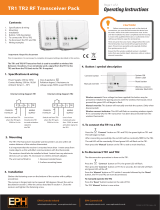
AT-8070-D Control Board for swinging gates
DESCRIPTION
P1A = Operating time programming button
P2B = Remote control programming button
DSW1 = Micro Switches
TR1, TR2, TR3 = Adjustable trimmers
RESET = Reset Button
F2 = Low Voltage Fuse
TF1 = Transformer
CN1 = Receiver
M1 = Low Voltage Input Terminal
F1 = 230Vac Fuse
M2 = 230Vac Input Terminal
K1 – K3 = Relay
2
EN60950
EN301489-1
EN301489-3
EN300220-3
Radio & Telecommunications Terminal Equipment directive 1999/5/EC
AUTOTECH - G .KAPSALIS
8, Archimidous str. 12134 Peristeri Athens,
Greece, Tel: +302105780019, Fax: +302105785112
In accordance with the following directives:
DECLARATION OF CONFORMITY
hereby declare that:
Product : AT8070 Remote Control Board for Opening Doors
Model : AT-8070-D
is in conformity with the applicable
requirements of the following documents.
I hereby declare that the equipment named above has been designed to
comply with the relevant sections of the above referenced specifications.
The unit complies with all the applicable essential requirements of the
directives mentioned.
Name: Apergis Antonios
Position: Technical Director
Peristeri, 28 November 2013
F2
TR1 TR2 TR3
P1A
P2B
CN1
M1
F1
M2
K1
K2
K3
TF1
RESET

INSTALLATION
2
1,5mm
Prior to the electric connection shut down the 230V 50Hz power supply and adjust motor torch to
minimun.
2
Use 0,5mm to connect the buttons, photocells and 24V power supply. For connections with electric bolt
and lights use at least cables. For 230V 50Hz connections and motor connections use at least
2
2.5mm cables.
Termina M1l
ANT = Antenna
COM = Input and Flashing light Common
START = Input Button N.O. (Open / Close)
ST.PED = Input Button N.O. (Pedestrian Open)
STOP = Input Button N.C. (STOP)
SAFETY = Safety Contact Input N.C.
COM = Input and Flashing light Common
PHOTO-1 = External Photocell Command Input N.C.
PHOTO-2 = Internal Photocell Command Input N.C.
W. LΙGHT 2W 24V = Flashing Light 24Vdc 2W max. Output
+24V = +24Vdc Power Supply
-24V = -24Vdc Power Supply
LOCK = 12Vac Electric Lock Output
Terminal Μ2
PE = Ground Input
L = Line Input 230V 50Hz
N = Neutral Input 230V 50Hz (Electric Light Common)
FLASH = Electric Light 230V 50Hz 15 W max.
Motor 1 COM = Motor 1 Common
Motor 1 C = Motor 1 Close
Motor 1 O = Motor 1 Open
Motor 2 COM = Motor 2 Common
Motor 2 C = Motor 2 Close
Motor 2 O = Motor 2 Open
-
. N.C.
-
- If one of the Ν.Ο. (START and S.TP) is closed, or one of the N.C.inputs is openthe TEST_LED blinks fast. In this case
track programming is not available.
It is very important to firmly tight the signal cables of terminal Μ2
and power cables on terminal M1 separately to avoid errors Use Jumpers to all inputs when not in use.
Do not connect any kind of device in the terminal inputs other than the one they are designed for.
OPERATION MODES
CONDOMINIUM AUTOMATIC:
If the door is closed or closing and you press START button the door opens. If the door is opening, START command is
ignored, while during auto close, START command resets time. If you press START after STOP command the door
closes.
SUPERAUTOMATIC:
If the door is closed or closing and you press START button the door opens. if the door is opening START command
stops the door. During auto close, START command closes the door. If you press START after STOP command the
door closes.
AUTOMATIC:
If the door is closed or closing and you press START button the door opens. START command is ignored while the door
is open.During auto close, START command closes the door. If you press START after STOP, command the door
closes.
SEMIAUTOMATIC:
START command controls opening, closing and stoping the door. When the door is open you must press START to
close the door .Auto close is disabled. If the door is opening and you press START the door stops and you must give a
second START command to close the door. If START is pressed during closing function, the door starts to open. If you
press START after a STOP command the door closes.
STEP BY STEP:
When the door is closed and you press START, the door opens. During opening if START is pressed, the door stops. if
you then press START the door closes and by pressing START again the door stops. if you press START after a STOP
command, the door closes.
Choose operation mode with micro Switches 1,2,3 and 6, according to the following board “CHOOSE
OPERATION MODE” (after each change of operation mode you must short circuit jumper JR1 for a few seconds
to apply change).
(1) Comfort operation allows the door to close 5 seconds after the photocells command, independent of the AUTO
CLOSE programmed time.
(2) Photocell retrigger resets AUTO CLOSE time after any command from Photocells.
OFF OFF OFF OFF Condominium automatic
OFF OFF ON OFF Condominium automatic + comfort (1)
OFF ON OFF OFF Superautomatic
OFF ON ON OFF Superautomatic + comfort (1)
ON ON OFF OFF Automatic
ON ON ON OFF Automatic + comfort (1)
ON OFF OFF OFF Semiautomatic
ON OFF ON OFF Step by Step
OFF OFF OFF ON Condominium automatic + photocell retrigger (2)
OFF ON OFF ON Superautomatic + photocell retrigger (2)
ON ON OFF ON Automatic + photocell retrigger (2)
CHOOSE OPERATION MODE
Dip 1 Dip 2 Dip 3 Dip 6 OPERATION
3

SETTINGS
Through micro(DIP) switches 4,5,7 and 8 the following settings may be applied.
Dip switch OPERATION ON OFF
4 Preflashing Enabled Disabled
5 Revert movement Enabled Disabled
7 Lighting operation LIGHT BEACON
8 Max torch at closing ending Enabled Disabled
ADJUSTABLE TRIMMER
TR1 adjusts auto close time (the time the door remains open before closes automatically),with range from 1 to 120 seconds.
TR2 adjusts motor torch. For motors with clutch or hydraulic oil pressure you must set TR2 to maximum (that is one full turn
to the right).
TR3 adjusts door speed at slow motion mode, which can be set according to safety parameters. By setting TR3 to maximum
(that is one full turn to the right) slow speed is disabled. (see. Operation time programming without slow speed).
Trimmer Operation Range Special Functions
TR1 Auto Close 1 – 120 seconds -
TR2 Motor Torch 20 – 100 % 100 % ( Hydraulic or clutched motors)
TR3 Slow Speed 10 – 100 % 100 % = Slow Speed Disabled
REMOTE CONTROL PROGRAMMING
AT-8070-D control board has a built in receiver that can store upt o 128 Rolling coded remote controls or one fixed coded
remote control.
Remote control programming for total door open
If the door is closed, press RADIO and hold it until TEST LED starts blinking. Release RADIO and within 10 seconds, press
the remote control you want to program. When the procedure is completed TEST LED and the FLASHING LIGHT must turn
ON ant then OFF simultaneously. For rolling coded remote controls repeat procedure for each control. For Fixed coded
remote controls just copy the remote controls.
Remote control programmin for pedestrian
When the door is closed press until TEST LED starts blinking. Do not relase TEST LED starts blinking faster.
Realease RADIO . Within 10 seconds, press the button of the remote control you want to program.
When the procedure is completed TEST LED and the FLASHING LIGHT must turn ON ant then OFF simultaneously.
For rolling coded remote controls repeat procedure for each control. For Fixed coded remote controls just copy the remote
controls.
Erase all remote controls
When the door is closed press RADIO and hold it until TEST LED starts blinking. Do not relase TEST LED until it starts
blinking faster. µέχρι το TEST LED. When all remote controls are erased from memory TEST LED and the FLASHING LIGHT
must turn ON ant then OFF simultaneously.
MAINTENANCE
There are two 5 Χ 20 fuses for the 230Vac line and the low voltage that is supplied from the transformers secondary coil. The
fuses have the following values
F1 Line Fuse 230Vac = 6,3 Slow burning
F2 Low Voltage Fuse = 1,25 A Slow burning
Prior to replacing the fuses the power supply must be turned off from the main electrical supply.
The value of the fuses must not be altered.
There is no other element on the control board that can be repaired or replaced from installation
personnel. For any other issue contact technical support.
RADIO
230Vac
4

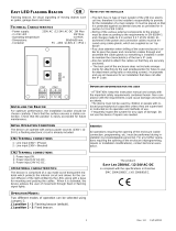
OPERATION TIME PROGRAMMING FOR TWO LEAFED SWINGING GATE WITH SLOW SPEED
Set trimmer TORQUE at minimum needed to move the door leaf correctly and adjust trimmer for slow
speed at minimum needed to move the door leafs .
Totally close the door.
Press PROGR for at least 3 seconds.
TEST LED starts blinking.
Release
Press START: The first leaf starts moving at normal speed.
When you want to start slow speed press START: Slow speed mode has began.
When first leaf is totally open press START: The second leaf starts opening at normal speed.
When you want to start slow speed for the second leaf press START: Slow speed has began.
When the second leaf is totally open press START: The second leaf starts closing at normal speed.
When you want to start slow speed for the second leaf press START: Slow speed has began.
When the second leaf is totally closed press START: The first leaf starts closing at normal speed.
When you want to start slow speed for the first leaf press START: Slow
When the firtst leaf is totally closed press START.
Press START: the first leaf starts opening and when you decide that the time interval between the opening of
the two leafes is enough press START again: The second leaf starts opening.
Press START: The second leaf starts closing and when you decide that the time interval between the closing of
the two leafes is enough press START again: The first leaf starts closing.
Wait until the TEST LED turns off.
The operation time programming is complete.
The next time the door will open will be according to the settings just completed.
ATTENTION:
After RESET or power supply failure, at the first closing of the door the operation time will be greater
(approximately 12 seconds)
correctly
PROGR
speed has began.
SLOW
M2
M1
M2
M1
M2
M1
M2
M1
M2
M1
M2
M1
M2
M1
M2
M1
M2
M1
M2
M1
M2
M1
M2
M1
2
START
3
START
4
START
5
START
6
START
7
START
8
START
9
START
10
START
11
START
12
START
13
START
M2
M1
1
START
First START command initiates
the operation time programming
causing the first motor to OPEN.
Second START command defines the point
at which slow speed begins
for the first motor while opening.
Third START command defines
the end of first motor operation time
and must be issued when the door
totally opens.
Fourth START command defines
the starting point for slow speed
for the second motor while opening.
Fifth START command defines
the end of the second motor
operation time and must be issued
when the doors totally opens.
Sixth START command defines
starting point for slow speed for the
second motor while closing.
Seventh START command defines
the end of the second motor
operation time and must be issued
when the door totally closes.
Eighth START cpmmand defines
the starting
point for slow speed for the first motor
while closing.
Ninth START command defines
the end of the first motor operation time
and must be issued when the door
totally closes.
Tenth START command initiates
the programming for the operation time
interval between the
two leafs of the door when opening.
Eleventh START command starts the
second motor after the desired time interval
between the opening of the two motors.
Thirteenth START command starts the
first motor for the operation time interval
between the two leafs of the door
when closing.
Twelfth START command initiates
the programming for the operation time
interval between the two leafs
of the door when closing.
5

OPERATION TIME PROGRAMMING FOR TWO LEAFED SWINGING GATE WITHOUT SLOW SPEED
Set trimmer TORQUE at minimum needed to move the door leaf correctly and adjust trimmer for slow
speed at maximum needed to move the door leafs correctly.
Totally close the door.
Press for at least 3 seconds.
TEST LED starts blinking.
Release
Press START: The first leaf starts moving at normal speed.
When first leaf is totally open press START: The second leaf starts opening at normal speed.
When the second leaf is totally open press START: The second leaf starts closing at normal speed.
When the second leaf is totally closed press START: The first leaf starts closing at normal speed.
Press START: the first leaf starts opening and when you decide that the time interval between the opening of
the two leafes is enough press START again: The second leaf starts opening.
Press START: The second leaf starts closing and when you decide that the time interval between the closing of
the two leafes is enough press START again: The first leaf starts closing.
Wait until the TEST LED turns off.
The operation time programming is complete.
The next time the door will open will be according to the settings just completed.
ATTENTION:
After RESET or power supply failure, at the first closing of the door the operation time will be greater
(approximately 12 seconds)
PROGR
PROGR
SLOW
M2
M1
M2
M1
1
START
2
START
M2
M1
2
START
M2
M1
4
START
M2
M1
5
START
M2
M1
6
START
M2
M1
7
START
M2
M1
8
START
M2
M1
9
START
First START command initiates
the operation time programming
causing the first motor to OPEN.
Third START command defines
the end of first motor operation time
and must be issued when the door
totally opens.
Third START command defines
the end of the second motor
operation time and must be issued
when the doors totally opens.
Fourth START command defines
the end of the second motor
operation time and must be issued
when the door totally closes.
Fifth START command defines
the end of the first motor operation time
and must be issued when the door
totally closes.
Sixth START command initiates
the programming for the operation time
interval between the
two leafs of the door when opening.
Seventh START command starts the
second motor after the desired time interval
between the opening of the two motors.
Eighth START command initiates
the programming for the operation time
interval between the two leafs
of the door when closing.
Ninth START command starts the
first motor for the operation time interval
between the two leafs of the door
when closing
6

OPERATION TIME PROGRAMMING FOR SINGLE LEAFED SWINGING GATE WITH SLOW SPEED
Set trimmer TORQUE at minimum needed to move the door leaf correctly and adjust trimmer for slow speed
at minimum needed to move the door correctly .
Totally close the door.
When you want to start slow speed press START: Slow speed mode has began.
When the door is totally open press START: The door closing at normal speed.
When you want to start slow speed for the door press START: Slow speed has began.
When the door is totally closed press START.
Wait until the TEST LED turns off.
The operation time programming is complete.
The next time the door will open will be according to the settings just completed.
ATTENTION:
After RESET or power supply failure, at the first closing of the door the operation time will be greater
(approximately 12 seconds)
Press PROGR until starts blinking and do not release PROGR until starts blinking faster.
PROGR
The door starts moving at normal speed.
SLOW
TEST LED TEST LED
Release
Press START:
M1
2
START
M1
4
START
First START command initiates
the operation time programming
causing the door to OPEN.
Second START command defines
the starting point for slow speed
for the door while opening
Third START command defines
the end of door operation time
and must be issued when the door
totally opens
Fourth START command defines
starting point for slow speed for the
door while closing.
Fifth START command defines
the end of the door operation
time and must be issued
when the door totally closes.
OPERATION TIME PROGRAMMING FOR SINGLE LEAFED SWINGING GATE WITHOUT SLOW SPEED
at maximum needed to move the door correctly .
Totally close the door.
Press PROGR until TEST LED starts blinking and do not release PROGR until TEST LED starts blinking faster.
Release PROGR
Press START: The door starts moving at normal speed.
When the door is totally open press START: The door closing at normal speed.
When the door is totally closed press START.
Wait until the TEST LED turns off.
The operation time programming is complete.
The next time the door will open will be according to the settings just completed
ATTENTION:
After RESET or power supply failure, at the first closing of the door the operation time will be greater
(approximately 12 seconds)
Set trimmer TORQUE at minimum needed to move the door leaf correctly and adjust trimmer for slow speed SLOW
.
.
M1
1
START
M1
2
START
M1
3
START
First START command initiates
the operation time programming
causing the door to OPEN..
Third START command defines
the end of the door operation time
and must be issued when the door
totally opens
Third START command defines
the end of the door operation
time and must be issued
when the door totally closes
M1
1
START
M1
3
START
M1
5
START
7

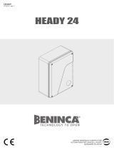
OPERATION COMMANDS
PEDESTRIAN
START
LIGHT
24V / 2W
BUTTON KEY
RX TX
INTERNAL PHOTOCELLS EXTERNAL PHOTOCELLS
RX TX
FLASHLIGHT
230V / 25W
MAX
ELECTRIC LOCK
12VAC/DC 15W
POWER SUPPLY
BIPOLAR THERMOMAGNETIC
SWITCH WITH DIFFERENTIAL
6A / 30ma
8
1 2 3 4 5 6 7 8 9 10 11 12 13 14
15 16 17 18 19 20 21 22 23 24 25
DL1
DL2
DL3
DL4
DL5
DL6
START STOP
ΝΟ ΝΟΝC
24V
2W
MAX
ΝΟ
ΝC
COM
+
-
NO
COM
NC
+
-
+
-
NO
COM
NC
+
-
230VAC
COM
CLOSE
OPEN
C
COM
CLOSE
OPEN
ΝC
TOTAL
STOP
C
M1
M2
MOTOR-1
MOTOR-2
20
21
22
23
24
25
16
17
11
12
19 18
1
6,10
2
3
9
1
6,10
7
8
5
4
/