Page is loading ...
MULTICOM
®
PRO MDX4400
www.behringer.com
E
Users Manual
Version 1.3 April 2001
ENGLISH
Downloaded from www.Manualslib.com manuals search engine

2
MULTICOM PRO MDX4400
This symbol, wherever it appears, alerts
you to important operating and mainte-
nance instructions in the accompanying
literature. Read the manual.
SAFETY INSTRUCTIONS
CAUTION: To reduce the risk of electric shock, do not remove
the cover (or back). No user serviceable parts inside;
refer servicing to qualified personnel.
WARNING: To reduce the risk of fire or electric shock, do not
expose this appliance to rain or moisture.
DETAILED SAFETY INSTRUCTIONS:
All the safety and operation instructions should be read before the appliance is operated.
Retain Instructions:
The safety and operating instructions should be retained for future reference.
Heed Warnings:
All warnings on the appliance and in the operating instructions should be adhered to.
Follow instructions:
All operation and user instructions should be followed.
Water and Moisture:
The appliance should not be used near water (e.g. near a bathtub, washbowl, kitchen sink, laundry tub, in a wet
basement, or near a swimming pool etc.).
Ventilation:
The appliance should be situated so that its location or position does not interfere with its proper ventilation.
For example, the appliance should not be situated on a bed, sofa, rug, or similar surface that may block the
ventilation openings, or placed in a built-in installation, such as a bookcase or cabinet that may impede the
flow of air through the ventilation openings.
Heat:
The appliance should be situated away from heat sources such as radiators, heat registers, stoves, or other
appliances (including amplifiers) that produce heat.
Power Source:
The appliance should be connected to a power supply only of the type described in the operating instructions
or as marked on the appliance.
Grounding or Polarization:
Precautions should be taken so that the grounding or polarization means of an appliance is not defeated.
Power-Cord Protection:
Power supply cords should be routed so that they are not likely to be walked on or pinched by items placed
upon or against them, paying particular attention to cords and plugs, convenience receptacles and the point
where they exit from the appliance.
Cleaning:
The appliance should be cleaned only as recommended by the manufacturer.
Non-use Periods:
The power cord of the appliance should be unplugged from the outlet when left unused for a long period of time.
Debris and Liquid Entry:
Care should be taken that debris and/or liquids do not enter the enclosure through openings.
Damage Requiring Service:
The appliance should be serviced by qualified service personnel when:
- The power supply cord or the plug has been damaged; or
- Debris or liquid has entered the appliance; or
- The appliance has been exposed to rain; or
- The appliance does not appear to operate normally or exhibits a marked change in performance; or
- The appliance has been dropped, or the enclosure damaged.
Servicing:
The user should not attempt to service the appliance beyond that which is described in the operating instruc-
tions. All other servicing should be referred to qualified service personnel.
This symbol, wherever it appears,
alerts you to the presence of
uninsulated dangerous voltage inside
the enclosurevoltage that may be
sufficient to constitute a risk of shock.
Downloaded from www.Manualslib.com manuals search engine

3
MULTICOM PRO MDX4400
FOREWORD
Dear Customer,
Welcome to the team of MULTICOM PRO users and thank you very much for expressing your confidence in
BEHRINGER products by purchasing this unit.
It is one of my most pleasant tasks to write this letter to you, because it is the culmination of many months of
hard work delivered by our engineering team to reach a very ambitious goal: making an outstanding device
better still. The MULTICOM has for quite a long time been a standard tool used by numerous studios and
PA rental companies. The task to improve one of our best-selling products certainly meant a great deal of
responsibility, which we assumed by focusing on you, the discerning user and musician. It also meant a lot of
work and night shifts to accomplish this goal. But it was fun, too. Developing a product usually brings a lot of
people together, and what a great feeling it is when everybody who participated in such a project can be proud
of what weve achieved.
It is our philosophy to share our joy with you, because you are the most important member of the BEHRINGER
family. With your highly competent suggestions for new products youve greatly contributed to shaping our
company and making it successful. In return, we guarantee you uncompromising quality (manufactured under
the ISO9000 certified management system) as well as excellent technical and audio properties at an
extremely favorable price. All of this will enable you to fully unfold your creativity without being hampered by
budget constraints.
We are often asked how we can make it to produce such high-grade devices at such unbelievably low prices.
The answer is quite simple: its you, our customers! Many satisfied customers means large sales volumes
enabling us to get better conditions of purchase for components, etc. Isnt it only fair to pass this benefit back
to you? Because we know that your success is our success, too!
I would like to thank all people whose help on Project MULTICOM PRO has made it all possible. Everybody
has made very personal contributions, starting from the designers of the unit via the many staff members in our
company to you, the user of BEHRINGER products.
My friends, its been worth the trouble!
Thank you very much,
Uli Behringer
Downloaded from www.Manualslib.com manuals search engine

4
MULTICOM PRO MDX4400
MDX4400
MULTICOM
®
PRO
Interactive 4-channel compressor/limiter/peak limiter of the reference class
s
IKA (Interactive Knee Adaptation) compressor concept combines the advantages of hard knee and
soft knee characteristics
s
Switchable highpass filter in control signal path avoids low-frequency signals from dominating compressor
action
s
Compression characteristics switchable between IKA and hard knee characteristics
s
IGC (Interactive Gain Control) peak limiter combines clipper with program limiter circuits
s
Extremely low-noise operational amplifiers and high-grade VCAs
s
High-quality detent potentiometers and backlit switches
s
Stereo Couple function for channels 1/2 and 3/4 selectable with real totaling of RMS output
s
Accurate 8-digit LED meters for input level, output level and gain reduction
s
Operating level switchable from +4 dBu to -10 dBV
s
Servo-balanced inputs and outputs featuring 1/4" jacks and XLR connectors
s
Manufactured under ISO9000 certified management system
Downloaded from www.Manualslib.com manuals search engine

5
MULTICOM PRO MDX4400
TABLE OF CONTENT
1. INTRODUCTION..................................................................................................................... 6
1.1 Technical Background ..................................................................................................................... 7
1.1.1 Noise As A Physical Phenomenon ........................................................................................ 7
1.1.2 What Are Audio Dynamics? .................................................................................................. 7
1.1.3 Compressors/Limiters ........................................................................................................... 9
2. THE DESIGN CONCEPT ..................................................................................................... 10
2.1 High Quality Components And Design ...........................................................................................10
2.2 Inputs And Outputs ....................................................................................................................... 10
2.2.1 Balanced Inputs And Outputs.............................................................................................. 10
3. INSTALLATION ..................................................................................................................... 11
3.1 Rack Mounting ............................................................................................................................... 11
3.2 Mains Voltage ................................................................................................................................ 11
3.3 Audio Connections ......................................................................................................................... 11
3.4 Selecting The Operating Level ....................................................................................................... 12
4. CONTROLS .......................................................................................................................... 13
4.1 The Front Panel Control Elements ................................................................................................ 13
4.4 Rear Panel Control Elements Of The MULTICOM PRO ................................................................. 15
5. APPLICATIONS ..................................................................................................................... 16
5.1 Compression/Leveling/Limiting/Clipping ......................................................................................... 16
5.2 Compressor Section ..................................................................................................................... 17
5.2.1 Initial Settings For The Compressor Section ....................................................................... 18
5.2.2 The MULTICOM PRO As A Sound Effects Unit .................................................................... 18
5.2.3 The Muffling Effect Of A Compressor ................................................................................. 18
5.3 Peak Limiter Section..................................................................................................................... 19
5.3.1 Initial Settings For The Peak Limiter Section ....................................................................... 19
6. SPECIAL APPLICATIONS ..................................................................................................... 20
6.1 Using The MULTICOM PRO For Recording And Cassette Duplication ........................................... 20
6.1.1 The MULTICOM PRO In Digital Recording And Sampling .................................................... 20
6.1.2 The MULTICOM PRO In Mastering ...................................................................................... 20
6.2 The MULTICOM PRO as a protective device .................................................................................. 20
6.2.1 Protection Of A System With A Passive Crossover .............................................................. 21
6.2.2 Protection Of A System With An Active Crossover............................................................... 21
6.2.3 Improving The Sound Of A Processor System ..................................................................... 21
6.3 The MULTICOM PRO In Broadcast ............................................................................................... 22
7. SPECIFICATIONS .................................................................................................................. 23
8. WARRANTY ........................................................................................................................... 25
Downloaded from www.Manualslib.com manuals search engine

6
MULTICOM PRO MDX4400
1. INTRODUCTION
In purchasing the MULTICOM PRO, you have acquired an extremely efficient and universal dynamics
processor. The unit was particularly designed for those applications most frequently used in practice. Despite
the extremely complex internal circuitry, the unit has a control surface which is clearly laid out and easy to
understand. With the MULTICOM PRO, BEHRINGER have developed an innovative and easy-to-use dynamics
processor which meets the high demands that are made on such a device both in live and studio applications.
The units most outstanding features are the precision and flexibility of its functions.
Quad compressor/limiters are actually not a new invention. Usually, four simple compressor sections are
packed into one enclosure, representing however a compromise in terms of operation and functionality. An
excessive number of controls complicates the operation of the unit and a lack of control functions restricts the
units range of application.
The BEHRINGER MULTICOM PRO is a compact quad compressor/limiter based on the successful BEHRINGER
Interactive Technology. Integrated AUTO processors automatically derive attack and release times from the
programme material and provide you with transparent and inaudible compression. In 1 RU package the unit
consists of four independent high-precision compressor sections with sidechain filters and four peak limiters,
each offering all the required controls.
With rack space at a premium both in the studio and in sound reinforcement, the MULTICOM PROs unique
high density design and clean uncluttered layout makes it a truly useful audio tool for all applications. The
MULTICOM PRO is a perfect and extremely cost-effective solution for all your multi-channel dynamic
applications.
Advanced BEHRINGER Technology
Compared to its predecessors, the MULTICOM PRO offers several advanced features such as the extended
LED meters, the sidechain filter, the controlable peak limiter per channel and the couple function for two
channels. Additionally, we have succeeded in refining the audio properties as well as the circuit topology.
For the first time, the MULTICOM PRO MDX 4400 uses SMD technology (Surface Mounted Device). These
sub-miniature components known from aerospace technology allow for an extreme packing density, plus
improve the units reliability.
IKA (Interactive Knee Adaptation) Compressor
Our proven IKA (Interactive Knee Adaptation) circuit successfully combines the concept of a hard knee
compressor with the characteristics of a soft knee approach. This program-dependent regulation scheme
forms the prerequisite both for inaudible and musical program compression and for creative and highly
effective dynamics processing.
With its IKA circuit the MULTICOM PRO is capable of delivering outstanding musical results both in studio and
live PA applications.
Additionally, the MULTICOM PROs sidechain filter allows for limiting the influence low-frequency signal
portions usually have on the control logic, so that the compression ratio is mainly determined by those
frequencies that are essential to the loudness perceived by the listenerthe midrange frequencies.
AUTO COMPRESSOR Circuitry
The response of a compressor and the quality of dynamics processing largely depend on the control times,
i.e., the attack and release functions. In particular, in the field of musical compression of complex composite
signals, programme-dependent control times are necessary. The interactive AUTO processor derives the
attack and release times automatically from the programme material, a function that avoids misadjustment of
the control times, which is a problem often encountered in conventional designs. In addition the AUTO
processor allows for a high compression of the dynamic range without any audible side effects, such as
pumping, breathing etc.
IGC (Interactive Gain Control) Peak Limiter
A further remarkable feature of the BEHRINGER MULTICOM PRO is the IGC (Interactive Gain Control) Limiter,
an intelligent combination of a clipper and a program limiter. Above an adjustable threshold the peak limiter
begins to function and restricts signal peaks radically (clipper). If however, the threshold of the limiter was
surpassed for more than a few milliseconds, the IGC circuit automatically kicks in and reduces the level of the
1. INTRODUCTION
Downloaded from www.Manualslib.com manuals search engine

7
MULTICOM PRO MDX4400
overall output signal so that no audible distortion occurs (program limiter). After the level falls below the thresh-
old, the signal returns to the original value after a period of about 1 second. This IGC circuit proves to be
extremely valuable as much for live work (loudspeaker protection) as for digital situations, where any extreme
signal peaks would exceed the maximum headroom and therefore would cause severe problems.
+ The following instructions should initially familiarize you with the special terms used, so that
you can get to know all the functions of the unit. After you have read the instructions carefully,
please put them away safely, so that you can refer to them again if necessary.
1.1 Technical Background
By employing current modern analogue technology it is possible to manufacture audio equipment with a
dynamic range of up to 125 dB. In contrast to analogue techniques, the dynamic range of digital equipment is
approximately 25 dB less. With conventional record and tape recorder technology, as well as broadcasting,
this value is further reduced. Generally, dynamic restrictions are due to noisy storage in transmission media
and also the maximum headroom of these systems.
1.1.1 Noise As A Physical Phenomenon
All electrical components produce a certain level of inherent noise. Current flowing through a conductor leads
to uncontrolled random electron movements. For statistical reasons, this produces frequencies within the
whole audio spectrum. If these currents are highly amplified, the result will be perceived as noise. Since all
frequencies are equally affected, we term this white noise. It is fairly obvious that electronics cannot function
without components. Even if special low-noise components are used, a certain degree of basic noise cannot
be avoided.
This effect is similar when replaying a tape. The non-directional magnetic particles passing the replay head can
also cause uncontrolled currents and voltages. The resulting sound of the various frequencies is heard as
noise. Even the best possible tape biasing can only provide signal-to-noise ratios of about 70 dB, which is not
acceptable today since the demands of listeners have increased. Due to the laws of physics, improving the
design of the magnetic carrier is impossible using conventional means.
1.1.2 What Are Audio Dynamics?
A remarkable feature of the human ear is that it can detect the most wide ranging amplitude changesfrom the
slightest whisper to the deafening roar of a jet-plane. If one tried to record or reproduce this wide spectrum of
sound with the help of amplifiers, cassette recorders, records or even digital recorders (CD, DAT etc.), one
would immediately be restricted by the physical limitations of electronic and acoustic sound reproduction
technology.
The usable dynamic range of electro-acoustic equipment is limited as much at the low end as at the high end.
The thermal noise of the electrons in the components results in an audible basic noise floor and thus repre-
sents the bottom limit of the transmission range. The upper limit is determined by the levels of the internal
operating voltages; if they are exceeded, audible signal distortion is the result. Although in theory, the usable
dynamic range sits between these two limits, it is considerably smaller in practice, since a certain reserve
must be maintained to avoid distortion of the audio signal if sudden level peaks occur. Technically speaking,
we refer to this reserve as headroomusually this is about 10 - 20 dB. A reduction of the operating level would
allow for greater headroom, i.e. the risk of signal distortion due to level peaks would be reduced. However, at
the same time, the basic noise floor of the program material would be increased considerably.
1. INTRODUCTION
Downloaded from www.Manualslib.com manuals search engine
8
MULTICOM PRO MDX4400
Ear
Microphone Amplifier
Power Amplifier
Tape Recorder
Radio
Cassette
Recorder
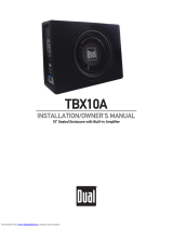
P/dB
140
120
100
80
60
40
Fig. 1.1: The dynamic range capabilities of various devices
It is therefore useful to keep the operating level as high as possible without risking signal distortion in order to
achieve optimum transmission quality.
It is possible to further improve the transmission quality by constantly monitoring the program material with the
aid of a volume fader, which manually levels the material. During low passages the gain is increased, during
loud passages the gain is reduced. Of course it is fairly obvious that this kind of manual control is rather
restrictive; it is difficult to detect signal peaks and it is almost impossible to level them out. Manual control is
simply not fast enough to be satisfactory.
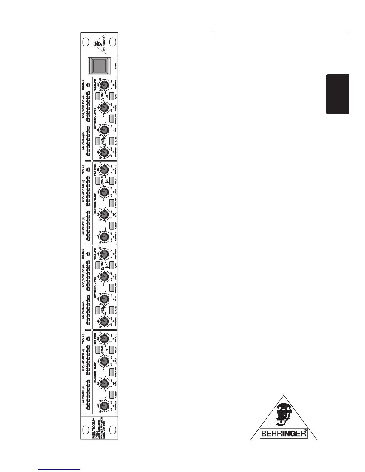
t
P/dB
+20
0
-20
-40
-60
-80
Clipping
Headroom
Operating level
Effective SNR
Noise floor
Fig. 1.2: The interactive relationship between the operating level and the headroom
The need therefore arises for a fast acting automatic gain control system which will constantly monitor the
signals and which will always adjust the gain to maximize the signal-to-noise ratio without incurring signal
distortion. This device is called a compressor or limiter. This system is a part of the BEHRINGER MULTICOM
PRO.
1. INTRODUCTION
Downloaded from www.Manualslib.com manuals search engine

9
MULTICOM PRO MDX4400
1.1.3 Compressors/Limiters
By measuring the dynamic range of musical instruments in live recording situations, you will find that extreme
amplitudes occur which often lead to overload in subsequent signal processing equipment. Especially in
broadcasting and record cutting techniques, these signal peaks can lead to heavy distortion. To avoid this kind
of distortion or, for example, to avoid loudspeakers being damaged by overload, compressors or limiters are
used.
The principal function used in these devices is dependent on an automatic gain control as mentioned in the
previous section, which reduces the amplitude of loud passages and therefore restricts the original dynamics
to a desired range. This application is particularly useful in microphone recording techniques, to compensate
for level changes which are caused by varying microphone distances. Although compressors and limiters
perform similar tasks, one essential point makes them different: limiters abruptly limit the signal above a
certain level, while compressors control the signal gently over a wider range. A limiter continuously monitors
the signal and intervenes as soon as the level exceeds a user-adjustable threshold. Any signal exceeding this
threshold will be immediately returned to the adjusted level.
A compressor also monitors the program material continuously and has a certain threshold level. With com-
pression, in contrast to the action of a limiter, signals are not reduced in level abruptly once the threshold has
been exceeded, but are returned to the threshold gradually. The signal is reduced in gain, relative to the
amount the signal exceeds this point.
Generally, threshold levels for compressors are set below the normal operating level to allow for the upper
dynamics to be musically compressed. For limiters, the threshold point is set above the normal operating level
in order to provide reliable signal limiting, to protect subsequent equipment from signal overload.
1. INTRODUCTION
Downloaded from www.Manualslib.com manuals search engine

10
MULTICOM PRO MDX4400
2. THE DESIGN CONCEPT
2.1 High Quality Components And Design
The philosophy behind BEHRINGER products guarantees a no-compromise circuit design and employs the
best choice of components. The operational amplifiers NJM4580 which are used in the MULTICOM PRO, are
exceptional. They boast extreme linearity and very low distortion characteristics. The most important aspect of
the MULTICOM PRO design is a radical VCA implementation which results in outstanding technical specifica-
tion and excellent performance. To complement this design the choice of components includes high tolerance
resistors and capacitors, detent potentiometers and several other stringently selected elements.
For the first time, the MULTICOM PRO MDX 4400 uses SMD technology (Surface Mounted Device). These
sub-miniature components known from aerospace technology allow for an extreme packing density, plus the
units reliability could be improved. Additionally, the unit is manufactured under ISO9000 certified management
system.
2.2 Inputs And Outputs
2.2.1 Balanced Inputs And Outputs
As standard, the BEHRINGER MULTICOM PRO is installed with electronically servo-balanced inputs and
outputs. The new circuit design features automatic hum and noise reduction for balanced signals and thus
allows for trouble-free operation, even at high operating levels. Externally induced mains hum etc. will be
effectively suppressed. The automatic servo-function recognizes the presence of unbalanced connectors and
adjusts the nominal level internally to avoid level differences between the input and output signals (correction 6
dB).
2. THE DESIGN CONCEPT
Downloaded from www.Manualslib.com manuals search engine
11
MULTICOM PRO MDX4400
3. INSTALLATION
Your BEHRINGER MULTICOM PRO was carefully packed in the factory and the packaging was designed to
protect the unit from rough handling. Nevertheless, we recommend that you carefully examine the packaging
and ist contents for any signs of physical damage, which may have occurred in transit.
Please also take the time to complete and return the warranty card within 14 days of the date of purchase,
otherwise you will lose the right to the extended warranty. Or simply use our online registration under
www.behringer.com.
+ If the unit is damaged, please do not return it to us, but notify your dealer and the shipping
company immediately, otherwise claims for damage or replacement may not be granted.
Shipping claims must be made by the consignee.
3.1 Rack Mounting
The BEHRINGER MULTICOM PRO fits into one standard 19" rack unit of space (1 3/4"). Please allow at least
an additional 4" depth for the connectors on the back panel. Be sure that there is enough air space around the
unit for cooling and please do not place the MULTICOM PRO on high temperature devices such as power
amplifiers etc. to avoid overheating.
3.2 Mains Voltage
Before you connect your MULTICOM PRO to the mains, please make sure that your local voltage
matches the voltage required by the unit! The fuse holder on the female mains connector has 3 triangular
markers, with two of these triangles opposing each other. Your MULTICOM PRO is set to the operating voltage
printed next to these markers, and can be set to another voltage by turning the fuse holder by 180°. CAUTION:
this instruction does not apply to export models exclusively designed, e.g. for 115 V operation!
3.3 Audio Connections
The audio inputs and outputs on the BEHRINGER MULTICOM PRO are fully balanced. If possible, connect the
unit to other devices in a balanced configuration to allow for maximum interference immunity.
+ Please ensure that only qualified persons install and operate the VIRTUALIZER. During instal-
lation and operation the user must have sufficient electrical contact to earth. Electrostatic
charges might affect the operation of the MULTICOM PRO!
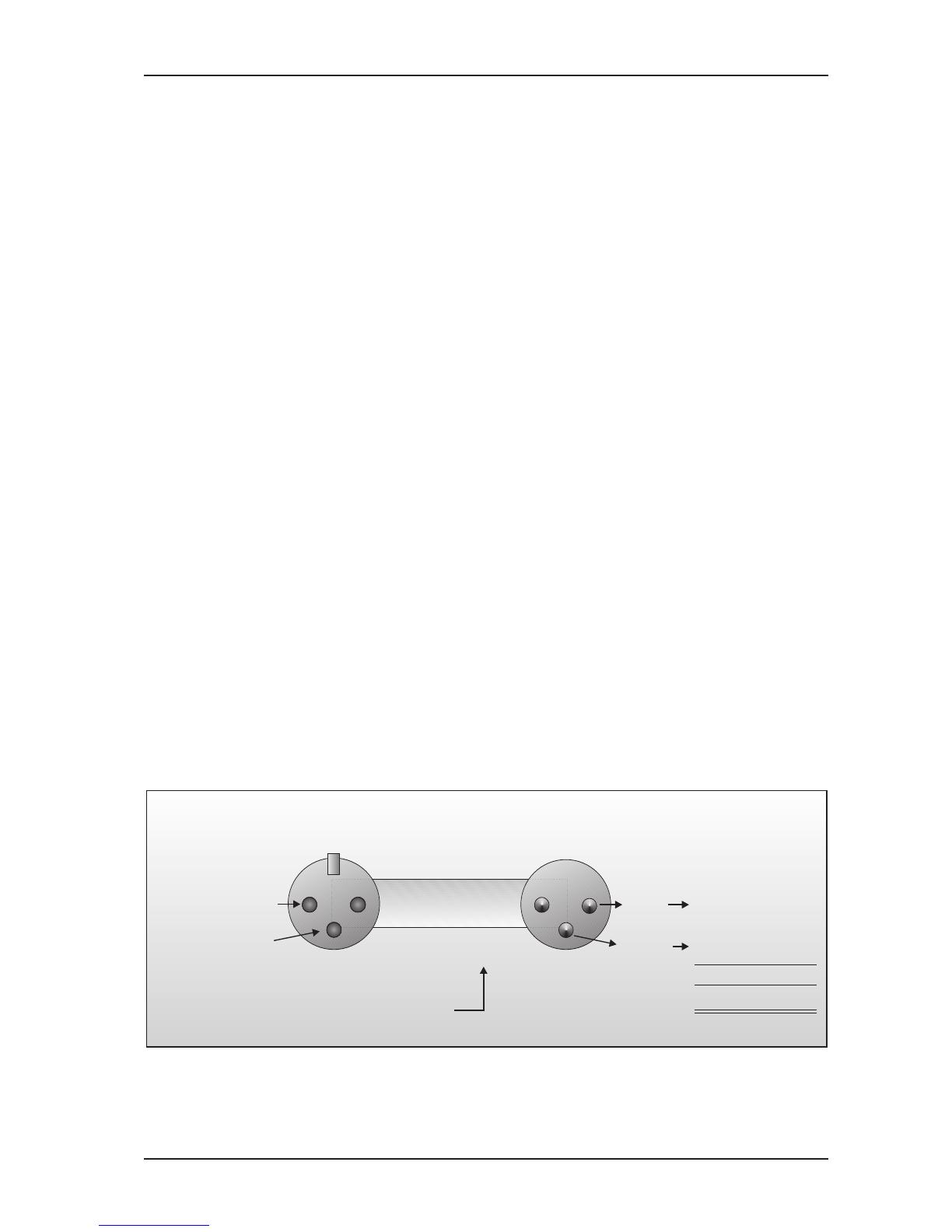
1 2
3
2 1
3
Pin 1
Cable InputOutput
Pin 2 = (+) Signal Positive
Pin 3 = (-) Signal
Shield
(+) Signal + Hum
(-) Signal + Hum
Negative
(+)Hum + Signal
(-)Hum + Signal
2 x Signal
Ground
RFI and Hum
= Signal + 6 dB
Fig. 3.1: Compensation of interference with balanced connections
3. INSTALLATION
Downloaded from www.Manualslib.com manuals search engine

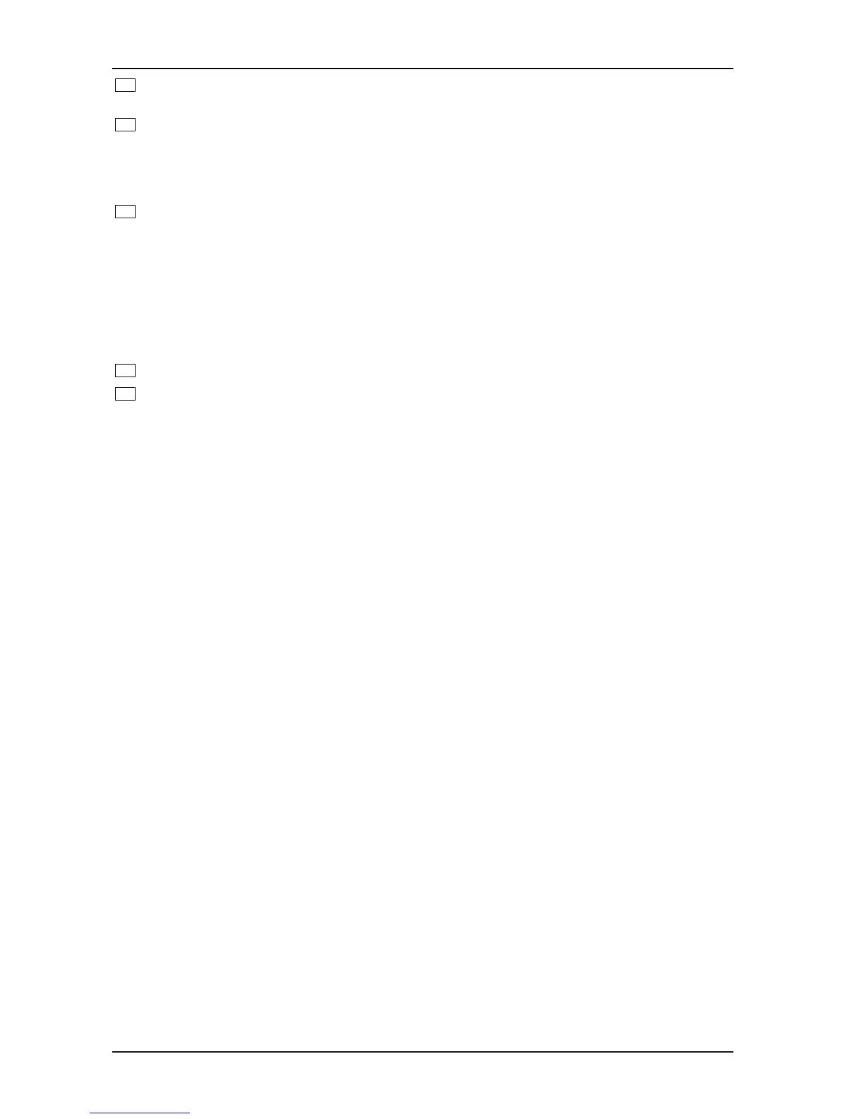
12
MULTICOM PRO MDX4400
Unbalanced use of
mono 1/4" jack plugs
Ring
Balanced use of
stereo 1/4" jack plugs
Balanced use with XLR connectors
1 2
3
2 1
3
Input
Output
Tip =
Signal
Tip =
hot (+ve)
Sleeve =
Ground / Shield
Sleeve =
Ground / Shield
Tip
Tip
Sleeve
Sleeve
Strain relief clamp
Strain relief clamp
Ring =
cold (-ve)
For connection of balanced and
unbalanced plugs, ring and sleeve have
to be bridged at the stereo plug.
1 = Ground / Shield
2 = hot (+ve)
3 = cold (-ve)
For unbalanced use pin 1 and pin 3 have to be bridged
Fig. 3.2: Different plug types
+ Never use unbalanced XLR connections with microphone cables, as this would short-circuit
any phantom power transmitted over these cables!
3.4 Selecting The Operating Level
With the Operating Level switch on the rear of the BEHRINGER MULTICOM PRO you can adjust the internal
operating level of the unit. Thus, the MULTICOM PRO can be adapted perfectly to various levels (e.g. both the
typical home recording level of -10 dBV and the professional level of +4 dBu). The level meters are referenced
automatically to the selected level, i.e. an optimum operating range of the meters will always be ensured.
3. INSTALLATION
Downloaded from www.Manualslib.com manuals search engine

13
MULTICOM PRO MDX4400
4. CONTROLS
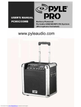
Fig. 4.1: MULTICOM PRO front panel
The BEHRINGER MULTICOM PRO has four identical channels. Each channel is equipped with 4 backlit push-
buttons, 4 rotary controls and 17 LEDs. The COUPLE switches are for stereo operation of two channels.
4.1 The Front Panel Control Elements
11
10
9435261
7
8
Fig. 4.2: Control elements on the front panel
1
The THRESHOLD control sets the threshold point for the compressor section. It has a range of -40 to
+20 dB. If the channel is switched to INTERACTIVE mode (Interactive Knee Adaptation), a Soft Knee
characteristic is applied to the signal exceeding the threshold point by a maximum of 10 dB. Above 10
dB, the signal would experience Hard Knee compression.
2
The RATIO control determines the ratio between the input and output level for all signals exceeding the
threshold point. If the INTERACTIVE mode is used, this control determines the ratio between input and
output levels for signals exceeding the threshold point by more than 10 dB. The control range can be
adjusted from 1:1 to oo:1.
3
The OUTPUT control allows for the increase or decrease of the output signal by a maximum of 20 dB.
Thus, a level loss due to the compression or limiting process can be compensated for.
+ Please note when using the THRESHOLD control of the Peak Limiter section, that the OUTPUT
control of the Compressor section precedes the Peak Limiter section. If the OUTPUT control is
set too high, this can result in continuous peak limiting (see item 9 THRESHOLD control).
4
The IN/OUT switch activates the corresponding channel. This switch acts as a so-called hard-bypass
switch, which means that when the switch is OUT, the input jack is directly linked to the output jack.
Normally, this switch is used to perform a direct A/B comparison between the unprocessed and the
compressed or limited signals.
5
Press the INTERACTIVE switch to change from Hard Knee to IKA characteristics. IKA provides a very
subtle and musical compression of the program material and should therefore be used whenever
compression should be more or less inaudible.
6
The SC FILTER switch activates a highpass filter in the sidechain path and thus limits the influence of
low frequencies on the MULTICOM PROs control processes.
4. CONTROLS
Downloaded from www.Manualslib.com manuals search engine
14
MULTICOM PRO MDX4400
7
The 8-digit GAIN REDUCTION meter indicates how effectively the gain is reduced by the compressor,
within a range from 1 to 30 dB.
8
The 8-digit INPUT/OUTPUT LEVEL meter informs youdepending on the setting of the I/O METER
switchabout the current input or output level, within a range from -24 to +18 dB. When the switch is
set to IN (not engaged), the meter reads the input level, when it is OUT, the output level is displayed. The
meter is referenced to the operating level (-10 dBV or +4 dBu) adjusted with the OPERATING LEVEL
switch on the back.
9
The peak limiter limits the signal to a level adjusted with the THRESHOLD control. Owing to its
extremely fast response (Zero attack), the limiter is capable of limiting signal peaks without audible
distortion. Whenever the signal is limited for more than 20 ms, the overall level is reduced for about 1
second to avoid heavy and thus audible signal distortion.
+ When you use the peak limiter as a protective device against signal peaks, the THRESHOLD
control should be set in combination with the OUTPUT control in the compressor section so
that the peak limiter responds rarely or not at all. Thus, only real signal peaks will activate the
limiter circuit. However, to produce creative sound effects, the peak limiter can be
deliberately set to lower levels.
10
The LIM LED lights up as soon as the limiter function is activated.
11
The MULTICOM PRO converts two channels to stereo mode by engaging one of the COUPLE switches,
where the left of the channels assumes the control of both audio channels, i.e. the control signal of
channel 2 is replaced with that of channel 1. By pressing the COUPLE switch, you override all the
controls and switches of channel 2 (or 4) with the exception of the IN/OUT and SC Filter switches as well
as the peak limiters THRESHOLD control. The controls of channel 1 (or 3) take over all functions of
channel 2 (or 4).
4. CONTROLS
Downloaded from www.Manualslib.com manuals search engine
15
MULTICOM PRO MDX4400
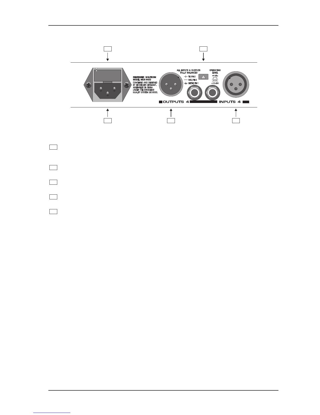
4.4 Rear Panel Control Elements Of The MULTICOM PRO
13
12
14
16
15
Fig. 4.5: Control elements of the rear panel
12
FUSE HOLDER / VOLTAGE SELECTOR. Please make sure that your local voltage matches the volt-
age indicated on the unit, before you attempt to connect and operate the MULTICOM PRO. Blown fuses
may only be replaced by fuses of the same type and rating.
13
MAINS CONNECTION. Use the enclosed power cord to connect the unit to the mains. Please also note
the instructions given in the INSTALLATION chapter.
14
AUDIO IN. These are the audio inputs of your MULTICOM PRO, available both as balanced 1/4" jack
and XLR connectors.
15
AUDIO OUT. These are the audio outputs of your MULTICOM PRO. Matching phone jack and XLR
connectors are wired in parallel.
16
With the OPERATING LEVEL switch you can adapt the MULTICOM PRO to various operating levels,
i.e. you can select both the -10 dBV home recording level and the professional studio level of +4 dBu.
The level meters are referenced automatically to the selected level, i.e. an optimum operating range of
the meters will always be ensured.
4. CONTROLS
Downloaded from www.Manualslib.com manuals search engine

16
MULTICOM PRO MDX4400
5. APPLICATIONS
In this section, several typical applications of the BEHRINGER MULTICOM PRO are discussed. The following
basic settings can resolve most dynamic problems. They are the ideal starting point. Please take the time to
study the application examples carefully, in order to be able to make full use of the MULTICOM PROs capabili-
ties in the future.
Main Applications And Initial Settings
The main applications of the BEHRINGER MULTICOM PRO can be divided into two categories: The compressor
section is used to compress the program material and to create special effects and unusual sounds, which are
used for recording and musical performance. The subsequent Peak Limiter section is designed to protect
loudspeakers, tape recorders, transmitters etc. from being overloaded.
5.1 Compression/Leveling/Limiting/Clipping
Now that the functions of the individual sections have been clearly explained, we would like to acquaint you
with more terms and relationships of the dynamics process.
Compression
A compressor converts a large dynamic level into a restricted range. The extent of the resulting dynamic level
is dependent on the threshold, attack, release and ratio settings. As it is the desired effect of a compressor to
increase a low level signal, generally the threshold is set low. The inaudible compression mode requires fast
attack and release times and low ratios. The faster the chosen control times and the higher the compression
ratio, the greater the effect on the short term dynamics. This fact is often used to achieve audible and creative
sound effects.
Leveling
The leveling mode is used to keep output level constant, i.e. to compensate for long term gain changes, without
affecting the short term dynamics. Normally, the threshold is set quite low in order to be able to increase low
level signals. Leveling requires slow attack and release times, combined with a high ratio. Because of the very
slow response time, leveling has no effect on signal peaks or short term changes in average level.
Limiting
The limiting function requires a fast attack time and a high ratio and release time setting, which is dependent
on the specific use and the desired sound effect. As it is usually the task of a limiter to limit only high signal
peaks, the threshold is usually set at a high level. The dynamics are reduced dependent on the ratio setting
and the degree by which the threshold point was exceeded. If the attack time is adjusted to control only the
average level without affecting signal peaks above the threshold, this is referred to as the program limiter. For
this purpose the attack time will be set above 20 ms. If the attack time is further reduced in order to also control
signal peaks, this is defined as the peak limiter.
Clipping
In contrast to the two previously mentioned limiters, the clipping mode features infinitely fast control times, an
infinite compression ratio and creates an unsurpassable barrier (brickwall) for all signals above a certain level.
To be able to control the signal peaks, the clipping function radically cuts signals above the threshold, without
affecting the amplitude of the original signal. If used in normal applications, this function remains inaudible and
under certain circumstances it can even lead to an improved sound, because cutting the transients creates
artificial harmonics. If misused, clipping can cause very obvious and distasteful distortion, which in an extreme
manner, will convert the signals waveform into a square wave signal. This effect is often produced in guitar
distortion devices (fuzz boxes).
5. APPLICATIONS
Downloaded from www.Manualslib.com manuals search engine
17
MULTICOM PRO MDX4400
5.2 Compressor Section
The task of a compressor is to reduce the dynamic range of program material and to control the overall level.
The extensive controls of the Compressor section, provide a great range of dynamic effects: from musical and
soft compression to limiting signal peaks, right up to extreme and effective compression of the overall
dynamics. For example, a low ratio and very low threshold setting can be used to achieve soft and musical
processing of the general dynamics of the program material.
Higher ratios, together with low threshold settings, create relatively constant volume (leveling) for instruments
and vocals. High threshold levels generally limit the overall level of a program. Ratios greater than 6:1 effectively
prevent the output level from significantly exceeding the threshold point (provided that the OUTPUT control is in
the 0 dB position).
Please note that the compression of the entire program material (achieved by low threshold settings) sounds
less natural with higher ratio settings. Ratio settings in the range of 4:1 and lower, effect the dynamics of the
program material less and are often used to compress the sound of a bass guitar, a snare drum or a vocal.
Sensitive and moderate settings are generally used in mixing and for leveling of program material in broadcast.
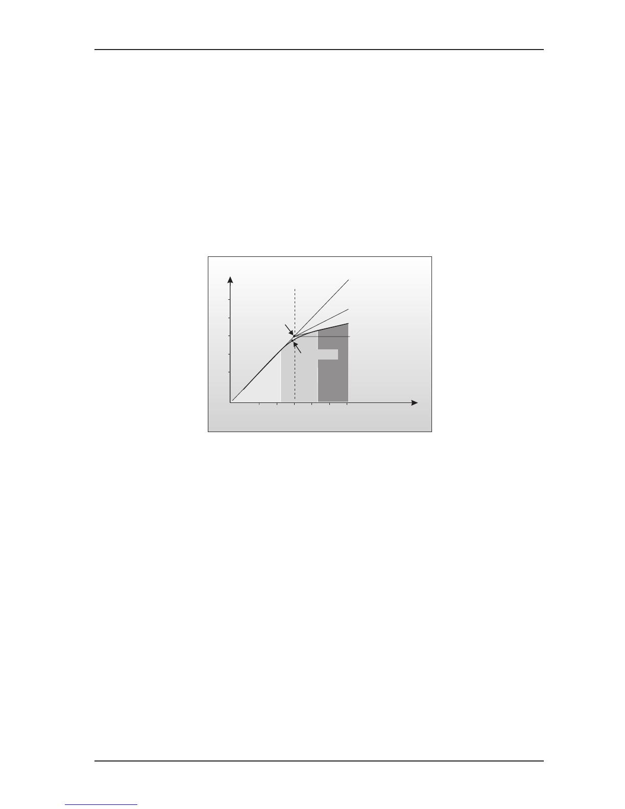
Threshold
Gain 0 dB
Input
Output
oo:1
Limiter
Ratio 2:1
Ratio 4:1
Hard Knee
IKA Curve
Fig. 5.1: IKA characteristic of the compressor section
The new IKA (Interactive Knee Adaptation) circuit prevents aggressive compression, created by high ratios,
from sounding too unnatural. This is achieved with an interactive control function, which begins above the
threshold level and introduces a Soft Knee curve characteristic in the range up to 10 dB above the threshold
point. Beyond this range, the signal is subjected to linear (Hard Knee) compression.
+ With the threshold control completely turned to the right, the threshold value is +20 dB. Since
such a value will not be reached in practice, you can use it to disable the compressor section
and work exclusively with the limiter circuits.
5. APPLICATIONS
Downloaded from www.Manualslib.com manuals search engine
18
MULTICOM PRO MDX4400
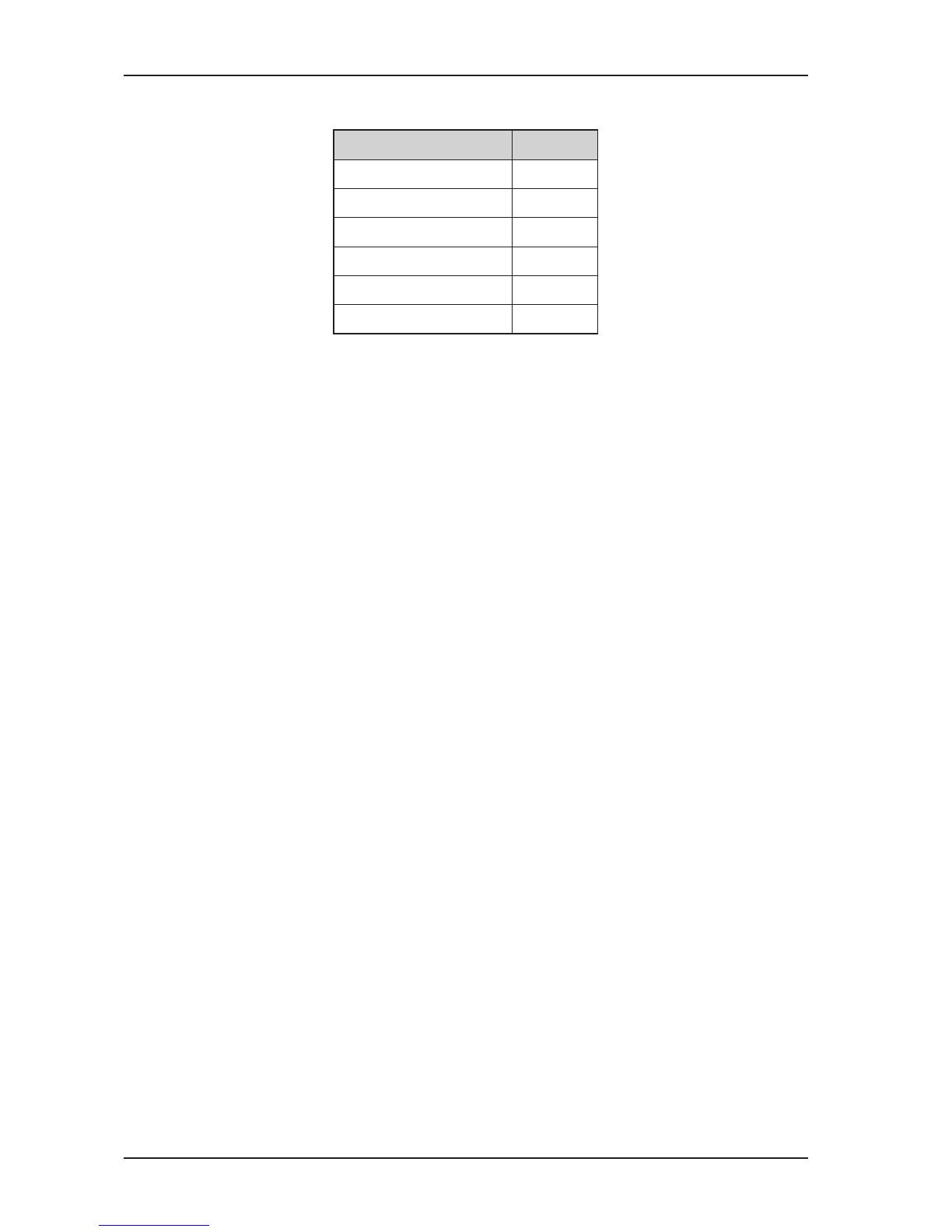
5.2.1 Initial Settings For The Compressor Section
lortnoC gnitteS
hctiwsTUO/NINI
hctiwsEVITCARETNINI
hctiwsRETLIFCSTUO
lortnocDLOHSERHTBd02+
lortnocOITAR1:3
lortnocTUPTUOBd0
Tab. 5.1: Initial settings for the compressor section
Rotate the THRESHOLD control counterclockwise until an appropriate amount of gain reduction is indicated on
the GAIN REDUCTION meter. This operation will be accompanied by an audible drop in output level. The
OUTPUT control should now be turned clockwise to reinstate the output level. The level of the unprocessed and
the processed signal can be compared by pressing the I/O METER switch and observing the INPUT/OUTPUT
LEVEL meter.
Final adjustments of the RATIO control can then be made to suit your particular requirements. The experi-
enced user will be in a position to specify parameters while in bypass mode and thus realize the effect before
the unit is actually switched into operation. This is important in live situations, where a signal needs to be
managed efficiently by the engineer, without the convenience of continual A/B comparison.
5.2.2 The MULTICOM PRO As A Sound Effects Unit
In the early 1960s, musicians began looking at the recording process as a way to create new sounds. The
pumping effect which had been avoided by earlier engineers suddenly became fashionable and was utilized as
a creative tool, laying the groundwork for many of the sounds which are now considered indispensable in
contemporary music. The compressor is used in this role because you can hear it working, and control of the
dynamic range is of secondary importance.
The BEHRINGER MULTICOM PRO, with its extensive range of functions, is well suited to this application.
Sound effects of this kind can be achieved using extreme settings. To achieve this, set the THRESHOLD
control to a fairly low level, the RATIO control to almost maximum to obtain the desired effect. Experiment with
all the controls in order to get a feel of their function!
5.2.3 The Muffling Effect Of A Compressor
Quite often, compressors are sometimes accused of muffling the sound, whilst at the same time reducing the
dynamics. This fact should be investigated further. Bass frequencies contain most of the energy within music
and therefore cause the compressor to reduce the overall dynamics. If the music also contains high frequen-
cies along with the bass frequencies, these are also reduced in level. This is the reason why: in an extremely
compressed recording of drums, the cymbals and high-hats are acoustically swamped by the sound of the
snare or the bass drum. The same effect is experienced when processing reverberated or ambient sounds. The
solution commonly used to this basic problem is either to reduce the compression ratio or to slow down the
attack time, so that the increasing high frequency transients pass through the compressor unhindered before
the compressor takes effect.
The MULTICOM PRO MDX4400 offers a solution to this problem that is by much more elegant. The SC Filter
switch allows you to activate a highpass filter in the control signal path of the compressor. This filter makes
sure that midrange and treble range frequencies are taken into account to a greater extent, and that a low-
frequency signal triggers less compression than a midrange/treble signal of comparable level. A major advan-
tage of this design can be seen in the fact that the frequency response of the overall signal is not modified
below the threshold adjusted with the Threshold control.
5. APPLICATIONS
Downloaded from www.Manualslib.com manuals search engine
19
MULTICOM PRO MDX4400
In pop music the dynamics of both kick drum and bass guitar are usually processed individually. The sidechain
filter is therefore ideally suited to apply overall compression in the mixdown, to compress the music while
increasing its loudness, but without having to accept the drawbacks described above.
Please note that we offer a whole series of high-grade equalizers and enhancers/exciters, which are perfect
tools to give any dynamics-processed signal the finishing acoustic touch. Please ask for detailed information!
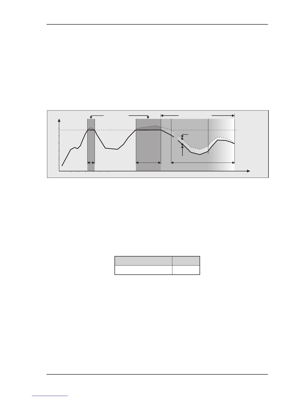
5.3 Peak Limiter Section
As a section of its own and independent of the remaining control functions, the peak limiter enables you to limit
the maximum peak level on the MULTICOM PROs output. It has been designed for use in combination with the
compressor section. Independently of all compressor functions, you can protect subsequent devices against
signal peaks, short-time overload and excess modulation (radio stations, etc.).
Output
Input
Peak Limiting
Program Limiting
Release
Threshold
t/ms
Level
20 ms
10 20 30
5 ms
approx. 1 s
Fig. 5.3: IGC characteristic of the limiter section
The diagram illustrates the functioning of the IGC limiter. The solid graph represents the output signal, while the
dashed graph above shows the input signal response. The areas between the graphs represent the amount of
gain reduction (bright areas are clipping areas, i.e. signal peaks are radically cut off, dark areas show the
effect of the program limiter). The limiter is activated when the adjusted threshold is exceeded for more than 20
ms, so as to limit audible clipping to a very short moment. About 1 s after the signals has dropped below the
threshold again, the reduction is set to 0 dB, so that input and output signals are identical again (unity gain).
5.3.1 Initial Settings For The Peak Limiter Section
lortnoC gnitteS
lortnocDLOHSERHTFFO
Tab. 5.3: Initial settings for the peak limiter section
The THRESHOLD control of the Peak Limiter sets the threshold level, so that subsequent units are protected
from overloading. If the LIM comes on regularly or is on constantly, the OUTPUT control of the compressor
section must be turned down, as this control sets the level of the signal, which is routed to the Peak Limiter
section.
If this technique leads to an undesired drop in the overall level, it is recommended that you increase the
compression: either, reduce the threshold level, or increase the compression ratio with the RATIO control. The
OUTPUT control will compensate for a renewed drop in level.
5. APPLICATIONS
Downloaded from www.Manualslib.com manuals search engine

20
MULTICOM PRO MDX4400
6. SPECIAL APPLICATIONS
6.1 Using The MULTICOM PRO For Recording And Cassette Duplication
In the recording and duplication field the goal should always be to achieve an optimum recording level onto the
recording media. Too low or too high recording levels lead to side effects such as noise, distortion etc. In
mastering and multitrack recording, as well as in duplication, one should always take care to utilize the full
dynamic range of the tape recorder, DAT recorder etc. Principally, it is possible to control the recording level by
riding faders, which means with low level signals, the gain is increased, whereas the amplitude of high level
signal is reduced. It is obvious that this method is insufficient because, especially in live recordings, the
expected signal levels cannot be anticipated correctly. Especially with multitrack recordings, which are run
under hectic circumstances, the signal level of all channels cannot be monitored and controlled at the same
time. Generally, with manual control, it is not possible to achieve satisfying recording results.
An automatic gain control system achieves better and more constant results. Use the MULTICOM PRO by
starting with the initial settings, and use its dynamic control functions in order to be able to drive an analogue,
as well as a digital recording, up to the limit of its maximum dynamic range while remaining noise- and
distortion-free.
6.1.1 The MULTICOM PRO In Digital Recording And Sampling
In an analogue recording, too low recording levels lead to an increased noise level, whereas too high levels will
cause a compressed and squashed sound. In extreme cases, it will cause distortion due to tape saturation.
In contrast to analogue, side effects in the digital field always become extremely audible: with decreasing level,
a tape previously recorded with insufficient level loses resolution: the recording sounds hard and loses
atmosphere. With excessive level, the recording sounds harsh and heavily distorted. In order to avoid these
effects, the Peak Limiter section of the MULTICOM PRO should be placed before for example a sampler. As a
result of this process, a digital recording or a sampling event can be optimally set in level without any problem.
6.1.2 The MULTICOM PRO In Mastering
The mastering process is one of the most critical processing steps in recording. In this production step, it is
the goal to achieve a maximum level copy of the recording, without any noise or distortion. In many
applications it is further required to produce a high average volume. In the field of commercial media for exam-
ple, this is apparent especially with records and cassettes which are processed with high average volumes.
Quite often in these cases, dynamics suffer drastically, because the program material has been compressed
and limited too heavily. Using the compressor and the Peak Limiter section of the MULTICOM PRO allows you
to drastically increase the overall volume, without audibly affecting the dynamics.
Proceed as follows:
1. Limit the dynamics of the program material by 6 dB using the Peak Limiter section. By softly clipping just
the transients, the real audio signal will not be limited, resulting in a higher headroom. The overall gain can
now be increased by 6 dB, which leads to a higher volume. More than 6 dB should not be limited, otherwise
side effects could become audible.
2. Therefore, in addition, you should also use compression. It is recommended that the compression is limited
to the first 6 dB of the dynamic range only. A high threshold level in addition to the auto mode will give good
results.
This effect is particularly noticeable with DAT recorders, whose level indicators achieve a response time of less
than 1 ms. Set the DAT recorder at unity and now reduce the LEVEL control of the peak limiter until the LIM
LED starts to illuminate. The cut signal peaks cause a reduced recording level of about 6 dB, which is visible
on the level indicators of the DAT recorder. Now increase the recording level of the recorder back to unity. The
result is a clearly louder recording without any loss of sound.
6.2 The MULTICOM PRO as a protective device
Sound system distortion is usually a result of amplifiers and loudspeakers being driven beyond their limitations
by signals clipping. The signal limitations that occur lead to unpleasant distortion that is dangerous to the speakers.
6. SPECIAL APPLICATIONS
Downloaded from www.Manualslib.com manuals search engine
/