
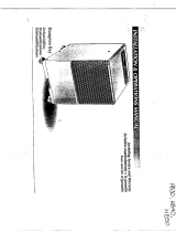
Originalinstructions
User´sManual
MK30D,MK45D,M
K60D,MK90D
Dehumidifier
Coolingunit
190TEN-1071-C1304 ©MuntersEuropeAB2013

Importantuserinformation
Intendeduseofequipment
Munters dehumidifiers are intended to be used for the
dehumidification of air. All other uses of the equipment,
or use which is contrar y to the instr uctions given in
this manual, can cause personal injury and/or machine
damage.
Warrantyando bl
igations
Thewarrantyper
iod is valid from the date the
equipment left o
ur factory, unless otherwise advised
in writing. The
warranty is limited to a free exchange
including fre
e freight of the faulty unit or components,
which have fai
led as a result of faulty quality or defects in
manufacture.
Munters guarantees that the unit supplied
has undergon
e thorough testing to ensure that it meets
the specifica
tions given here. All warranty claims must
include pro
of that the fault has occurred within the
warranty pe
riod and that the unit has been used in
accordance
with the specifications. All claims must
specify th
e unit type and manufacturing number. This
informati
on is stamped on the unit identification plate,
see the se
ction Marking.
It is a condition of the warranty that the unit for the full
warranty period is serviced and maintained by a qualified
Munters engineer or Munters approved engineer.
Access to specific and calibrated test equipment is
necessary. The service and maintenance must be
documented for the warranty to be valid.
Always
contact Munters for service or repair. Operating
faults
can occur if the unit is maintained insufficiently or
incor
rectly.
Note!
The contents of this publication can be changed without
prior notice. This publication contains information
which is protected by copyright laws. No part of this
publication may be reproduced, stored in a system for
information retrieval or be transmitted in any form, in
any manner without Munters’ written consent. Please
send any comments regarding the contents of this
publication to:
Munters E urope AB
Technical Documentation
P O Box 1150
SE - 164 26 KISTA Sweden
e-mail: t-doc@munters.se
Safety
In this publication hazardous activities are indicated and
preceded by the common hazard symbol.
WARNING!
isusedinthispu blicationtoindicateapossibleda ngerthat
couldleadtopersonalinjury. Aninstructionisnormallygiven,
followedbyashortexpl anation,plusthepossiblee ffectsif
theinstructionisnotfollowed.
CAUTION!
isusedinthispu blicationtoindicateapossibleda ngerthat
couldleadtodamagetothemachineorotherequipment
and/orcauseenvironmentaldamage. Aninstruction
isnormallygiven,followedbyashortexplanation,plus
thepossibleenvironmentaleffectiftheinstructioni snot
followed.
NOTE! Usedtoaccentuatesupplementaryinformation
thatisrequiredforproblem-freeuseoroptimaluseofthe
unit.
ii Importantuserinformation 190TEN-1071-C1304

Tableo fcontents
Importantuserinfor
mation ...............
ii
Intendeduseo fequi
pment ...........
ii
Warrantyandobligations .............
ii
Note! ...................................
ii
Safety ..................................
ii
Tableofconten
ts ...........................
iii
1 Introduction ................................. 1
1.1 General ................................
1
1.2 UnpackingoftheunitsMK30D-
MK60D .................................
1
1.3 Unpackingoftheunit(MK90D) .......
1
1.4 Marking ................................
2
1.5 Transportofthedehumid i fi er .........
3
1.6 Stacking ................................
3
1.7 Operationprinciple ....................
3
1.8 Mainc
omponents .....................
4
1.9 Watertank(MK30D-MK60D) .........
4
1.10 Driptray(MK90D) .....................
5
2 Installation ................................... 6
2.1 Electricalconnection ..................
6
2.
2
Co
nnectionofhumidistat .............
7
2.3 Remotesignals .......................
7
3 Operation .................................... 8
3.1 Controlpanel ..........................
8
3.2 Switchingon/off .......................
9
3.3 Internalhygrostatoperation ..........
10
3.4 Externalhygrostato
peration .........
10
3.5 Hourcounter ...........................
11
3.6 Displaytexts ...........................
12
3.7 Textdisplayswhennotconnectedto
mains ...................................
13
3.8 Replacingthememorybattery .......
14
3.9 Errormessages .......................
15
3.9.1 MK30D-MK60D ................
15
3.9.2 MK90D .........................
16
4 MaintenanceandService ................. 17
4.1 Monthlypreventivemaintenance
(MK30D-MK60D) .....................
17
4.2 Monthlypreventivemaintenance
(MK90D) ...............................
17
4.3 Annualpreventivemaintenance
(MK30D-MK90D) .....................
18
5 Troubleshooting ........................... 19
6 TechnicalSpecification .................... 20
6.1 DimensionsMK30D-MK60D .........
20
6.2 DimensionsMK90D ..................
20
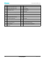
6.3 Tec
h
nicaldata .........................
21
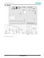
7 Wiringdiagrams ............................ 22
7.1 MK30D-MK60D .......................
22
7.2 MK90D .................................
2
4
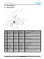
8S
parepartlists ..............................
2
6
8
.1
M
K30D-MK60D .......................
26
8.2 MK90D ................................
28
190TEN-1071-C1304 Tableofcontents iii

Dehumidifier M KD-series
1Introduction
1.1 General
The Munters MKD-series dehumidifi
ers are available in four (4) different sizes and they can easily be moved
to locations where dehumidificati
on of air is required.
WARNING!
Itistheresp onsibilityoftheoperatortorea dandunderstandthisservicemanualandothe rinform ationprovided,
andtousethecorrectoperatingprocedures.
Read the entire manual before the initial start-up of the dehumidifier. Awareness of the correct operating
procedure for the machine and its safety devices is important, to avoid damage or injury.
1.2 UnpackingoftheunitsMK30D-MK60D
WARNING!
Ifthedehumidifierha
sbeenlaiddownduringtransport,itisimperativethatyouplaceitinuprightpositionforat
least1hourbeforepu
tintoservice!
Follow these steps to unwrap the unit and make it ready for use
1 Open the cardboard box in the top
2 Tilt the box with the handle and wheels towards the floor
3 Pull the handle of the dehumidifier and wheel the dehumidifier out of the box still lying down
4 Tilt the dehumidifier to an upright position
5 Loosen the knobs, pull the handle up to the desired height and retighten the knobs
6 Remove the protective foil on the control panel
1.3 Unpacki
ngoftheunit(MK90D)
WARNING!
Ifthedehumidifierhasbeenlaiddownduringtransport,itisimperativethatyouplaceitinuprightpositionforat
least1hourbeforeputintoservice!
1Unwr
ap and lift t he box from the dehumidifier
2Li
ft the dehumidifier clear of the pallet
3C
onnect the drain outlet stub which is supplied with t he dehumidifier
1 Introduction 190TEN-1071-C1304

Dehumidifier M KD-series
1.4 Marking
MK30D-MK60D: The identification plate is placed behind the bucket inside the dehumidifier.
MK90D:The identification plate is placed at t he side of the dehumidifier
D
D
3-32
190TEN-1071-C1304 Introduction 2

Dehumidifier M KD-series
1.5 Transportofthedehumidifier
NOTE! Observelocalworkingenvironmentrulesasregardsheavylifting
Twopeopleoracranecanmovethedehumidifier. See the instructions below
2 people Hoist/crane
Lift as shown below Lifting u sing a cargo strap
The wheels are positioned such that the machine can be pulled upstairs without damage to the cabinet or
stairs.
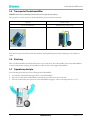
1.6 Stacking
Max. two dehumidifiers should be stacked on t op of each other. Press the handle of the lower dehumidifier
to the bottom before stacking. T he handle then fits a notch on the upper dehumidifier.
1.7 Operationprinciple
The following describes the air flow through the dehumidifier :
1. A fan draws in humid air through a filter to the dehumidifier
2. The air is cooled down and humidity/water drops are led down to the water tank
3. The air is reheated by the operation of the dehumidifier (approx. increase in temperature is +5 °C)
3 Introduction 190TEN-1071-C1304

Dehumidifier M KD-series
Due to the repeated air circulation thr
ough the dehumidifier, the air humidity is continuously reduced
whereby achieving rapid but ge ntle d
rying. The dehumidifier will operate continuously if not a humidity
sensor is connected.
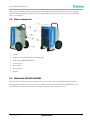
1.8 Mainc omponents
1Handle
2 Supply air inlet with PPI filter behind the grill
3 Water tank (MK30D-MK60D)
4 Control panel
5 Power cable
6Dryairoutlet
7Wheels
1.9 Watertank(MK30D-MK60D)
Water is collected in the water tank. Alternatively, you can also setup the dehumidifier for permanent
drainage with the a dapter for hose connection . When the water tank is full, the dehumidifier shuts off
automatically. Operation of the unit is not possible while the water tank is removed.
190TEN-1071-C1304 Introduction 4

Dehumidifier M KD-series
1.10 Driptray(MK90D)
The drip tray catches condensation and is fitted with an outlet branch that has a 1/2" tapping (enclosed)
5 Introduction 190TEN-1071-C1304

Dehumidifier M KD-series
2Installation
Place the dehumidifier
■ in the middle of a room if possible to ensure good air circulation
■ w here air can be sucked in freely through the fi lter and blown out on the opposite side
■ with a minimum distance on the supply air side from a wall of about 600 mm. T he minimum distance on
the dry air side should be 3 m
■ away from any source of heat e.g. a radiator
In addition, ensure that windows and doors are closed in the room to be dehumidified.
2.1 Electricalconnection
The dehumi
difier is complete with cable and plug and ready for c onnection to a 230V/50Hz socket with a
10A fuse o
r a 16A circuit breaker.
190TEN-1071-C1304 Installation 6

Dehumidifier M KD-series
2.2 Connectionofhumidistat
The connection socket for the humidistat is located at the power cable entry.
The humidistat shall be mounted 1–1.5 m. above the floor and positioned so that it is not exposed directly to
dry air from the unit or incoming moist air from opening and closing doors. It may not be placed close to a
heat source or so that it is exposed to direct sunlight. The humidistat shall be a single stage humidistat and
connected so that the controlling circuit closes as relative humidity increases. T he connecting cable shall be
screened and have copper conductors with a minimum cross-section area of 2 x 0.75 mm2.
2.3 Remotesignals
If an external alarm or run signal is required use terminal 24 and 25 which are connected by an electronic
relay. The run signal to be connected at term inal 22 and 23. If an error occurs there is no longer connection
and t he alarm will start. Max 24V DC and 1 ,5mA.
7 Installation 190TEN-1071-C1304

Dehumidifier M KD-series
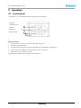
3 Operation
3.1 Controlpanel
All functions are controlled from the integrated control panel.
1Display
2 F unction keys
3 Status
indicators
4 Main switch
1
2
3
4
Main functions
■ Manual or auto operation (built-in adjustable hygrostat).
■ External hygrostat socket.
■ .Display of temperature, relative air humidity, hours and kWh consumption
■ Hour counter and kWh consumed without 230V connection.
■ Adjustable service interval counter.
Operation described in the user g uide in this manual.
190TEN-1071-C1304 Operation 8

Dehumidifier M KD-series
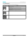
3.2 Switchingon/off
The table below shows operation of the on/offfunction and display texts
Key Display
ON constant operation
INT HYG ON operation controlled by internal hygrostat
INT HYG STOP if internal hygrostat set point is reached
EXT HYG ON operation controlled by external hygrostat
EXT H YG STOP if external hygrostat set point is reached
Switch off
The green LED indicates active dehumidification
9 Operation 190TEN-1071-C1304

Dehumidifier M KD-series
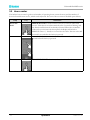
3.3 Internalhygrostatoperation
Step Key Feedback
Press and
hold
HYG SET RHxxx% - will flash for 5 seco
nds. T he dehumidifier will then
switch to internal hygrostat con
trolled operation with set point (once the
set point is reached, the displa
ywillshowINT H YG STOP).
Press +/- briefly t o set the RH% value in during the above 5 second period.
The new value will be saved after a further 5 second period after the last
key is pressed
Press HYG OFF- will flash for 5 seconds. The dehumidifier will then switch to
constant operation
3.4 Externalhygrostatoperation
If an external hygrostat is connected, the machine will automatically switch over to using it. Any adjustment
of the set point must now be made on the external hygrostat. (once the set point is reached, the display will
show EXT HYG STOP)
190TEN-1071-C1304 Operation 10

Dehumidifier M KD-series
3.5 Hourcounter
The built in hour counter logs the total number of operating hours (cannot be reset) and the number of
hours left until the next service, which can be adjusted. The service hour counter is disabled upon delivery.
Step Key Feedback
Press and
hold
SERVICE xxxxh shows the number of hours to the next authorised
serv ice. This value is saved automatically after 5 seconds of flashing, and
the function will activate if not already activated. When the set number
of hours for service intervals has expired, the display will switch to
SERV ICE. Press +/- briefly to set a new service value. The new value will
be saved 5 seconds after the last key is pressed
Press +/- briefly t o set a new service value. The new value will be saved 5
seconds after the last key is pressed
Press SET SERVICE OFF- deactivates the service timer function
11 Operation 190TEN-1071-C1304

Dehumidifier M KD-series
3.6 Displaytexts
The table below shows how to operate the operating information functions
Key Feedback
XXºCshows the current room temperature
Actual RH% shows the actual relative air humidity
value measured
XX kWh, shows total energy consumption.
Cannot be reset
xxxxh shows the t
otal number of operating hours
for the machine.
Cannot be reset
190TEN-1071-C1304 Operation 12

Dehumidifier M KD-series
3.7 Textdisplayswhennotconnectedtomains
The machine has a built-in battery to allow reading text displays when not connected to the mains. The
following texts can be read when not connected to the mains:
Key
Feedback
hold down
and
Displays total energy consum ption in kWh.
press once
hold down
Shows total number of operating hours for the dehumidifier
press once
13 Operation 190TEN-1071-C1304

Dehumidifier M KD-series
3.8 Replacingthememorybattery
If the hour counters cannot be read when disconnected from mains, it is probably due to flat memory
battery. Replacement procedure:
WARNING!
Alwaysdisconnectfromthemainsbeforechangingbattery
Action
1 Slacken the screws on both side of the
control panel, and carefully lift the
panel up using the top edge
2 Cut the cable tie holding the battery. Replace the battery, using a new cable tie max. 2.5 mm wide.
Use Alkaline AAA batteries
only Illustration of PCB with battery included in the wiring diagram
on pag
e 22.
190TEN-1071-C1304 Operation 14

Dehumidifier M KD-series
3.9 Errormessages
An overwiev of possible errors which prevent normal operation.
3.9.1 MK30D-MK60D
Errormessages Illustration Cause Remedy
Yellow light on centre
LED w ith emptying
symbol and FULL on
display.Seeemptying
guide below, or check
pump outlet
Water container is full
or fault on water pump
(accessory)
See emptying guide
below, or check pump
outlet
Red light on right
warning LED HIGH
TEMP on display
Pressure or temperature
in high pressure element
too high
Check filter and
dehumidifier for dirt
in airways
Red light on right
warning LED
AMBIENT TE M P
on display
Room temperature out
of normal range
Place the dehumidifier in
the specified temperature
range, between 3°-32ºC
SENSOR FAIL
1: EVAP FAIL
Evaporator
thermometer defective
Requires an authorised
service technician
2: COND FAIL
Condenser
thermometer defective
Requires an authorised
service technician
Red light on right
warning LED
SENSOR FAIL on
display. One of the
inter nal sensors is
defective. Use the +/-
keys to toggle between 3
possible errors
3: ROOM FAIL
The internal room
thermometer is
defective
Requires an authorised
service technician
Red light on right
warning LED LP
STOPon display
Leak in cooling circuit Requires an authorised
service techn ician
15 Operation 190TEN-1071-C1304

Dehumidifier M KD-series
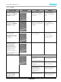
3.9.2 MK90D
Errormessages Illustration Cause Remedy
Red light on right
warning LED HIGH
TEMP on display .
Water container is full
or fault on water pump
(accessory)
See emptying guide
below, or check pump
outlet
Red light on right
warning LED HIGH
TEMP on display
Pressure or temperature
in high pressure element
too high
Check filter and
dehumidifier for dirt
in airways
Red light on right
warning LED
AMBIENT TE M P
on display
Room temperature out
of normal range
Place the dehumidifier
in the specified
temperature range,
between 3°-32°
Red light on right
warning LED
SENSOR FAIL on
display. One of the
inter nal sensors is
defective. Use the +/-
keys to toggle between 3
possible errors
SENSOR FA IL
1: EVAP FAIL
Evaporator
thermometer defective
Requires an authorised
service technician
2: COND FAIL
Condenser
thermometer defective
Requires an authorised
service technician
3: ROOM FAIL
The internal room
thermometer is
defective
Requires an authorised
service technician
Red light on right
warning LED LP
STOPon display
Leak in cooling circuit Requires an authorised
service technician
190TEN-1071-C1304 Operation 16

Dehumidifier M KD-series
4 MaintenanceandService
The unit includes mechanical and electrical parts and the unit is often placed in a rough environment where
the com ponents are exposed to different climate conditions. Therefore the unit will need preventive
maintenance on a regular basis.
Proper maintenance of the unit is necessary in order to achieve trouble-free operation. This section contains
description of the recommended monthly and annual maintenance.
CAUTION!
Alwaysdisconnectthepowerc
ablefromtheunitbeforedoinganypreventivemaintenance!
4.1 Monthlypreventivemaintenance(MK30D-MK60D)
Follow this procedure to car ry out the monthly preventive maintenance:
1 Open the front grill by tilting it outwards
2Removethefilter. Either rinse it with lukewarm soapy water or vacuumclean it if the filter is only
a little dirty. Change the filter if it is ver y dirty.
3 Clean the water tank
4 Remove the two screws in each side and tilt the jacket outwards about 30º
5 Lift t he jacket up and clear of the dehumidifier
6 Clean the evaporator coil by brushing with a soft brush and vacuum-clean/compressed air. Mount
the jacket and put the water tank back in place Note! Check that the water tank is fitted correctly
4.2 Monthlypr
eventivemaintenance(MK90D)
Follow this procedure to car ry out the monthly preventive maintenance:
1 Open the front grill by tilting it outwards
2Removethefilter. Either rinse it with lukewarm soapy water or vacuum clean it if the filter is only a
little dirty. Change the filter if it is very dir ty
3CleanthedriptrayNote !When you refit the drip tray, make sure that the back edge of the drip tray
rests on the edg e inside the dehumidifier.
4 Remove the two screws in each side and tilt the jacket outwards about 30°
5 Lift the jacket up and clear of the dehumidifier
6 Clean the evaporator coil by brushing with a soft brush and vacuum-clean/compressed air
7 Mount the jacket
17 MaintenanceandService 190TEN-1071-C1304
Page is loading ...
Page is loading ...
Page is loading ...
Page is loading ...
Page is loading ...
Page is loading ...
Page is loading ...
Page is loading ...
Page is loading ...
Page is loading ...
Page is loading ...
Page is loading ...
Page is loading ...
Page is loading ...
Page is loading ...
Page is loading ...
-
 1
1
-
 2
2
-
 3
3
-
 4
4
-
 5
5
-
 6
6
-
 7
7
-
 8
8
-
 9
9
-
 10
10
-
 11
11
-
 12
12
-
 13
13
-
 14
14
-
 15
15
-
 16
16
-
 17
17
-
 18
18
-
 19
19
-
 20
20
-
 21
21
-
 22
22
-
 23
23
-
 24
24
-
 25
25
-
 26
26
-
 27
27
-
 28
28
-
 29
29
-
 30
30
-
 31
31
-
 32
32
-
 33
33
-
 34
34
-
 35
35
-
 36
36


Ask a question and I''ll find the answer in the document
Finding information in a document is now easier with AI
Related papers
-
Munters TEN-DSC-E1708 Owner's manual
-
Munters T-M160L-A1808 Owner's manual
-
Munters T-M190Y-A1808 Owner's manual
-
-
-
-
-
-
-
Other documents
-
Aerial AD 20 Condensation Dehumidifier User manual
-
JUNG CD5201HYG Operating instructions
-
 Hampton Bay HB40-S Owner's manual
-
AlorAir ARMORED 170L Operating instructions
-
Ivation IVA-DM45 User manual
-
 Dantherm CDT 60 Condensation Dehumidifier User manual
-
Kollmorgen MKD-N Installation guide
-
-
 Dantherm CDT 30S-40S User manual
-
Siemens QFM81.2 Duct Hygrostat User manual


