Page is loading ...

PLASMA CUTTING SYSTEM
81
CUTMASTER
™
Rev. AC.01 Date: April 13, 2007 Manual # 0-2957
Operating Features:
A-04517
Service Manual


WARNINGS
Read and understand this entire Manual and your employer’s safety practices before installing, operat-
ing, or servicing the equipment.
While the information contained in this Manual represents the Manufacturer's best judgement, the
Manufacturer assumes no liability for its use.
Plasma Cutting Power Supply
CutMaster™ 81
Operating Manual Number 0-2957
Covered under U.S. Patents.
Published by:
Thermal Dynamics Corporation
82 Benning Street
West Lebanon, New Hampshire, USA 03784
(603) 298-5711
www.thermal-dynamics.com
© Copyright 2003, 2004, 2005, 2006, 2007 by
Thermal Dynamics Corporation
All rights reserved.
Reproduction of this work, in whole or in part, without written permission of the pub-
lisher is prohibited.
The publisher does not assume and hereby disclaims any liability to any party for any
loss or damage caused by any error or omission in this Manual, whether such error
results from negligence, accident, or any other cause.
Printed in the United States of America
Publication Date: April 13, 2007
Record the following information for Warranty purposes:
Where Purchased:____________________________________
Purchase Date:_______________________________________
Power Supply Serial #:________________________________
Torch Serial #:________________________________________


TABLE OF CONTENTS
SECTION 1:
GENERAL INFORMATION ................................................................................................ 1-1
1.01 Notes, Cautions and Warnings ...................................................................... 1-1
1.02 Important Safety Precautions ....................................................................... 1-1
1.03 Publications .................................................................................................. 1-2
1.04 Note, Attention et Avertissement .................................................................. 1-3
1.05 Precautions De Securite Importantes ........................................................... 1-3
1.06 Documents De Reference ............................................................................. 1-5
1.07 Declaration of Conformity ............................................................................. 1-7
1.08 Statement of Warranty .................................................................................. 1-8
SECTION 2:
INTRODUCTION ............................................................................................................... 2-1
2.01 Scope Of Manual ......................................................................................... 2-1
2.02 General Service Philosophy ......................................................................... 2-1
2.03 Service Responsibilities ............................................................................... 2-1
SECTION 3: DESCRIPTION ................................................................................................... 3-1
3.01 Scope .......................................................................................................... 3-1
3.02 Power Supply Specifications ........................................................................ 3-1
3.03 Air Regulator/Filter Assembly Specifications ................................................ 3-3
SECTION 4:
TROUBLESHOOTING ....................................................................................................... 4-1
4.01 Introduction................................................................................................... 4-1
4.02 Periodic Inspection & Cleaning Procedures ................................................... 4-1
4.03 System Theory ............................................................................................. 4-1
4.04 Common Operating Problems ....................................................................... 4-2
4.05 Troubleshooting Guide - General Information ................................................. 4-3
4.06 Circuit Fault Isolation .................................................................................... 4-4
4.07 Main Input and Internal Power Problems ....................................................... 4-5
4.08 Pilot Arc Problems.......................................................................................4-11
4.09 Main Arc Problems ...................................................................................... 4-14
4.10 Test Procedures........................................................................................... 4-15
SECTION 5:
REPLACEMENT PROCEDURES ...................................................................................... 5-1
5.01 Scope ........................................................................................................... 5-1
5.02 Anti-Static Handling Procedures ................................................................... 5-1
5.03 Parts Replacement - General Information ..................................................... 5-1
5.04 Major External Parts Replacement ............................................................... 5-2
5.05 Front Panel Parts Replacement ..................................................................... 5-3
5.06 Left Side Internal Parts Replacement ........................................................... 5-4
5.07 Rear Panel Parts Replacement ..................................................................... 5-7
5.08 Right Side Internal Parts Replacement ......................................................... 5-8

TABLE OF CONTENTS (continued)
SECTION 6:
PARTS LISTS ................................................................................................................... 6-1
6.01 Introduction ................................................................................................... 6-1
6.02 Ordering Information ..................................................................................... 6-1
6.03 Major External Replacement Parts ............................................................... 6-2
6.04 Front Panel Replacement Parts .................................................................... 6-3
6.05 Left Side Internal Component Replacement Parts ........................................ 6-4
6.06 Rear Panel Replacement Parts .................................................................... 6-6
6.07 Right Side Internal Component Replacement Parts ...................................... 6-7
6.08 Options and Accessories ............................................................................. 6-8
PATENT INFORMATION ............................................................................................................ 6-9
APPENDIX 1: INPUT WIRING REQUIREMENTS ..................................................................... A-1
APPENDIX 2: SEQUENCE OF OPERATION
(BLOCK DIAGRAM) .......................................................................................................... A-2
APPENDIX 3: LOGIC PC BOARD LAYOUT .............................................................................. A-3
APPENDIX 4: MAIN POWER PC BOARD LAYOUT .................................................................. A-4
APPENDIX 5A: MAIN PC BOARD WIRING LAYOUT - 208/230-Volt Units ................................ A-6
APPENDIX 5B: MAIN PC BOARD WIRING LAYOUT -
400-Volt, 415-Volt 460-Volt, and 600-Volt Units .................................................................. A-7
APPENDIX 6: LED/POT PC BOARD LAYOUT .......................................................................... A-8
APPENDIX 7: INPUT DIODE PC BOARD LAYOUT .................................................................. A-9
APPENDIX 8: IGBT CIRCUIT PC BOARD LAYOUT ............................................................... A-10
APPENDIX 9: OUTPUT DIODE PC BOARD LAYOUT ............................................................ A-11
APPENDIX 10: OUTPUT BOARD WIRING DIAGRAM ............................................................ A-12
APPENDIX 11: PILOT PC BOARD LAYOUT ........................................................................... A-13
APPENDIX 12: 28VAC CIRCUIT DIAGRAM ........................................................................... A-14
APPENDIX 13: DATA TAG INFORMATION ............................................................................. A-15
APPENDIX 14: TORCH PIN-OUT DIAGRAMS ......................................................................... A-16
APPENDIX 15: TORCH CONNECTION DIAGRAMS ................................................................ A-17
APPENDIX 16A: SYSTEM SCHEMATIC, 208/230-Volt Units .................................................. A-18
APPENDIX 16B: SYSTEM SCHEMATIC,
400-Volt, 415-Volt and 460-Volt Units .............................................................................. A-20
APPENDIX 16C: APPENDIX 16C: SYSTEM SCHEMATIC, 600-Volt Units ............................. A-22
APPENDIX 17: Publication History .........................................................................................
A-24
Global Customer Service Contact Information ..................................................... Inside Rear Cover

Manual 0-2957 1-1 GENERAL INFORMATION
SECTION 1:
GENERAL INFORMATION
1.01 Notes, Cautions and Warnings
Throughout this manual, notes, cautions, and warnings
are used to highlight important information. These high-
lights are categorized as follows:
NOTE
An operation, procedure, or background informa-
tion which requires additional emphasis or is help-
ful in efficient operation of the system.
CAUTION
A procedure which, if not properly followed, may
cause damage to the equipment.
WARNING
A procedure which, if not properly followed, may
cause injury to the operator or others in the oper-
ating area.
1.02 Important Safety Precautions
WARNINGS
OPERATION AND MAINTENANCE OF
PLASMA ARC EQUIPMENT CAN BE DAN-
GEROUS AND HAZARDOUS TO YOUR
HEALTH.
Plasma arc cutting produces intense electric and
magnetic emissions that may interfere with the
proper function of cardiac pacemakers, hearing
aids, or other electronic health equipment. Per-
sons who work near plasma arc cutting applica-
tions should consult their medical health profes-
sional and the manufacturer of the health
equipment to determine whether a hazard exists.
To prevent possible injury, read, understand and
follow all warnings, safety precautions and in-
structions before using the equipment. Call 1-603-
298-5711 or your local distributor if you have any
questions.
GASES AND FUMES
Gases and fumes produced during the plasma cutting
process can be dangerous and hazardous to your health.
• Keep all fumes and gases from the breathing area.
Keep your head out of the welding fume plume.
• Use an air-supplied respirator if ventilation is not
adequate to remove all fumes and gases.
• The kinds of fumes and gases from the plasma arc
depend on the kind of metal being used, coatings
on the metal, and the different processes. You must
be very careful when cutting or welding any met-
als which may contain one or more of the follow-
ing:
Antimony Chromium Mercury
Arsenic Cobalt Nickel
Barium Copper Selenium
Beryllium Lead Silver
Cadmium Manganese Vanadium
• Always read the Material Safety Data Sheets
(MSDS) that should be supplied with the material
you are using. These MSDSs will give you the in-
formation regarding the kind and amount of fumes
and gases that may be dangerous to your health.
• For information on how to test for fumes and gases
in your workplace, refer to item 1 in Subsection 1.03,
Publications in this manual.
• Use special equipment, such as water or down draft
cutting tables, to capture fumes and gases.
• Do not use the plasma torch in an area where com-
bustible or explosive gases or materials are located.
• Phosgene, a toxic gas, is generated from the vapors
of chlorinated solvents and cleansers. Remove all
sources of these vapors.
• This product, when used for welding or cutting,
produces fumes or gases which contain chemicals
known to the State of California to cause birth de-
fects and, in some cases, cancer. (California Health
& Safety Code Sec. 25249.5 et seq.)
ELECTRIC SHOCK
Electric Shock can injure or kill. The plasma arc process
uses and produces high voltage electrical energy. This
electric energy can cause severe or fatal shock to the op-
erator or others in the workplace.
• Never touch any parts that are electrically “live”
or “hot.”

GENERAL INFORMATION 1-2 Manual 0-2957
• Wear dry gloves and clothing. Insulate yourself
from the work piece or other parts of the welding
circuit.
• Repair or replace all worn or damaged parts.
• Extra care must be taken when the workplace is
moist or damp.
• Install and maintain equipment according to NEC
code, refer to item 9 in Subsection 1.03, Publica-
tions.
• Disconnect power source before performing any
service or repairs.
• Read and follow all the instructions in the Operat-
ing Manual.
FIRE AND EXPLOSION
Fire and explosion can be caused by hot slag, sparks, or
the plasma arc.
• Be sure there is no combustible or flammable ma-
terial in the workplace. Any material that cannot
be removed must be protected.
• Ventilate all flammable or explosive vapors from
the workplace.
• Do not cut or weld on containers that may have
held combustibles.
• Provide a fire watch when working in an area where
fire hazards may exist.
• Hydrogen gas may be formed and trapped under
aluminum workpieces when they are cut under-
water or while using a water table. DO NOT cut
aluminum alloys underwater or on a water table
unless the hydrogen gas can be eliminated or dis-
sipated. Trapped hydrogen gas that is ignited will
cause an explosion.
NOISE
Noise can cause permanent hearing loss. Plasma arc pro-
cesses can cause noise levels to exceed safe limits. You
must protect your ears from loud noise to prevent per-
manent loss of hearing.
• To protect your hearing from loud noise, wear pro-
tective ear plugs and/or ear muffs. Protect others
in the workplace.
• Noise levels should be measured to be sure the deci-
bels (sound) do not exceed safe levels.
• For information on how to test for noise, see item 1
in Subsection 1.03, Publications, in this manual.
PLASMA ARC RAYS
Plasma Arc Rays can injure your eyes and burn your skin.
The plasma arc process produces very bright ultra violet
and infra red light. These arc rays will damage your
eyes and burn your skin if you are not properly protected.
• To protect your eyes, always wear a welding hel-
met or shield. Also always wear safety glasses with
side shields, goggles or other protective eye wear.
• Wear welding gloves and suitable clothing to pro-
tect your skin from the arc rays and sparks.
• Keep helmet and safety glasses in good condition.
Replace lenses when cracked, chipped or dirty.
• Protect others in the work area from the arc rays.
Use protective booths, screens or shields.
• Use the shade of lens as suggested in the following
per ANSI/ASC Z49.1:
Minimum Protective Suggested
Arc Current Shade No. Shade No.
Less Than 300* 8 9
300 - 400* 9 12
400 - 800* 10 14
* These values apply where the actual arc is clearly
seen. Experience has shown that lighter filters
may be used when the arc is hidden by the work-
piece.
1.03 Publications
Refer to the following standards or their latest revisions
for more information:
1. OSHA, SAFETY AND HEALTH STANDARDS, 29CFR
1910, obtainable from the Superintendent of Docu-
ments, U.S. Government Printing Office, Washington,
D.C. 20402
2. ANSI Standard Z49.1, SAFETY IN WELDING AND
CUTTING, obtainable from the American Welding So-
ciety, 550 N.W. LeJeune Rd, Miami, FL 33126
3. NIOSH, SAFETY AND HEALTH IN ARC WELDING
AND GAS WELDING AND CUTTING, obtainable
from the Superintendent of Documents, U.S. Govern-
ment Printing Office, Washington, D.C. 20402
4. ANSI Standard Z87.1, SAFE PRACTICES FOR OCCU-
PATION AND EDUCATIONAL EYE AND FACE PRO-
TECTION, obtainable from American National Stan-
dards Institute, 1430 Broadway, New York, NY 10018
5. ANSI Standard Z41.1, STANDARD FOR MEN’S
SAFETY-TOE FOOTWEAR, obtainable from the Ameri-
can National Standards Institute, 1430 Broadway, New
York, NY 10018

Manual 0-2957 1-3 GENERAL INFORMATION
6. ANSI Standard Z49.2, FIRE PREVENTION IN THE USE
OF CUTTING AND WELDING PROCESSES, obtain-
able from American National Standards Institute, 1430
Broadway, New York, NY 10018
7. AWS Standard A6.0, WELDING AND CUTTING CON-
TAINERS WHICH HAVE HELD COMBUSTIBLES, ob-
tainable from American Welding Society, 550 N.W.
LeJeune Rd, Miami, FL 33126
8. NFPA Standard 51, OXYGEN-FUEL GAS SYSTEMS
FOR WELDING, CUTTING AND ALLIED PRO-
CESSES, obtainable from the National Fire Protection
Association, Batterymarch Park, Quincy, MA 02269
9. NFPA Standard 70, NATIONAL ELECTRICAL CODE,
obtainable from the National Fire Protection Associa-
tion, Batterymarch Park, Quincy, MA 02269
10. NFPA Standard 51B, CUTTING AND WELDING PRO-
CESSES, obtainable from the National Fire Protection
Association, Batterymarch Park, Quincy, MA 02269
11. CGA Pamphlet P-1, SAFE HANDLING OF COM-
PRESSED GASES IN CYLINDERS, obtainable from the
Compressed Gas Association, 1235 Jefferson Davis
Highway, Suite 501, Arlington, VA 22202
12. CSA Standard W117.2, CODE FOR SAFETY IN WELD-
ING AND CUTTING, obtainable from the Canadian
Standards Association, Standards Sales, 178 Rexdale
Boulevard, Rexdale, Ontario, Canada M9W 1R3
13. NWSA booklet, WELDING SAFETY BIBLIOGRAPHY
obtainable from the National Welding Supply Associa-
tion, 1900 Arch Street, Philadelphia, PA 19103
14. American Welding Society Standard AWSF4.1, RECOM-
MENDED SAFE PRACTICES FOR THE PREPARA-
TION FOR WELDING AND CUTTING OF CONTAIN-
ERS AND PIPING THAT HAVE HELD HAZARDOUS
SUBSTANCES, obtainable from the American Welding
Society, 550 N.W. LeJeune Rd, Miami, FL 33126
15. ANSI Standard Z88.2, PRACTICE FOR RESPIRATORY
PROTECTION, obtainable from American National
Standards Institute, 1430 Broadway, New York, NY
10018
1.04 Note, Attention et
Avertissement
Dans ce manuel, les mots “note,” “attention,” et
“avertissement” sont utilisés pour mettre en relief des
informations à caractère important. Ces mises en relief
sont classifiées comme suit :
NOTE
Toute opération, procédure ou renseignement
général sur lequel il importe d’insister davantage
ou qui contribue à l’efficacité de fonctionnement
du système.
ATTENTION
Toute procédure pouvant résulter
l’endommagement du matériel en cas de non-
respect de la procédure en question.
AVERTISSEMENT
Toute procédure pouvant provoquer des blessures
de l’opérateur ou des autres personnes se trouvant
dans la zone de travail en cas de non-respect de la
procédure en question.
1.05 Precautions De Securite
Importantes
AVERTISSEMENTS
L’OPÉRATION ET LA MAINTENANCE DU
MATÉRIEL DE SOUDAGE À L’ARC AU JET
DE PLASMA PEUVENT PRÉSENTER DES
RISQUES ET DES DANGERS DE SANTÉ.
Coupant à l’arc au jet de plasma produit de l’énergie
électrique haute tension et des émissions
magnétique qui peuvent interférer la fonction
propre d’un “pacemaker” cardiaque, les appareils
auditif, ou autre matériel de santé electronique.
Ceux qui travail près d’une application à l’arc au
jet de plasma devrait consulter leur membre
professionel de médication et le manufacturier de
matériel de santé pour déterminer s’il existe des
risques de santé.
Il faut communiquer aux opérateurs et au person-
nel TOUS les dangers possibles. Afin d’éviter les
blessures possibles, lisez, comprenez et suivez tous
les avertissements, toutes les précautions de sécurité
et toutes les consignes avant d’utiliser le matériel.
Composez le + 603-298-5711 ou votre distributeur
local si vous avez des questions.
FUMÉE et GAZ
La fumée et les gaz produits par le procédé de jet de
plasma peuvent présenter des risques et des dangers de
santé.

GENERAL INFORMATION 1-4 Manual 0-2957
• Eloignez toute fumée et gaz de votre zone de respira-
tion. Gardez votre tête hors de la plume de fumée
provenant du chalumeau.
• Utilisez un appareil respiratoire à alimentation en air
si l’aération fournie ne permet pas d’éliminer la fumée
et les gaz.
• Les sortes de gaz et de fumée provenant de l’arc de
plasma dépendent du genre de métal utilisé, des
revêtements se trouvant sur le métal et des différents
procédés. Vous devez prendre soin lorsque vous
coupez ou soudez tout métal pouvant contenir un ou
plusieurs des éléments suivants:
antimoine cadmium mercure
argent chrome nickel
arsenic cobalt plomb
baryum cuivre sélénium
béryllium manganèse vanadium
• Lisez toujours les fiches de données sur la sécurité
des matières (sigle américain “MSDS”); celles-ci
devraient être fournies avec le matériel que vous
utilisez. Les MSDS contiennent des renseignements
quant à la quantité et la nature de la fumée et des gaz
pouvant poser des dangers de santé.
• Pour des informations sur la manière de tester la
fumée et les gaz de votre lieu de travail, consultez
l’article 1 et les documents cités à la page 5.
• Utilisez un équipement spécial tel que des tables de
coupe à débit d’eau ou à courant descendant pour
capter la fumée et les gaz.
• N’utilisez pas le chalumeau au jet de plasma dans une
zone où se trouvent des matières ou des gaz combus-
tibles ou explosifs.
• Le phosgène, un gaz toxique, est généré par la fumée
provenant des solvants et des produits de nettoyage
chlorés. Eliminez toute source de telle fumée.
• Ce produit, dans le procéder de soudage et de coupe,
produit de la fumée ou des gaz pouvant contenir des
éléments reconnu dans L’état de la Californie, qui
peuvent causer des défauts de naissance et le cancer.
(La sécurité de santé en Californie et la code sécurité
Sec. 25249.5 et seq.)
CHOC ELECTRIQUE
Les chocs électriques peuvent blesser ou même tuer. Le
procédé au jet de plasma requiert et produit de l’énergie
électrique haute tension. Cette énergie électrique peut
produire des chocs graves, voire mortels, pour l’opérateur
et les autres personnes sur le lieu de travail.
• Ne touchez jamais une pièce “sous tension” ou “vive”;
portez des gants et des vêtements secs. Isolez-vous
de la pièce de travail ou des autres parties du circuit
de soudage.
• Réparez ou remplacez toute pièce usée ou
endommagée.
• Prenez des soins particuliers lorsque la zone de tra-
vail est humide ou moite.
• Montez et maintenez le matériel conformément au
Code électrique national des Etats-Unis. (Voir la page
5, article 9.)
• Débranchez l’alimentation électrique avant tout tra-
vail d’entretien ou de réparation.
• Lisez et respectez toutes les consignes du Manuel de
consignes.
INCENDIE ET EXPLOSION
Les incendies et les explosions peuvent résulter des scories
chaudes, des étincelles ou de l’arc de plasma. Le procédé
à l’arc de plasma produit du métal, des étincelles, des
scories chaudes pouvant mettre le feu aux matières com-
bustibles ou provoquer l’explosion de fumées
inflammables.
• Soyez certain qu’aucune matière combustible ou in-
flammable ne se trouve sur le lieu de travail. Protégez
toute telle matière qu’il est impossible de retirer de la
zone de travail.
• Procurez une bonne aération de toutes les fumées
inflammables ou explosives.
• Ne coupez pas et ne soudez pas les conteneurs ayant
pu renfermer des matières combustibles.
• Prévoyez une veille d’incendie lors de tout travail dans
une zone présentant des dangers d’incendie.
• Le gas hydrogène peut se former ou s’accumuler sous
les pièces de travail en aluminium lorsqu’elles sont
coupées sous l’eau ou sur une table d’eau. NE PAS
couper les alliages en aluminium sous l’eau ou sur
une table d’eau à moins que le gas hydrogène peut
s’échapper ou se dissiper. Le gas hydrogène accumulé
explosera si enflammé.
RAYONS D’ARC DE PLASMA
Les rayons provenant de l’arc de plasma peuvent blesser
vos yeux et brûler votre peau. Le procédé à l’arc de
plasma produit une lumière infra-rouge et des rayons

Manual 0-2957 1-5 GENERAL INFORMATION
ultra-violets très forts. Ces rayons d’arc nuiront à vos
yeux et brûleront votre peau si vous ne vous protégez
pas correctement.
• Pour protéger vos yeux, portez toujours un casque ou
un écran de soudeur. Portez toujours des lunettes de
sécurité munies de parois latérales ou des lunettes de
protection ou une autre sorte de protection oculaire.
• Portez des gants de soudeur et un vêtement protecteur
approprié pour protéger votre peau contre les
étincelles et les rayons de l’arc.
• Maintenez votre casque et vos lunettes de protection
en bon état. Remplacez toute lentille sale ou
comportant fissure ou rognure.
• Protégez les autres personnes se trouvant sur la zone
de travail contre les rayons de l’arc en fournissant des
cabines ou des écrans de protection.
• Utilisez la nuance de lentille qui est suggèrée dans le
recommendation qui suivent ANSI/ASC Z49.1:
Nuance Minimum Nuance Suggerée
Courant Arc Protective Numéro Numéro
Moins de 300* 8 9
300 - 400* 9 12
400 - 800* 10 14
* Ces valeurs s’appliquent ou l’arc actuel est observé
clairement. L’experience a démontrer que les filtres
moins foncés peuvent être utilisés quand l’arc est
caché par moiceau de travail.
BRUIT
Le bruit peut provoquer une perte permanente de l’ouïe.
Les procédés de soudage à l’arc de plasma peuvent
provoquer des niveaux sonores supérieurs aux limites
normalement acceptables. Vous dú4ez vous protéger les
oreilles contre les bruits forts afin d’éviter une perte
permanente de l’ouïe.
• Pour protéger votre ouïe contre les bruits forts, portez
des tampons protecteurs et/ou des protections
auriculaires. Protégez également les autres personnes
se trouvant sur le lieu de travail.
• Il faut mesurer les niveaux sonores afin d’assurer que
les décibels (le bruit) ne dépassent pas les niveaux
sûrs.
• Pour des renseignements sur la manière de tester le
bruit, consultez l’article 1, page 5.
1.06 Documents De Reference
Consultez les normes suivantes ou les révisions les plus
récentes ayant été faites à celles-ci pour de plus amples
renseignements :
1. OSHA, NORMES DE SÉCURITÉ DU TRAVAIL ET DE
PROTECTION DE LA SANTÉ, 29CFR 1910,
disponible auprès du Superintendent of Documents,
U.S. Government Printing Office, Washington, D.C.
20402
2. Norme ANSI Z49.1, LA SÉCURITÉ DES
OPÉRATIONS DE COUPE ET DE SOUDAGE,
disponible auprès de la Société Américaine de
Soudage (American Welding Society), 550 N.W.
LeJeune Rd., Miami, FL 33126
3. NIOSH, LA SÉCURITÉ ET LA SANTÉ LORS DES
OPÉRATIONS DE COUPE ET DE SOUDAGE À
L’ARC ET AU GAZ, disponible auprès du Superin-
tendent of Documents, U.S. Government Printing
Office, Washington, D.C. 20402
4. Norme ANSI Z87.1, PRATIQUES SURES POUR LA
PROTECTION DES YEUX ET DU VISAGE AU TRA-
VAIL ET DANS LES ECOLES, disponible de l’Institut
Américain des Normes Nationales (American Na-
tional Standards Institute), 1430 Broadway, New York,
NY 10018
5. Norme ANSI Z41.1, NORMES POUR LES
CHAUSSURES PROTECTRICES, disponible auprès
de l’American National Standards Institute, 1430
Broadway, New York, NY 10018
6. Norme ANSI Z49.2, PRÉVENTION DES INCENDIES
LORS DE L’EMPLOI DE PROCÉDÉS DE COUPE ET
DE SOUDAGE, disponible auprès de l’American Na-
tional Standards Institute, 1430 Broadway, New York,
NY 10018
7. Norme A6.0 de l’Association Américaine du Soudage
(AWS), LE SOUDAGE ET LA COUPE DE
CONTENEURS AYANT RENFERMÉ DES PRODUITS
COMBUSTIBLES, disponible auprès de la American
Welding Society, 550 N.W. LeJeune Rd., Miami, FL
33126
8. Norme 51 de l’Association Américaine pour la Pro-
tection contre les Incendies (NFPA), LES SYSTEMES
À GAZ AVEC ALIMENTATION EN OXYGENE
POUR LE SOUDAGE, LA COUPE ET LES
PROCÉDÉS ASSOCIÉS, disponible auprès de la Na-
tional Fire Protection Association, Batterymarch Park,
Quincy, MA 02269

GENERAL INFORMATION 1-6 Manual 0-2957
9. Norme 70 de la NFPA, CODE ELECTRIQUE NA-
TIONAL, disponible auprès de la National Fire Pro-
tection Association, Batterymarch Park, Quincy, MA
02269
10. Norme 51B de la NFPA, LES PROCÉDÉS DE
COUPE ET DE SOUDAGE, disponible auprès de la
National Fire Protection Association, Batterymarch
Park, Quincy, MA 02269
11. Brochure GCA P-1, LA MANIPULATION SANS
RISQUE DES GAZ COMPRIMÉS EN CYLINDRES,
disponible auprès de l’Association des Gaz
Comprimés (Compressed Gas Association), 1235
Jefferson Davis Highway, Suite 501, Arlington, VA
22202
12. Norme CSA W117.2, CODE DE SÉCURITÉ POUR
LE SOUDAGE ET LA COUPE, disponible auprès
de l’Association des Normes Canadiennes, Stan-
dards Sales, 178 Rexdale Boulevard, Rexdale,
Ontario, Canada, M9W 1R3
13. Livret NWSA, BIBLIOGRAPHIE SUR LA
SÉCURITÉ DU SOUDAGE, disponible auprès de
l’Association Nationale de Fournitures de Soudage
(National Welding Supply Association), 1900 Arch
Street, Philadelphia, PA 19103
14. Norme AWSF4.1 de l’Association Américaine de
Soudage, RECOMMANDATIONS DE PRATIQUES
SURES POUR LA PRÉPARATION À LA COUPE ET
AU SOUDAGE DE CONTENEURS ET TUYAUX
AYANT RENFERMÉ DES PRODUITS
DANGEREUX , disponible auprès de la American
Welding Society, 550 N.W. LeJeune Rd., Miami, FL
33126
15. Norme ANSI Z88.2, PRATIQUES DE PROTECTION
RESPIRATOIRE, disponible auprès de l’American
National Standards Institute, 1430 Broadway, New
York, NY 10018

Manual 0-2957 1-7 GENERAL INFORMATION
1.07 Declaration of Conformity
Manufacturer: Thermal Dynamics Corporation
Address: 82 Benning Street
West Lebanon, New Hampshire 03784
USA
The equipment described in this manual conforms to all applicable aspects and regulations of the ‘Low Voltage Directive’
(European Council Directive 73/23/EEC as amended by Council Directive 93/68/EEC) and to the National legislation for
the enforcement of this Directive.
The equipment described in this manual conforms to all applicable aspects and regulations of the "EMC Directive" (Euro-
pean Council Directive 89/336/EEC) and to the National legislation for the enforcement of this Directive.
Serial numbers are unique with each individual piece of equipment and details description, parts used to manufacture a unit
and date of manufacture.
National Standard and Technical Specifications
The product is designed and manufactured to a number of standards and technical requirements. Among them are:
* CSA (Canadian Standards Association) standard C22.2 number 60 for Arc welding equipment.
* UL (Underwriters Laboratory) rating 94VO flammability testing for all printed-circuit boards used.
* CENELEC EN50199 EMC Product Standard for Arc Welding Equipment.
* ISO/IEC 60974-1 (BS 638-PT10) (EN 60 974-1) (EN50192) (EN50078) applicable to plasma cutting equipment and associ-
ated accessories.
* For environments with increased hazard of electrical shock, Power Supplies bearing the
S
mark conform to EN50192
when used in conjunction with hand torches with exposed cutting tips, if equipped with properly installed standoff guides.
* Extensive product design verification is conducted at the manufacturing facility as part of the routine design and manufac-
turing process. This is to ensure the product is safe, when used according to instructions in this manual and related
industry standards, and performs as specified. Rigorous testing is incorporated into the manufacturing process to ensure
the manufactured product meets or exceeds all design specifications.
Thermal Dynamics has been manufacturing products for more than 30 years, and will continue to achieve excellence in our
area of manufacture.
Manufacturers responsible representative: Steve Ward
Operations Director
Thermadyne Europe
Europa Building
Chorley N Industrial Park
Chorley, Lancashire,
England PR6 7BX

GENERAL INFORMATION 1-8 Manual 0-2957
1.08 Statement of Warranty
LIMITED WARRANTY: Subject to the terms and conditions established below, Thermal Dynamics
®
Corporation warrants to the original
retail purchaser that new Thermal Dynamics CUTMASTER™ 1Series plasma cutting systems sold after the effective date of this warranty
are free of defects in material and workmanship. Should any failure to conform to this warranty appear within the applicable period stated
below, Thermal Dynamics Corporation shall, upon notification thereof and substantiation that the product has been stored operated and
maintained in accordance with Thermal Dynamics’ specifications, instructions, recommendations and recognized industry practice, correct
such defects by suitable repair or replacement.
This warranty is exclusive and in lieu of any warranty of merchantability or fitness for a particular purpose.
Thermal Dynamics will repair or replace, at its discretion, any warranted parts or components that fail due to defects in material or
workmanship within the time periods set out below. Thermal Dynamics Corporation must be notified within 30 days of any failure, at
which time Thermal Dynamics Corporation will provide instructions on the warranty procedures to be implemented.
Thermal Dynamics Corporation will honor warranty claims submitted within the warranty periods listed below. All warranty periods
begin on the date of sale of the product to the original retail customer or 1 year after sale to an authorized Thermal Dynamics Distributor.
LIMITED WARRANTY PERIOD
Product
Power Supply Components
(Parts and Labor)
Torch and Leads
(Parts and Labor)
CUTMASTER™ 51 3 Years 1 Year
CUTMASTER™ 81 3 Years 1 Year
CUTMASTER™ 101 3 Years 1 Year
This warranty does not apply to:
1. Consumable Parts, such as tips, electrodes, shield cups, o - rings, starter cartridges, gas distributors, fuses, filters.
2. Equipment that has been modified by an unauthorized party, improperly installed, improperly operated or misused
based upon industry standards.
In the event of a claim under this warranty, the remedies shall be, at the discretion of Thermal Dynamics Corporation:
1. Repair of the defective product.
2. Replacement of the defective product.
3. Reimbursement of reasonable costs of repair when authorized in advance by Thermal Dynamics.
4. Payment of credit up to the purchase price less reasonable depreciation based on actual use.
These remedies may be authorized by Thermal Dynamics and are FOB West Lebanon, NH or an authorized Thermadyne service station.
Product returned for service is at the owner’s expense and no reimbursement of travel or transportation is authorized.
LIMITATION OF LIABILITY: Thermal Dynamics Corporation shall not under any circumstances be liable for special or consequential
damages such as, but not limited to, damage or loss of purchased or replacement goods or claims of customer of distributors (hereinafter
“Purchaser”) for service interruption. The remedies of the Purchaser set forth herein are exclusive and the liability of Thermal Dynamics
with respect to any contract, or anything done in connection therewith such as the performance or breach thereof, or from the manufacture,
sale, delivery, resale, or use of the goods covered by or furnished by Thermal Dynamics whether arising out of contract, negligence,
strict tort, or under any warranty, or otherwise, shall not, except as expressly provided herein, exceed the price of the goods upon which
liability is based.
This warranty becomes invalid if replacement parts or accessories are used which may impair the safety or performance of any
Thermal Dynamics product.
This warranty is invalid if the Thermal Dynamics product is sold by non - authorized persons.
Effective May 23, 2005

Manual 0-2957 2-1 INTRODUCTION
This Service Manual covers all types. Particular attention
is required in the Trouble-Shooting Section (Section 4) to
ensure that the technician selects the proper test points
and measurements for the Power Supply being serviced.
2.02 General Service Philosophy
Several key points are essential to properly support the
application and operation of this equipment.
A. Application
The equipment should satisfy the customer’s require-
ments as supplied and as described in Section 3 of this
manual. Be sure to confirm that the equipment is capable
of the application desired.
B. Modifications
No physical or electrical modifications other than selec-
tion of standard options and Accessories are to be made
to this equipment.
C. Customer/Operator Responsibilities
It is the customer/operator's responsibility to maintain
the equipment and peripheral accessories provided by
Thermal Dynamics in good operating order in accordance
with the procedures outlined in the operating manual,
and to protect the equipment from accidental or mali-
cious damage.
D. Repair Restrictions
The electronics consists of Printed Circuit Board (PCB)
Assemblies which must be carefully handled and must
be replaced as units. No replacement of printed circuit
solder-mounted components is allowed except as noted
in this manual.
Printed Circuit Board Assemblies to be returned must be
properly packaged in protective material and returned
intact per normal procedures.
2.03 Service Responsibilities
The service technician should be familiar with the equip-
ment and its capabilities and should be prepared to rec-
ommend arrangements of components which will pro-
vide the most efficient layout, utilizing the equipment to
its best possible advantage.
Maintenance work should be accomplished in a timely
manner. If problems are encountered, or the equip-
ment does not function as specified, contact the Tech-
nical Services Department at West Lebanon, NH for
assistance (1-603-298-5711).
SECTION 2:
INTRODUCTION
2.01 Scope Of Manual
This manual provides service instructions for Thermal
Dynamics CutMaster™ 81 Plasma Cutting Power Sup-
ply. Information in this manual is particularly applicable
to the troubleshooting and repair of this power supply,
and is intended for use by properly-trained service tech-
nicians familiar with this equipment.
For setup of this equipment, individual operating proce-
dures, and basic troubleshooting, refer to Operating
Manual (0-2956).
Read both the operating manual and the service manual
thoroughly. A complete understanding of the capabili-
ties and functions of this equipment will assure obtain-
ing the performance for which it was designed.
The CutMaster™ 81 Power Supply is available for the
following input voltages:
• 208/230-Volt Single-Phase
• 400-Volt Three-Phase
• 415-Volt Three Phase
• 460-Volt Three-Phase
• 600-Volt Three-Phase
The 460-Volt Three-Phase unit may be converted for Single-
Phase input power with a change of input power cord.

INTRODUCTION 2-2 Manual 0-2957
This Page Left Blank

Manual 0-2957 3-1 DESCRIPTION
SECTION 3: DESCRIPTION
3.01 Scope
The purpose of this section is:
• To familiarize the service technician with the capabilities and limitations of the equipment;
• To provide an overall understanding which will allow the technician, in turn, to properly train customer oper-
ating personnel.
The power supply includes all control circuitry, electrical and air inputs and outputs, pilot circuitry, work cable with
clamp, and input power cable.
3.02 Power Supply Specifications
Input Power Cable
Output Current
Power Supply Gas Filtering Ability
Ambient Temperature
IEC
Rating
TDC
Rating
IEC
Rating
TDC
Rating
IEC
Rating
TDC
Rating
Duty Cycle
Current 60A 60A 60A 60A 45A 45A
DC Voltage 104V 109V 104V 109V 98V 98V
Duty Cycle
Current 60A n/a 60A n/a 45A n/a
DC Voltage 104V n/a 104V n/a 98V n/a
Duty Cycle
Current 60A 60A 60A 60A 43A 43A
DC Voltage 104V 109V 104V 109V 97V 97V
400V and 415V Units
600V Units
Input Power
40° C (104° F)
20 - 60 Amps, Continuously Adjustable
Particulates to 20 Microns
CutMaster 81 Power Supply Duty Cycle*
50
%
460 VAC (414 - 506 VAC), Three Phase, 60 Hz
600 VAC (517 - 632 VAC), Three Phase, 60 hz
Cable for 208/230 VAC unit includes plug.
415 VAC (370 - 460 VAC), CE Three Phase, 50 Hz
CutMaster 81 Power Supply Specifications
208 / 230 VAC (187 - 253 VAC), Single Phase, 50/60 Hz
400 VAC (360 - 440 VAC), Three Phase, 50/60 Hz
460 VAC (414 - 506 VAC), Single Phase, 60 Hz
60% 100%
* NOTE: The duty cycle will be reduced if the primary input power (AC)
50
%
60% 100%
50
%
60% 100%
208/230V
and 460V Units
NOTE:
IEC Rating is determined as specified by the International Electro-Technical Commission. These specifications
include calculating an output voltage based upon power supply rated current. To facilitate comparison between
power supplies, all manufacturers use this output voltage to determine duty cycle.
TDC Rating is determined using an output voltage representative of actual output voltage during cutting with a
TDC torch. This voltage may be more or less than IEC voltage, depending upon choice of torch, consumables, and
actual cutting operation.

DESCRIPTION 3-2 Manual 0-2957
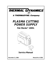
Art # A-03578
Work Cable
and Clamp
Handle and Leads Wrap
Torch Leads Receptacle
Control Panel
Art # A-03738
Input Power Cord
Ports for Optional Automation
Interface Cable
Gas Inlet Port
Gas Pressure Regulator /
Filter Assembly
Gas Pressure Gauge

Manual 0-2957 3-3 DESCRIPTION
1. Front Panel Controls and Features
• Main Power ON
/ OFF Switch
• RUN
/RAPID AUTO RESTART SET Switch
• Output Current Control (A) Sets output current for drag cutting (up to 40 Amps for drag cutting, with the
torch tip in contact with the workpiece, or for standoff cutting (up to 60 amps).
2. Front Panel Indicators
• AC When lighted, indicates AC input power is present in thepower supply.
• TEMP When lighted, indicates the power supply is overheated.
• GAS When lighted, indicates that adequate input air pressure for power supply operation is present.
• DC When lighted, indicates that power supply output circuits are active.
NOTE
Minimum pressure for power supply operation is lower than minimum pressure for torch operation.
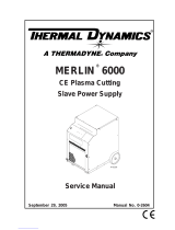
3. Dimensions and Weight
A-03572
27.5 in / 696 mm
12.4 in /
315 mm
17.3 in /
439 mm
83 lb / 37.6 kg
3.03 Air Regulator/Filter Assembly Specifications
The following specifications apply to the Air Regulator/Filter Assembly only:
1. Operating Pressure
65 psi (4.5 bar)
2. Maximum input air supply pressure
125 psi (8.6 bar)

DESCRIPTION 3-4 Manual 0-2957
This Page Left Blank
/