XPert
™
Filtered Balance Systems &
XPert
™
Filtered Balance Stations
User’s Manual
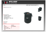
Labconco’s Mascot,
Labby the LABster
Models
3940200, 3940201, 3940202, 3940220, 3940221,
3940222, 3940300, 3940301, 3940302, 3940320,
3940321, 3940322, 3940400, 3940401, 3940402,
3940420, 3940421, 3940422
3950200, 3950201, 3950202, 3950220, 3950221,
3950222, 3950300, 3950301, 3950302, 3950320,
3950321, 3950322, 3950400, 3950401, 3950402,
3950420, 3950421, 3950422

For more information, please contact us:
ExpotechUSA
10700 Rockley Road
Houston, Texas 77099
USA
281-496-0900 [voice]
281-496-0400 [fax]
E-mail: [email protected]
Website: www.ExpotechUSA.com

Labconco XPert Filtered Balance System/Station Manual
Warranty
Labconco provides a warranty on all parts and factory workmanship. The warranty includes areas of
defective material and workmanship, provided such defect results from normal and proper use of the
equipment.
The warranty for all Labconco products will expire one year from date of installation or two years from
date of shipment from Labconco, whichever is sooner, except the following:
• Purifier® Delta® Series Biological Safety Cabinets and PuriCare® Animal Laboratory Research
Enclosures carry a three-year warranty from date of installation or four years from date of
shipment from Labconco, whichever is sooner.
• Carts carry a lifetime warranty.
• Glassware is not warranted from breakage when dropped or mishandled.
This limited warranty covers parts and labor, but not transportation and insurance charges. In the event of a
warranty claim, contact Labconco Corporation or the dealer who sold you the product. If the cause is
determined to be a manufacturing fault, the dealer or Labconco Corporation will repair or replace all
defective parts to restore the unit to operation. Under no circumstances shall Labconco Corporation be
liable for indirect, consequential, or special damages of any kind. This statement may be altered by a
specific published amendment. No individual has authorization to alter the provisions of this warranty
policy or its amendments. Lamps and filters are not covered by this warranty. Damage due to corrosion or
accidental breakage is also not covered.
Limitation of Liability
The disposal and/or emission of substances used in connection with this equipment may be governed by
various federal, state, or local regulations. All users of this equipment are required to become familiar with
any regulations that apply in the user’s area concerning the dumping of waste materials in or upon water,
land, or air and to comply with such regulations. Labconco Corporation is held harmless with respect to
user’s compliance with such regulations.
.
Part #3905501, Rev. B
ECO C695

T
T
A
A
B
B
L
L
E
E
O
O
F
F
C
C
O
O
N
N
T
T
E
E
N
N
T
T
S
S
CHAPTER 1: INTRODUCTION 1
About This Manual 3
Typographical Conventions 4
CHAPTER 2: PREREQUISITES 5
Support, Vibration & Movement Requirements 6
Temperature Variation Requirements 6
Humidity and Static Electricity Requirements 7
Background on Electrostatics or Static Electricity 7
Location and Air Current Requirements 8
Exhaust and Blower Requirements 8
Electrical Requirements 10
Space Requirements 10
CHAPTER 3: GETTING STARTED 11
Unpacking Your Enclosure 12
Installing the Filtered Enclosure on a Supporting
Structure and Work Surface 12
Connecting to the Exhaust System (Optional) 15
Installation of HEPA Filters and Accessory Odor
Control Carbon Filters 18
Connect the Electrical Supply Source to Filtered Enclosure 19
Set the Face Velocity with Speed Control Adjustment 21
Validating the Vented Enclosure 21
Sealing the Filtered Enclosure to the Work Surface 22
CHAPTER 4: HIGH PERFORMANCE FEATURES AND
SAFETY PRECAUTIONS 23
Components 25
Safety Precautions 31
CHAPTER 5: APPROPRIATE APPLICATIONS FOR YOUR
FILTERED ENCLOSURE 35
Routine Daily Work Procedures 35
Suitable Applications 37
HEPA Filter Applications, Suitability & Guidelines 37
Odor Control Carbon Filter Applications 38
Definition of Terms 39
Appropriate Chemicals for Odor Control Carbon Filters 40
Hazardous Misapplications for Odor Control Carbon

Filters with Volatile Chemicals 40
Chemical Carcinogen Use with Odor Control
Carbon Filters 41
Prohibited Acid Use 41
CHAPTER 6 MAINTAINING YOUR FILTERED ENCLOSURE 43
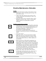
Routine Maintenance Schedule 44
Decontamination 45
Determination of when to Replace HEPA Filters 45
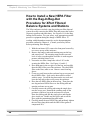
How to Install a New HEPA Filter with Bag-In/Bag-Out
Procedure for XPert Filtered Balance Systems and Stations 46
HEPA Filter Leak Test 47
Setting the Inflow Face Velocity with the Speed Control
Adjustment 49
Calibrate and Operate the Airflow Monitors 50
Guardian Digital 1000 Airflow Monitor 52
Determination of When to Replace Odor Control
Carbon Filters and How to Replace 56
Calculating Odor Control Carbon Filter Life 58
Initial Certification 59
Re-Certification 59
Fluorescent Light Replacement 60
Motorized Impeller Replacement 60
Speed Control Replacement 62
CHAPTER 7 ACCESSORIZING & MODIFYING YOUR
FILTERED ENCLOSURE 63
CHAPTER 8 TROUBLESHOOTING & SERVICER
OPERATING LOG 69
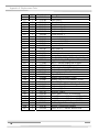
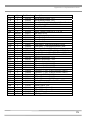
APPENDIX A: FILTERED ENCLOSURE COMPONENTS
AND REPLACEMENT PARTS 73
APPENDIX B: DIMENSIONS AND EXHAUST OPTIONS 79
APPENDIX C: FILTERED ENCLOSURE SPECIFICATIONS 83
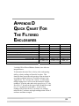
APPENDIX D: QUICK CHART FOR THE FILTERED
ENCLOSURES 89
APPENDIX E: REFERENCES ON VENTILAITON, SAFETY,
OCCUPATIONAL HAZARDS, BIOSAFETY
AND DECONTAMINATION 90
DECLARATION OF CONFORMITY 95

1
C
C
H
H
A
A
P
P
T
T
E
E
R
R
1
1
I
I
N
N
T
T
R
R
O
O
D
D
U
U
C
C
T
T
I
I
O
O
N
N
Congratulations on your purchase of a Labconco XPert™ Filtered
Balance System or XPert™ Filtered Balance Station. Your
enclosure provides personnel protection through superior
containment while conserving energy at OSHA approved
velocities as low as 60 feet per minute. It is the result of
Labconco’s more than 50 years experience in manufacturing fume
hoods and more than 30 years experience in manufacturing filtered
enclosures.
These enclosures will effectively contain toxic or noxious
particulates when properly installed and operated. Each enclosure
uses a single HEPA filter, which is rated at least 99.99% efficient
for 0.3-micron particles. Additionally, an accessory Odor Control
carbon filter may be added to adsorb nuisance odors from organic
vapors, formaldehyde or ammonia and amines. The XPert filtered
enclosures offer many unique features to enhance safety,
performance, and energy savings. To take full advantage of them,
please acquaint yourself with this manual and keep it handy for
future reference. If you are unfamiliar with how high performance
HEPA filtered enclosures operate, please review Chapter 4: High
Performance Features and Safety Precautions before you begin
working in the enclosure. Even if you are an experienced user,
please review Chapter 5: Using Your HEPA Filtered Enclosure,
which describes the XPert features so that you can use the filtered
enclosure efficiently. For weighing hazardous and nuisance
powders, Labconco recommends the purchase of the XPert Filtered
Balance System or XPert Filtered Balance Station. Both XPert

2
Chapter 1: Introduction
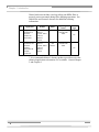
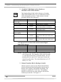
filtered enclosures include a true bag-in/bag-out HEPA filter to
properly protect personnel during filter changing operations. See
chart below and contact Labconco for additional ordering
information.
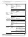
No. Application Product Filters
Bag-in/Bag-out
HEPA
UV
Light
1. Weighing
Hazardous &
Nuisance
Powders &
Particulates
XPert Filtered
Balance
System, XPert
Filtered
Balance
Station
HEPA Required,
included with
XPert
No
2. Weighing
Hazardous and
Nuisance
Powders,
Particulates &
Volatile
Chemicals
XPert Filtered
Balance
System, XPert
Filtered
Balance
Station
HEPA
and
Carbon*
Required,
included with
XPert
No
* It is recommended that a Labconco product specialist review the
chemical application to determine if it is suitable. Consult Chapter
5 and Chapter 6.

3
Chapter 1: Introduction
About This Manual
This manual is designed to help you learn how to install, use, and
maintain your filtered enclosure. Instructions for installing
optional equipment or accessory carbon filters on your filtered
enclosure are also included.
Chapter 1: Introduction provides a brief overview of the filtered
enclosure, explains the organization of the manual, and defines the
typographical conventions used in the manual.
Chapter 2: Prerequisites explains what you need to do to prepare
your site before you install the filtered enclosure. Electrical and
service requirements are discussed.
Chapter 3: Getting Started contains the information you need to
properly unpack, inspect, install, and certify the filtered enclosure.
Chapter 4: High Performance Features and Safety Precautions
explains how the XPert filtered enclosure operates and the
appropriate precautions you should take when using it.
Chapter 5: Using Your Filtered Enclosure discusses the basic
operation of how to prepare, use and shut down your filtered
enclosure.
Chapter 6: Maintaining Your Filtered Enclosure explains how to
perform routine maintenance on the filtered enclosure.
Chapter 7: Accessorizing Your Filtered Enclosure explains
acceptable modifications to the filtered enclosure or how to add
accessories.
Chapter 8: Troubleshooting contains a table of problems you may
encounter while using the filtered enclosure including the probable
causes of the problems and suggested corrective actions.
Appendix A: Components and Replacement Parts contains labeled
diagrams of all of the components of the filtered enclosures.
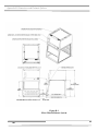
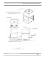
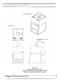
Appendix B: Dimensions and Exhaust Options contains
comprehensive diagrams showing all of the dimensions for the
filtered enclosures.

4
Chapter 1: Introduction
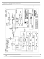
Appendix C: Specifications contains the electrical requirements for
filtered enclosures. Wiring diagrams are also included.
Appendix D: Quick Chart provides an airflow table and test data
for the filtered enclosures.
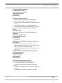
Appendix E: References lists the various resources available that
address laboratory ventilation and biosafety.
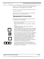
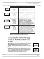
Typographical Conventions
Recognizing the following typographical conventions will help
you understand and use this manual:
• Book, chapter, and section titles are shown in italic type (e.g.,
Chapter 3: Getting Started).
• Steps required to perform a task are presented in a numbered
format.
• Comments located in the margins provide suggestions,
reminders, and references.
• Critical information is presented in boldface type in paragraphs
that are preceded by the exclamation icon. Failure to comply
with the information following an exclamation icon may result
in injury to the user or permanent damage to the enclosure.
• Critical information is presented in boldface type in paragraphs
that are preceded by the wrench icon. A trained certifier or
contractor should only perform these operations. Failure to
comply with the information following a wrench icon may
result in injury to the user or permanent damage to your hood.
• Important information is presented in capitalized type in
paragraphs that are preceded by the pointer icon. It is
imperative that the information contained in these paragraphs
be thoroughly read and understood by the user.
• A number icon precedes information that is specific to a
particular model of enclosure. The 2' icon indicates the text is
specific to the 2-foot wide model. The 3' icon indicates the text
is specific to the 3-foot model, etc.
☞
2'
3' 4'
!

5
C
C
H
H
A
A
P
P
T
T
E
E
R
R
2
2
P
P
R
R
E
E
R
R
E
E
Q
Q
U
U
I
I
S
S
I
I
T
T
E
E
S
S
Before you install the filtered enclosure, you need to prepare your
site for installation. You must be certain that the area is level and
of solid construction. In addition, a dedicated source of electrical
power should be located near the installation site to power the
filtered enclosure, balance and other apparatus. Additionally, the
enclosure should be strategically placed in the lab to provide
efficient workflow.
Carefully read this chapter to learn the requirements for your
installation site:
• The support, vibration and movement requirements.
• The temperature variation requirements.
• The humidity and static electricity requirements.
• The location and air current requirements.
• The exhaust and blower requirements.
• The electrical power requirements.
• The space requirements.
Refer to Appendix B: XPert Dimensions for complete enclosure
dimensions.
Refer to Appendix C: XPert Specifications for complete filtered
enclosure electrical and environmental conditions, specifications
and requirements.

6
Chapter 2: Prerequisites
Support, Vibration and Movement
Requirements
At a minimum, the supporting structure usually consists of a base
cabinet and chemical-resistant work surface.
The ability for analytical balances to accommodate vibration varies
with type and brand. More advanced balances have improved
tolerance, however in the preparation of a balance enclosure site,
please consider the following:
• Avoid tubular stands or mobile benches that have the potential
of moving when touched.
• Work surfaces should be of a thick rigid material that remains
stable when buttons are pressed. An epoxy benchtop or
accessory work surface is a minimum requirement.
• A bench that is rigidly mounted to the floor or fixed to the
wall, but not both, may be appropriate.
• The corners of a building typically have less vibration than the
center.
• The bench with the balance enclosure should not contain any
vibration-producing equipment, such as shakers or pumps.
• Marble, granite or epoxy balance tables are generally
recommended by the manufacturers of analytical and
microbalances. (See the installation instructions in Chapter 3).
• Marble slabs with dampening pads placed within the enclosure
are also an effective low cost means of controlling vibration.
Temperature Variation
Requirements
The extent the balance readings are influenced by temperature
variations is a function of the balance design. Most manufacturers
would suggest that a temperature drift of 1-2°C is generally
tolerable. Only validation through your Operational Qualification
protocol can define what is acceptable. To minimize the potential
for temperature variations:
• Never install balances near heating sources such as radiators
and hot plates.
• Do not place the balance and enclosure on a bench that would
receive direct sunlight.

7
Cha
p
ter 2: Prere
q
uisite
s
Humidity and Static Electricity
Requirements
Electrostatics can be troublesome in a balance enclosure. It is
important to understand and, to the extent possible, control static
charges. An electrostatic charged vessel, sample or enclosure can
apply forces and lead to errors in weighing. The repulsion or
attraction can be detected with micro, semi micro and analytical
balances. Static charges can also lead to particulates being
attracted to surfaces within the balance enclosure. Containment of
harmful powders, prevention of cross-contamination and clean up
are enhanced when static attraction of powders is minimized. The
construction of the XPert Filtered Balance System and XPert
Filtered Balance Station avoid the use of plastics, which are highly
insulative. The advantages to the glass and epoxy-coated metal
construction are twofold:
1. The enclosure does not contribute high electrostatic forces
affecting the precision of the balance.
2. The attraction and ultimate accumulation of powders,
(hazardous or nuisance), are minimized on the inside of the
enclosure.
To correct or ensure against electrostatic issues, the following
additional measures may be prescribed to improve weighing
operations.
• Maintain a humidity level between 45 and 60%. The ability to
sustain this humidity range can be challenging depending
upon the regional climate and HVAC system.
• Ionizers in various forms (guns, bars and blowers) are
effective ways to flood an area with ions and essentially
“neutralize” electrostatic electricity.
Background on Electrostatics or
Static Electricity
Electrostatic charges on a surface such as the wall of a balance
enclosure are not created by moving air. Gases do not cause the
charge. Impurities within the air impinging upon surfaces dictate
the polarity and magnitude of the charge. The process,
triboelectrification, occurs when the dust particles contact the
surface, creating friction and electrons move across the interface.

8
Chapter 2: Prerequisites
The ability of a material to become polarized is a property known
as permittivity. On highly insulative materials like acrylic, ions or
charged molecules are strongly bound to the surface by
polarization forces. The higher the force, the higher is the
permittivity value of the material. It is suggested by balance
manufacturers that the use of high permittivity materials, such as
plastic be avoided.
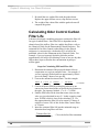
Since static electricity is a surface phenomenon, materials can also
be classified by their surface resistivity measured in ohms per
square. The table below lists the surface resistivity of various
classes of material.
Surface Resistivity Table
Material Surface Resistivity Example
Conductive
0 → 10
5
Ω per square
Skin, Metals
Static dissipative
10
5
→ 10
9
Ω per square
Glass
Antistatic
10
9
→ 10
12
Ω per square
Polyethylene bag
Insulative
10
12
Ω per square→
Acrylic, Packing foam, Styrofoam
Location and Air Current
Requirements
The XPert Filtered Enclosures have been designed to contain
hazards by negating typical cross drafts and turbulence within the
opening. Air movement does not affect most modern balances
with draft shields. However, as a precautionary safety measure
and a higher level of quality management, it is recommended that
the enclosure be placed in an area to avoid:
• High traffic areas where walking might cause an air
disturbance or be a nuisance to balance readings.
• Overhead or wall HVAC diffusers, fans, radiators or other lab
equipment producing air currents.
• Next to doorways or windows that may be opened.
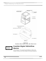
Exhaust and Blower
Requirements
The XPert Filtered Balance System uses an integral motorized
impeller to draw room air past the operator and through the
enclosure. This contaminated air is then pushed through the HEPA
filter. The HEPA-filtered exhaust air is then forced out the top of
the enclosure. An optional carbon filter may be installed on the
downstream side of the HEPA filter to protect against nuisance
odors.
XPert
System

9
Cha
p
ter 2: Prere
q
uisite
s
The HEPA-filtered exhaust air can be recirculated into the
laboratory or exhausted outside with the addition of the exhaust
connection kit and remote blower listed in Chapter 7.
The XPert Filtered Balance Station does not include the motorized
impeller and must be exhausted to the outside by a remote blower.
The XPert Filtered Balance Station remote blower may be
switched from the blower switch on the enclosure. See electrical
Requirements in Chapter 2, and Electrical Supply Connections in
Chapter 3. Only one 6" exhaust connection is required for the 2',
3', or 4' XPert Filtered Balance Stations to exhaust to the outside.
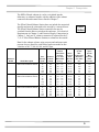
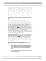
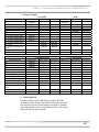
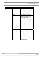
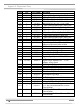
Data for the exhaust volume, noise pressure and enclosure static
pressure loss are listed for each filtered enclosure model at face
velocities of 60, 75, 80, 90, 100, and 105 fpm.
Enclosure
Width Model Description
Face
Velocity
(fpm)
Exhaust
Volume
(CFM)
XPert
Station
Initial Static
Pressure
Loss with
HEPA filter
(in w.g.)
XPert
System
Noise
Pressure
db(A)
Xpert
System
Max.
Equivalent
Resistance
of 6" Duct
(Ft)
Xpert
System
Max.
External
Static
Pressure
2' 2' XPert Filtered Balance System
2' XPert Filtered Balance Station
60
75
80
90
100
105
85
110
115
130
145
155
.35"- .41"
.45" - .54"
.48" - .57"
.56" - .65"
.62" - .72"
.65" - .76"
48-53
49-55
50-56
51-57
53-58
54-59
400
220
200
140
80
70
.20"
.19"
.18"
.16"
.13"
.12"
3' 3' XPert Filtered Balance System
3' XPert Filtered Balance Station
60
75
80
90
100
105
130
165
175
200
220
230
.37" - .43"
.50" - .58"
.53" - .62"
.61" - .71"
.68" - .79"
.71" - .88"
48-53
52-56
53-57
55-58
58-61
60-64
130
65
50
35
25
20
.15"
.12"
.11"
.09"
.08"
.07"
4' 4' XPert Filtered Balance System
4' XPert Filtered Balance Station
60
75
80
90
100
105
175
220
235
265
295
310
.40" - .46"
.53" - .62"
.57" - .66"
.68" - .78"
.76" - .87"
.80" - .91"
49-54
54-58
58-61
60-63
62-66
64-67
100
60
50
35
25
20
.20"
.19"
.18"
.16"
.13"
.12"
XPert
Station

10
Chapter 2: Prerequisites
Proper blower selection can be determined from these exhaust
requirements and the total system static pressure loss. For outside
exhaust, the enclosure must be connected to either a dedicated
blower or a house exhaust system.
Labconco offers accessory remote blowers listed in Chapter 7.
Contact Labconco for blower sizing assistance.
If the enclosure is connected directly to a house exhaust system, an
adjustable damper (or valve) must be installed to control the
airflow properly. This is equally important when a house exhaust
system is controlling multiple filtered enclosures. See Chapter 7
for accessory adjustable damper ordering information.
Electrical Requirements
Standard duplex electrical receptacles should be nearby for
connecting the filtered enclosure, or other equipment, such as a
balance for weighing operations. The enclosures include iris pass-
throughs to allow electrical cords through the back of the enclosure
without leaving a large hole for contaminants to escape.
The remote blower for the XPert Filtered Balance Station may be
connected to the blower switch on the enclosure. The blower
switch is connected to a relay whose wires are terminated in the
junction box behind the front panel. We recommend a maximum
amperage of 6 amps for this circuit to the remote blower. Please
refer to the wiring diagrams in Appendix C. Connect the blower
wires inside the junction box to the remote blower per local
electrical codes.
Space Requirements
The dimensions for the different models are shown in Appendix B:
Dimensions.
!
XPert
Station

11
C
C
H
H
A
A
P
P
T
T
E
E
R
R
3
3
G
G
E
E
T
T
T
T
I
I
N
N
G
G
S
S
T
T
A
A
R
R
T
T
E
E
D
D
Now that the site for your filtered enclosure is properly prepared,
you are ready to unpack, inspect, install, and validate your system.
Read this chapter to learn how to:
• Unpack and move the enclosure.
• Set up the enclosure with the proper supporting structure
and work surface.
• Connect to an exhaust system if applicable.
• Installation of HEPA and accessory Odor Control carbon
filters.
• Connect the electrical supply.
• Set the face velocity with the speed control adjustment.
• Arrange validation for the enclosure.
• Seal the enclosure to the work surface.
Depending upon which model you are installing, you may need
common mechanical and electrical installation tools in addition to
5/16", 3/8", 7/16", and 1/2" wrenches, ratchets, sockets, a nut
driver set, a flat-blade screwdriver, a Phillips screwdriver, and a
carpenter level to complete the instructions in the chapter.
Each enclosure model weighs between 125 to 195
lbs. each (55 to 85 kg). The shipping container
allows for lifting with a mechanical lift truck or
floor jack. If you must lift the enclosure
manually, follow safe-lifting guidelines. Do not
lift by the front air foil.
!

12
Chapter 3: Getting Started
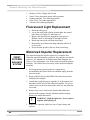
Unpacking the Enclosure
Carefully remove the shrink-wrap or carton on the enclosure and
inspect it for damage that may have occurred in transit. If
damaged, notify the delivery carrier immediately and retain the
entire shipment intact for inspection by the carrier.
DO NOT RETURN GOODS WITHOUT THE
PRIOR AUTHORIZATION OF LABCONCO.
UNAUTHORIZED RETURNS WILL NOT BE
ACCEPTED.
IF ENCLOSURE WAS DAMAGED IN TRANSIT,
YOU MUST FILE A CLAIM DIRECTLY WITH
THE FREIGHT CARRIER. LABCONCO
CORPORATION AND ITS DEALERS ARE NOT
RESPONSIBLE FOR SHIPPING DAMAGES.
Do not discard the packing material until you have checked all of
the components and tested the enclosure.
We recommend that you do not remove the enclosure from its
shipping container until it is ready to be placed into its final
location. Move the unit by placing a flat, low dolly under the
shipping skid, or by using a floor jack.
Do not move the enclosure by tilting it onto a
hand truck.
Installing the Filtered Enclosure
on a Supporting Structure and
Work Surface
Use caution when lifting or moving the enclosure.
When installing the enclosure onto a chemical-resistant work
surface or benchtop, ensure that the structure can safely support the
combined weight of the enclosure and any related equipment. The
work surface should be at least as wide as the enclosure to properly
support it. The front of the enclosure should be aligned within
The United States
I
nterstate Commerce
Commission rules
require that claims be
f
iled with the delivery
carrier within fifteen (15)
days of delivery.
!
☞
☞

13
Cha
p
ter 3: Gettin
g
Starte
d
0.36" of the front of the work surface. Mounting holes are
provided in the Labconco accessory work surfaces to secure the
enclosure.
Work Surface Specifications
The work surface should be smooth, rigid, and durable, such as a
chemical-resistant epoxy resin. The surface should be non-porous
and resistant to the powders, solvents and chemicals used in
conjunction with the XPert Filtered Enclosure. The work surface
should also contain a dished recessed area for containing primary
spills.
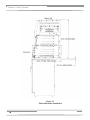
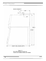
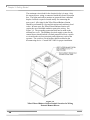
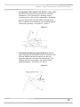
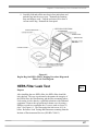
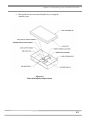
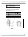
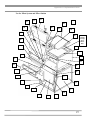
Work Surface and HEPA Filtered Enclosure Installation
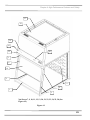
1. Level the base cabinets and the work surface. Work
surface should be placed flush with the front of the base
cabinet as shown in Figure 3-1.
2. Position the work surface in its intended location and with
the front of the work surface towards you. (Rear mounting
holes are located close to the rear edge.)
3. Secure the work surface to the base cabinet with a
structural adhesive or silicone sealant.
4. Insert the supplied mounting screws in the four holes.
Allow a minimum of 1/8" clearance under the head of the
screw for positioning the enclosure.
5. Place the enclosure on the work surface and slide the rear
flange and front air foil flanges under the mounting screw
heads.
6. Tighten the four screws to complete the installation.

14
Chapter 3: Getting Started
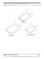
Figure 3-1
Filtered Enclosure Installation

15
Cha
p
ter 3: Gettin
g
Starte
d
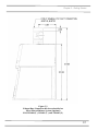
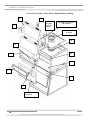
Connecting to the
Exhaust System (Optional
on XPert Filtered Balance
System)
The exhaust system should be installed by a
qualified HVAC contractor.
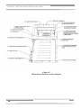
The exhaust connection on the XPert Filtered
Balance Station has been designed to accept 6"
diameter ductwork as shown in Figure 3-2. The
exhaust connection ships uninstalled on the top and
needs to be fastened with the screws provided. See
Chapter 7 for ordering exhaust transition kits for the
XPert Filtered Balance System. Exhaust transition
kits aid in the removal of chemicals or applications
where a higher degree of powder and particulate
removal is required. Review Chapter 2 for exhaust
prerequisites and review Chapter 7 for ordering
blower exhaust equipment. See Figure 3-2 for the
XPert Station and Figure 3-3 for exhaust kit options
for the XPert Filtered Balance System.
Consult Labconco Customer Service should you
require help sizing your blower for the exhaust
volume and system static pressure loss.
To ensure compatibility, the selected exhaust duct
material should match the enclosure, procedures
and chemical applications.
!
WARNING: The weight of the exhaust
ductwork system must be supported
independently of the enclosure superstructure
or damage may occur.
!
XPert
Station
Page is loading ...
Page is loading ...
Page is loading ...
Page is loading ...
Page is loading ...
Page is loading ...
Page is loading ...
Page is loading ...
Page is loading ...
Page is loading ...
Page is loading ...
Page is loading ...
Page is loading ...
Page is loading ...
Page is loading ...
Page is loading ...
Page is loading ...
Page is loading ...
Page is loading ...
Page is loading ...
Page is loading ...
Page is loading ...
Page is loading ...
Page is loading ...
Page is loading ...
Page is loading ...
Page is loading ...
Page is loading ...
Page is loading ...
Page is loading ...
Page is loading ...
Page is loading ...
Page is loading ...
Page is loading ...
Page is loading ...
Page is loading ...
Page is loading ...
Page is loading ...
Page is loading ...
Page is loading ...
Page is loading ...
Page is loading ...
Page is loading ...
Page is loading ...
Page is loading ...
Page is loading ...
Page is loading ...
Page is loading ...
Page is loading ...
Page is loading ...
Page is loading ...
Page is loading ...
Page is loading ...
Page is loading ...
Page is loading ...
Page is loading ...
Page is loading ...
Page is loading ...
Page is loading ...
Page is loading ...
Page is loading ...
Page is loading ...
Page is loading ...
Page is loading ...
Page is loading ...
Page is loading ...
Page is loading ...
Page is loading ...
Page is loading ...
Page is loading ...
Page is loading ...
Page is loading ...
Page is loading ...
Page is loading ...
Page is loading ...
Page is loading ...
Page is loading ...
Page is loading ...
Page is loading ...
Page is loading ...
Page is loading ...
-
 1
1
-
 2
2
-
 3
3
-
 4
4
-
 5
5
-
 6
6
-
 7
7
-
 8
8
-
 9
9
-
 10
10
-
 11
11
-
 12
12
-
 13
13
-
 14
14
-
 15
15
-
 16
16
-
 17
17
-
 18
18
-
 19
19
-
 20
20
-
 21
21
-
 22
22
-
 23
23
-
 24
24
-
 25
25
-
 26
26
-
 27
27
-
 28
28
-
 29
29
-
 30
30
-
 31
31
-
 32
32
-
 33
33
-
 34
34
-
 35
35
-
 36
36
-
 37
37
-
 38
38
-
 39
39
-
 40
40
-
 41
41
-
 42
42
-
 43
43
-
 44
44
-
 45
45
-
 46
46
-
 47
47
-
 48
48
-
 49
49
-
 50
50
-
 51
51
-
 52
52
-
 53
53
-
 54
54
-
 55
55
-
 56
56
-
 57
57
-
 58
58
-
 59
59
-
 60
60
-
 61
61
-
 62
62
-
 63
63
-
 64
64
-
 65
65
-
 66
66
-
 67
67
-
 68
68
-
 69
69
-
 70
70
-
 71
71
-
 72
72
-
 73
73
-
 74
74
-
 75
75
-
 76
76
-
 77
77
-
 78
78
-
 79
79
-
 80
80
-
 81
81
-
 82
82
-
 83
83
-
 84
84
-
 85
85
-
 86
86
-
 87
87
-
 88
88
-
 89
89
-
 90
90
-
 91
91
-
 92
92
-
 93
93
-
 94
94
-
 95
95
-
 96
96
-
 97
97
-
 98
98
-
 99
99
-
 100
100
-
 101
101