
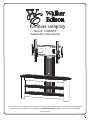
Item #: V42MWF
Assembly Instructions
For our most current instructions, to request missing, lost or broken parts, or for any other Customer
Service issues, please visit our website at www.walkeredison.com or call us at 877-207-5906.
Revised 11/2011

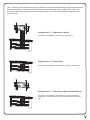
This TV stand can be assembled in three (3) different configurations depending on personal preference.
Each configuration is outlined below with the appropriate assembly steps required. Also, each step
throughout these assembly instructions includes a small icon of the corresponding configuration for
your reference.
Configuration 1 - TV Mounted on Stand
To build this configuration, follow steps 1 through 12.
Configuration 2 - TV Stand Only
To build this configuration, follow steps 1 through 5 and step 11.
Configuration 3 - TV Mounted to Wall with Stand Below
To build this configuration, follow steps 1 through 5 and step 9.
Follow step 13 for instructions on how to attach the mount to the
wall.

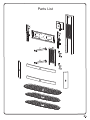
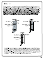
Parts List

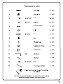
Hardware List
Bolt
Suction cup pin
Bolt
Flange bolt
Bolt

Bolt
Bolt
Bolt
Bolt
Bolt
Bolt
Bolt
Bolt
Bolt
Bolt
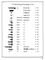
TV Mounting Hardware List

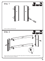
Screw cam bolts (1) into legs (A,B).
Insert cam locks (2) into front panels (C,D). Attach legs (A,B) to front panels (C,D) using cam bolts as guides.
Tighten cam locks (2) with a screwdriver.

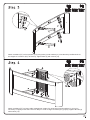
Attach crossbars (E,F) to front panels (C,D) using bolts (3) and washers (4). Note that the predrilled holes on
the lengths of crossbars (E,F) will face up. Tighten bolts (3) with wrench (12).
Attach crossbars (E,F) to lower cable management system (G) using bolts (3) and washers (4). It may be
necessary to slightly loosen the bolts from Step 3 in order to align crossbars (E,F) properly. Tighten all bolts (3)
with wrench (12).

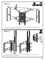
Screw suction cup pins (5) into crossbars (E,F). Screw pins (6) into legs (A,B) and lower cable management
system (G). Insert rubber pads (9) into legs (A,B).
Attach upper cable management system (H) to lower cable management system (G) using bolts (7) and
washers (4). Tighten bolts (7) with wrench (12).
E
E
F
B
A
G
F

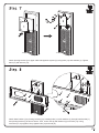
Attach pivoting bracket (I) to upper cable management system (H) using bolts (14) and washers (4). Tighten
bolts (14) with wrench (12).
Attach base bracket (J) to pivoting bracket (I) by inserting bolts (14) with washers (4) through base bracket (J)
and pivoting bracket (I) as shown above. Then, screw nuts (8) with washers (4) onto bolts (14). Using
wrenches (12,13) together, firmly tighten bolts (14) and nuts (8).

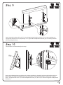
Attach mounting brackets (K) to the TV using the appropriate hardware from the TV mounting hardware kit.
Appropriate hardware will vary depending on TV type. Attach tilt adjustment knobs (10) to mounting brackets
(K) using flange bolts (11).
Loosen the adjustment knobs at the base of mounting brackets (K). Carefully hook mounting brackets (K) onto
base bracket (J). Tighten the adjustment knobs at the base of mounting brackets (K) to secure the TV to the
mount. To adjust the tilt of the TV, loosen tilt adjustment knobs (10), tilt TV up or down then tighten tilt adjustment
knobs (10).
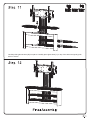
Two people are recommended for this step!

Carefully slide glass shelves (M) into place. Carefully place glass shelf (L) on top of the stand and gently push
down to secure.

-
 1
1
-
 2
2
-
 3
3
-
 4
4
-
 5
5
-
 6
6
-
 7
7
-
 8
8
-
 9
9
-
 10
10
-
 11
11
-
 12
12


Walker CMWF42-1 User manual
- Type
- User manual
- This manual is also suitable for
Ask a question and I''ll find the answer in the document
Finding information in a document is now easier with AI
Related papers
Other documents
-
Pro-Form CROSSWALK si User manual
-
ProForm PFTL313340 User manual
-
-
Weider PLATINUM 600 SYSTEM WESY6863 User manual
-
-
Weider 831.153990 User manual
-
-
HealthRider HRSY2308 230 GYM SYSTEM User manual
-
-
NordicTrack Futura 2200 User manual