
ITALIANO
ESPAÑOL
FRANÇAIS
DEUTSCH
ΕΛΛΗΝΙΚΆ
ČEŠTINA
NEDERLANDS
POLSKI
LIMBA ROMÂNĂ
ENGLISH
INSTALLATION MANUAL
AIR
CONDITIONER
www.lg.com
Floor Standing(Console)
Original instruction
Please read this installation manual completely before installing the product.
Installation work must be performed in accordance with the national wiring
standards by authorized personnel only.
Please retain this installation manual for future reference after reading it thoroughly.
Ɠ This product contains Fluorinated Greenhouse Gases. (R410A)
[
Representative
] LG Electronics Inc. EU Representative : LG Electronics European Shared
Service Center B.V. Krijgsman 1, 1186 DM Amstelveen, The Netherlands
[Manufacturer] LG Electronics Inc. Changwon 2nd factory 84, Wanam-ro, Seongsan-gu,
Changwon-si, Gyeongsangnam-do, KOREA
P/NO : MFL67855505

2 Air Conditioner
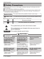
Safety Precautions
To prevent the injury of the user or other people and property damage, the following instructions
must be followed.
n Be sure to read before installing the air conditioner.
n Be sure to observe the cautions specified here as they include important items related to safety.
n Incorrect operation due to ignoring instruction will cause harm or damage. The seriousness is
classified by the following indications.
n The meanings of the symbols used in this manual are as shown below.
WARNING
CAUTION
This symbol indicates the possibility of death or serious injury.
This symbol indicates the possibility of injury or damage to properties only.
WARNING
Be sure not to do.
Be sure to follow the instruction.
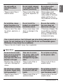
Safety Precautions
n Installation
Do not use a defective
or underrated circuit
breaker. Use this
appliance on a dedi-
cated circuit.
• There is risk of fire or
electric shock.
For electrical work, con-
tact the dealer, seller, a
qualified electrician, or
an Authorized Service
Center.
•
Do not disassemble or
repair the product. There is
risk of fire or electric shock.
Always ground the
product.
• There is risk of fire or
electric shock.
Install the panel and
the cover of control
box securely.
• There is risk of fire or
electric shock.
Always install a dedi-
cated circuit and break-
er.
• Improper wiring or instal-
lation may cause fire or
electric shock
Use the correctly rated
breaker or fuse.
• There is risk of fire or
electric shock.
This symbol alerts you to the risk of electric shock.
This symbol alerts you to hazards that may cause harm to
the air conditioner.
This symbol indicates special notes.
NOTICE

Installation Manual 3
ENGLISH
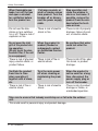
Safety Precautions
n Operation
Do not let the air condi-
tioner run for a long time
when the humidity is
very high and a door or a
window is left open.
• Moisture may condense
and wet or damage fur-
niture.
Take care to ensure
that power cable could
not be pulled out or
damaged during oper-
ation.
• There is risk of fire or
electric shock.
Do not place anything
on the power cable.
• There is risk of fire or
electric shock.
Do not plug or unplug
the power supply plug
during operation.
• There is risk of fire or
electric shock.
Do not touch(operate)
the product with wet
hands.
• There is risk of fire or
electrical shock.
Do not place a heater
or other appliances
near the power cable.
• There is risk of fire and
electric shock.
Use a vacuum pump or Inert (nitrogen) gas when doing leakage test or air
purge. Do not compress air or Oxygen and Do not use Flammable gases.
Otherwise, it may cause fire or explosion.
• There is the risk of death, injury, fire or explosion.
Do not modify or
extend the power
cable.
• There is risk of fire or
electric shock.
Do not install, remove,
or re-install the unit by
yourself (customer).
• There is risk of fire, elec-
tric shock, explosion, or
injury.
Be cautious when
unpacking and
installing the product.
• Sharp edges could
cause injury. Be espe-
cially careful of the case
edges and the fins on
the condenser and evap-
orator.
For installation, always
contact the dealer or an
Authorized Service Center.
• There is risk of fire, elec-
tric shock, explosion, or
injury.
Do not install the
product on a defective
installation stand.
• It may cause injury, acci-
dent, or damage to the
product.
Be sure the installa-
tion area does not
deteriorate with age.
• If the base collapses, the
air conditioner could fall
with it, causing property
damage, product failure,
and personal injury.

4 Air Conditioner
Safety Precautions
When flammable gas
leaks, turn off the gas
and open a window
for ventilation before
turn the product on.
• Do not use the tele-
phone or turn switches
on or off. There is risk of
explosion or fire
If strange sounds, or
small or smoke comes
from product. Turn the
breaker off or discon-
nect the power supply
cable.
• There is risk of electric
shock or fire.
Stop operation and
close the window in
storm or hurricane. If
possible, remove the
product from the win-
dow before the hurri-
cane arrives.
• There is risk of property
damage, failure of prod-
uct, or electric shock.
Do not open the inlet
grill of the product dur-
ing operation.
(Do not touch the elec-
trostatic filter, if the unit
is so
equipped.)
• There is risk of physical
injury, electric shock, or
product failure.
When the product is
soaked (flooded or
submerged), contact
an Authorized Service
Center.
• There is risk of fire or
electric shock.
Be cautious that water
could not enter the
product.
• There is risk of fire, elec-
tric shock, or product
damage.
Ventilate the product
from time to time
when operating it
together with a stove,
etc.
• There is risk of fire or
electric shock.
Turn the main power
off when cleaning or
maintaining the prod-
uct.
• There is risk of electric
shock.
When the product is
not be used for a long
time, disconnect the
power supply plug or
turn off the breaker.
• There is risk of product
damage or failure, or
unintended operation.
Take care to ensure that nobody could step on or fall onto the outdoor
unit.
• This could result in personal injury and product damage.

Safety Precautions
Installation Manual 5
ENGLISH
n Installation
Always check for gas
(refrigerant) leakage
after installation or
repair of product.
• Low refrigerant levels
may cause failure of
product.
Install the drain hose
to ensure that water is
drained away properly.
• A bad connection may
cause water leakage.
Keep level even when
installing the product.
• To avoid vibration or
water leakage.
Do not install the prod-
uct where the noise or
hot air from the outdoor
unit could damage the
neighborhoods.
• It may cause a problem
for your neighbors.
Use two or more peo-
ple to lift and trans-
port the product.
• Avoid personal injury.
Do not install the
product where it will
be exposed to sea
wind (salt spray)
directly.
• It may cause corrosion
on the product.
Corrosion, particularly on
the condenser and evap-
orator fins, could cause
product malfunction or
inefficient operation.
Do not expose the skin
directly to cool air for
long periods of time.
(Don't sit in the draft.)
• This could harm to your
health.
Do not use the product
for special purposes,
such as preserving
foods, works of art, etc.
It is a consumer air con-
ditioner, not a precision
refrigeration system.
• There is risk of damage
or loss of property.
Do not block the inlet
or outlet of air flow.
• It may cause product
failure.
n Operation
CAUTION

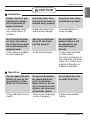
6 Air Conditioner
Safety Precautions
Always insert the filter
securely. Clean the fil-
ter every two weeks or
more often if neces-
sary.
• A dirty filter reduces the
efficiency of the air con-
ditioner and could cause
product malfunction or
damage.
Do not insert hands or
other objects through
the air inlet or outlet
while the product is
operated.
• There are sharp and
moving parts that could
cause personal injury.
Do not drink the water
drained from the prod-
uct.
• It is not sanitary and
could cause serious
health issues.
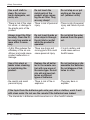
Use a firm stool or
ladder when cleaning
or maintaining the
product.
• Be careful and avoid
personal injury.
Replace the all batter-
ies in the remote con-
trol with new ones of
the same type. Do not
mix old and new bat-
teries or different
types of batteries.
• There is risk of fire or
explosion
Do not recharge or dis-
assemble the batteries.
Do not dispose of bat-
teries in a fire.
• They may burn or
explode.
If the liquid from the batteries gets onto your skin or clothes, wash it well
with clean water. Do not use the remote if the batteries have leaked.
• The chemicals in batteries could cause burns or other health hazards.
Use a soft cloth to
clean. Do not use
harsh detergents, sol-
vents, etc.
• There is risk of fire, elec-
tric shock, or damage to
the plastic parts of the
product.
Do not touch the
metal parts of the
product when remov-
ing the air filter. They
are very sharp!
• There is risk of personal
injury.
Do not step on or put
anyting on the prod-
uct. (outdoor units)
• There is risk of personal
injury and failure of prod-
uct.

Connecting cable
(Optional Parts)
Vinyl tape (Wide)
• Apply after carrying out a
drainage test.
• To carry out the drainage
test, remove the air filters
and pour water into the heat
exchanger.
Saddle
(3)
(6)
(5)
(7)
(2)
Gas side piping (Optional Parts)
Liquid side piping (Optional Parts)
Additional drain pipe
Vinyl tape (Narrow)
Drain Hose(1)
Sleeve
Bushing-Sleeve
Putty(Gum Type Sealant)
Bend the pipe as closely
on the wall as possible,
but be careful that it
doesn't break.
You should purchase the installation parts.
NOTICE
Installation Manual 7
Installation
ENGLISH
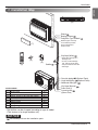
1. Installation Map
※(4),(8),(9) ’ Screw
- The feature can be changed according to type of model.
(This feature is for single outdoor unit)
ACCESSORIES
(1) Drain Hose 1EA
(2) Remote Controller 1EA
(3) Remote Controller Holder 1EA
(4) Fixing Screw for R.Controller Holder 2EA
(5) Battery (AAA) 2EA
(6) Install plate 1EA
(7) Allergy Filter 1EA
(8) Fixing Screw for Install Plate 4*25mm 5EA
(9) Wood Screw for Indoor fixation 6EA

8 Air Conditioner
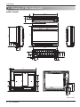
584
125
90
600
160
80
37
100
639
700
666
210
95
45
80
18
82.5
68.5
150
37
140
120
260.5
220
103
51
87
180
647
26.5
140
140170
170
Installation
2. Drawing of the indoor unit
AQNH**GALAD
(Unit : mm)

Installation Manual 9
ENGLISH
Installation
1.There should not be any heat or steam near the unit.
2. Select a place where there are no obstacles around of the unit.
3. Make sure that condensation drainage can be conveniently routed away.
4. Do not install near a doorway.
5. Ensure that the interval between a wall and the left (or right) of the unit is more than 300mm.
6. Use a metal detector to locate studs to prevent unnecessary damage to the wall.
7. Keep away from electronic ignition type fluorescent lamps as they may shorten the remote con-
troller range.
8.
Please check at least 1m away from television or radio.(It cause interference with the picture or
sound.)
3. Choosing an installation Site
More than 300
250 or below
from the Floor
More than
300
More than
300
(Unit : mm)
• Before choosing the installation site, please obtain user approval
•
If the unit is installed below a window,check the interference of window curtain.(more than 300mm)
NOTICE

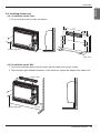
4. Indoor unit installation
10 Air Conditioner
Installation
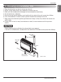
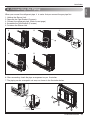
4-1.Preparation / Removing front panel
1. Open the front grille by pulling forward
2. Then pull out the link of grille from groove in front panel.
3. Then pull out 2 hinges of grille from grooves in front panel.
4. Then remove 4 screws, dismount the front panel while pulling it forward.
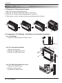
4-2. Preparation / For Moldings , Side Piping, and Concealed Installation
4-2-1 For Moldings
1. Remove the slit portions on the Rear Panel.
4-2-2 For Concealed Installation
1. Remove the 6 screws.
2. Remove the Upper Deco cover.
3. Remove the Side Deco covers.
4-2-3 For Side Piping (Reference 4-2-2.)
1. Remove the Deco Covers.
2. Remove the slit portions
3. Assemble the Deco Covers.
Upper Deco cover
Side Deco cover
Remove

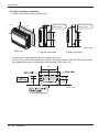
Installation
Installation Manual 11
1. The location of hole is different depending on which side of the pipe is taken out.
2. Drill a hole (Ø70mm)in the point indicated by symbol in the illustration as below
(Unit : mm)
45
90 75
Left bottom piping
Right bottom piping
Left/right piping
Right back piping
60
40
50
Wall
45
90
75
Left back piping
Right back piping
45
ENGLISH
4-3.Refrigerant Piping
- The suggested shortest pipe length is 5m,in order to avoid noise from the outdoor unit and vibra-
tion.
NOTICE

12 Air Conditioner
Installation
• Drill the piping hole with a ø70mm hole core
drill. Drill the piping hole at either the right or
the left with the hole slightly slanted to the
outdoor side.
1. The Outer diameter of Drain
Hose (which is supplied with
indoor unit) is 17mm at connect-
ing end,600mm long.
2. Use commercial rigid PVC pipe
for extension.
3. Insulate the indoor drain pipe
with 10mm or more of insulation
material to prevent condensa-
tion.
5-7mm
(3/16"~5/16")
Indoor
WALL
Outdoor
600
Ø17
[Unit : mm]
103
87
4-4.Drill a Hole in the wall
4-5.Drain piping
- The drain pipe should be inclined downward so that water will flow smoothly without any accu-
mulation.
NOTICE
Do not raise
Accumulated
drain water
Tip of drain hose
dipped in water
Air
Waving
Water
leakage
Water
leakage
Ditch
Less than
50mm gap
Water
leakage

Installation Manual 13
ENGLISH
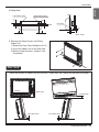
Installation
4-6. Installing Indoor unit
4-6-1 Installation on the Floor.
1. Fix up using 6 screws for floor installation.
4-6-2 Installation on the Wall
1. Fix up the installation plate using 5 screws and the indoor unit using 4 screws.
2.
The installation plate should be fixed on a wall which can support the weight of the indoor unit.
6 screw (M*25L)
64
159
(700)
(Unit : mm)
26
647
180
140
(600)
574
170
170
210
30.5
30.5
140
160
Installation Plate
Molding
4 screw (M*25L)

14 Air Conditioner
Installation
4-6-3 Half concealed installation.
1. Make a wall hole of the size shown Fig-1.
2. Installation of supplemental plate for attaching main unit
• The rear of the unit can be fixed with screws at the points shown in the Fig-2.Be sure to install
the supplemental plate in accordance with the depth of the inner wall.
670
45
585
200
150
Wall
Hole
Supplemental plate
(Field supply)
200
150
95
Supplemental plate
(Field supply)
647
170
140
170
140
(Unit : mm)
1) Normal concealed 2) Deep concealed
(Unit : mm)
<Fig - 1>

Installation Manual 15
ENGLISH
Installation
3.Piping Hole
4. Remove the Deco Covers and Fixing
Indoor Unit
1)
Remove the Deco Covers.(Reference 4-2-2.)
2) Insert the Indoor Unit to the Wall hole.
3) Secure using 6 screws. (shown in the
illustration)
- Check the horizon of Indoor unit with the wall. Please use the Leveler on the drain pan guide.
Wall
Wall
75
50
35
75
Left bottom pipng
Left pipng
45
50
(Unit : mm)
Right bottom pipng
NOTICE
Leveler
Drain pan
Less than 5mm
Less than 5mm Less than 5mm

16 Air Conditioner
Installation
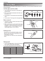
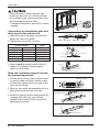
5. Flaring Work
Main cause for gas leakage is due to defect of flaring work. Carry out correct flaring work in the fol-
lowing procedure.
Cut the pipes and the cable.
1. Use the piping kit accessory or the pipes pur-
chased locally.
2. Measure the distance between the indoor and
the outdoor unit.
3. Cut the pipes a little longer than measured dis-
tance.
4. Cut the cable 1.5m longer than the pipe length.
Burrs removal
1. Completely remove all burrs from the cut cross
section of pipe/tube.
2. While removing burrs put the end of the copper
tube/pipe in a downward direction while remov-
ing burrs location is also changed in order to
avoid dropping burrs into the tubing.
Putting nut on
• Remove flare nuts attached to indoor and out-
door unit, then put them on pipe/tube having
completed burr removal.
(not possible to put them on after finishing flare
work)
Flaring work
1. Firmly hold copper pipe in a bar with the dimen-
sion shown in below table table below.
2. Carry out flaring work with the flaring tool.
Copper
pipe
90
Slanted Uneven Rough
Pipe
Reamer
Point down
Flare nut
Copper tube
mm inch mm
Ø6.35 1/4 1.1~1.3
Ø9.52 3/8 1.5~1.7
Ø12.7 1/2 1.6~1.8
Ø15.88 5/8 1.6~1.8
Ø19.05 3/4 1.9~2.1
Outside diameter A
Bar
Copper pipe
Clamp handle
Red arrow mark
Cone
Yoke
Handle
Bar
"A"

Installation Manual 17
ENGLISH
Installation
When you connect the refrigerant pipe, it is easier that you connect the gas pipe first.
1. Hold up the Sensor Link.
2. Separate the Pipe Bracket (2 screws)
3. Connect the refrigerant pipe. (Refer to next page)
4. Assemble the Pipe Bracket (2 screws)
5. Put down the Sensor Link
6. After connecting, check the pipe arrangement as per illustration.
7. The piping can be arranged in six ways as shown in the illustration below.
6. Connecting the Piping
3
1
2
6
5
4
Pipe Guide
Pipe Guide
Connecting Pipe must be placed inner
than the pipe guide.
Connecting
Connecting
Pipe
Pipe
Connecting
Pipe
12
45
3

18 Air Conditioner
Installation
Connecting the installation pipe and
drain hose to the indoor unit.
1. Align the center of the pipes and sufficiently
tighten the flare nut by hand.
2. Tighten the flare nut with a wrench
3. When needed to extend the drain hose of
indoor unit, assembly the drain pipe as
shown on the drawing
Wrap the insulation material around
the connecting portion.
1. Overlap the connection pipe insulation mater-
ial and the indoor unit pipe insulation materi-
al. Bind them together with vinyl tape so that
there may be no gap.
2. Wrap the area which accommodates the rear
piping housing section with vinyl tape.
3. Bundle the piping and drain hose together by
wrapping them with vinyl tape sufficient
enough to cover where they fit into the rear
piping housing section.
If the drain hose is routed inside the room
insulate the hose with an insulation material*
so that dripping from sweating (condensation)
will not damage furniture or floors.
* Foamed polyethylene or equivalent is recom-
mended.
mm inch kgf
.
m
Ø6.35 1/4 1.8~2.5
Ø9.52 3/8 3.4~4.2
Ø12.7 1/2 5.5~6.5
Ø15.88 5/8 6.3~8.2
Ø19.05 3/4 9.9~12.1
Outside diameter Torque
Insulation material
Vinyl tape(narrow)
Connection pipe
Connecting cable
Vinyl tape (wide)
Wrap with vinyl tape
Indoor unit pipe
Pipe
Wrap with vinyl tape
Drain hose
Pipe
Vinyl tape(wide)
Indoor unit tubing Flare nut Pipes
Wrench
Indoor unit tubing
Open-end wrench (fixed)
Connection pipe
Flare nut
Vinyl tape(narrow)
Adhesive
Drain pipe
Indoor unit drain hose
Connecting pipe
Connecting
cable
Tape
Drain hose

Installation Manual 19
ENGLISH
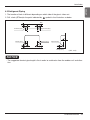
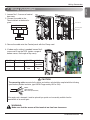
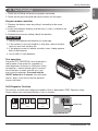
Wiring Connection
1. Loosen No 1,2 screws of control
box cover.
2. Connect the cable to the
Terminal block as below dia-
gram
3. Secure the cable onto the Control panel with the Clamp cord.
4. If indoor unit's setting is needed, loosen No.3
screw and lift up the PCB. (option: usage of
bottom vanes, limit angle of top vane)
If the supply cord is damaged, it must be replaced by a special cord or assembly available from the
manufacturer of its service agent.
The connecting cable connected to the indoor and outdoor unit should be complied with the following
specifications (Rubber insulation, type H05RN-F approved by HAR or SAA).
CAUTION
20mm
GN/YL
NORMAL
CROSS-SECTIONAL
AREA 0.75mm
2
(9k12k/18k Btu/h)
1(L) 2(N) 3
Terminal Block of Indoor Unit
Outdoor
WARNING:
Make sure that the screws of the terminal are free from looseness.
1
1
3
3
2
2
Terminal Block
Connecting Cable
Clamp Cord
Dip S/W Description S/W OFF S/W ON
S/W 5 Install scene Exposed Half
Concealed
S/W 7 Vane Top+Bottom Top vane
vane only
7. Wiring Connection

20 Air Conditioner
Wiring Connection
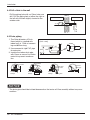
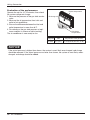
8. Electrical Wiring
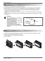
9. Installation of Front Panel
1. All wiring must comply with LOCAL REGULATIONS.
2. Select a power source that is capable of supplying the current required by the air conditioner.
3. Feed the power source to the unit via a distribution switch board designed for this purpose.
4. The terminal screws inside the control box may be loose due to vibration during transport.
Check the screws for loose connection.
(Running the air conditioner with loose connection can overload and damage electrical compo-
nents.)
5. Always ground the air conditioner with a grounding wire and connector to meet the LOCAL REG-
ULATION.
CAUTION:
• The circuit diagram is not subject to
change without notice.
• Be sure to connect wires according
to the wiring diagram.
• Connect the wires firmly, so that not
to be pulled out easily.
• Connect the wires according to
color codes by referring the wiring
diagram.
Air
Conditioner
Main power source
Circuit Breaker
1. Fit the Front Panel onto the indoor unit and push the upper area that are marked with arrows
2. Check the air sensor and install the 4 screws
3. Then assemble the front grille and put the hinges
4. Close the grille.
Page is loading ...
Page is loading ...
Page is loading ...
-
 1
1
-
 2
2
-
 3
3
-
 4
4
-
 5
5
-
 6
6
-
 7
7
-
 8
8
-
 9
9
-
 10
10
-
 11
11
-
 12
12
-
 13
13
-
 14
14
-
 15
15
-
 16
16
-
 17
17
-
 18
18
-
 19
19
-
 20
20
-
 21
21
-
 22
22
-
 23
23


LG Multi-consoles Installation guide
- Type
- Installation guide
Ask a question and I''ll find the answer in the document
Finding information in a document is now easier with AI
Related papers
-
LG AMNC18G2CL0 Owner's manual
-
LG MA09AH1-M User manual
-
LG ARNU15GQAA2.ENWALEU User manual
-
LG ARNU15GQAA4.ENWBLEU Installation guide
-
-
-
LG LS122CE User manual
-
-
LG UM30F User manual
-