Page is loading ...

OPERATIONS
MAINTENANCE
MANUAL
FOOD HOLDING & TRANSPORT CABINETS
WITTCO MODEL NUMBERS
1220-105-2-BC
1220-105-3-BC
1220-105-4-BC

LIMITED WARRANTY
Wittco warrants the Products that it manufactures to be free from defects in materials and workmanship, under normal use and
service, for the periods indicated below from the date of purchase when installed and maintained in accordance with Wittco's
written instructions. Buyer must establish the "Products" purchase date by returning Wittco's Warranty registration Card or by
other means satisfactory to Wittco in its sole discretion.
Wittco warrants its Products to be free from defects in materials and workmanship from the date of purchase (subject to the
foregoing conditions) for the period(s) of time and on the conditions listed below:
a) Ninety (90) days Labor Warranty
b) One (1) Year Parts Warranty
THE FOREGOING WARRANTIES ARE EXCLUSIVE AND IN LIEU OF ANY OTHER WARRANTY, EXPRESSED OR
IMPLIED, INCLUDING BUT NOT LIMITED TO ANY IMPLIED WARRANTY OF MERCHANTABILITY OR FITNESS FOR A
PARTICULAR PURPOSE OR PATENT OR OTHER INTELLECTUAL PROPERTY RIGHT INFRINGEMENT. Without limiting
the generality of the foregoing, SUCH WARRANTIES DO NOT COVER: Coated incandescent light bulbs or heat lamps, all
glass components. Product misuse, tampering, misapplication, application of improper voltage, or recalibration of thermostats or
high limit switches.
LIMITATION OF REMEDIES & DAMAGES
Wittco's liability and Buyer's exclusive remedy hereunder will be limited solely, at Wittco's option, to repair or replacement by a
Wittco authorized service agency (other than where Buyer is located outside of the United States or Canada, in which case
Wittco's liability and Buyer's exclusive remedy hereunder will be limited solely to replacement of part under warranty) with
respect to any claim made within the applicable warranty period referred to above. Without limiting the generality of the
foregoing, all portable Products, as defined by Wittco, shall be delivered by Buyer, at its sole expense, to the nearest Wittco
authorized service agency for replacement or repair. Wittco reserves the right to accept or reject any such claim in whole or in
part. Wittco will not accept the return of any Product without prior written approval from Wittco, and all such approved returns
shall be made at Buyer's sole expense. WITTCO WILL NOT BE LIABLE, UNDER ANY CIRCUMSTANCES, FOR
CONSEQUENTIAL OR INCIDENTAL DAMAGES, INCLUDING BUT NOT LIMITED TO LABOR COSTS OR LOST OF
PRODUCTS AND LOSS OF PROFITS RESULTING FROM THE USE OF OR INABILITY TO USE THE PRODUCTS.

WITTCO TECHNICAL & PRODUCT SUPPORT
TECHNICAL SUPPORT & SERVICE INQUIRES MAY BE DIRECTED TO WITTCO BY:
1. CALLING DIRECTLY TO:
WITTCO FOODSERVICE EQUIPMENT TECHNICAL & SERVICE DEPARTMENT - (800)
367-8413
8:00 AM - 4:30 PM (CENTRAL TIME)
2. FAXING DIRECTLY TO:
WITTCO FOODSERVICE EQUIPMENT TECHNICAL & SERVICE DEPARTMENT - (414)
354-2821
DAILY 24 HOURS
3. MAILING DIRECTLY TO:
WITTCO FOODSERVICE EQUIPMENT INC.
7737 NORTH 81 ST. STREET
MILWAUKEE, WISCONSIN 53223
USA
WHEN DIRECTING INQUIRIES TO WITTCO PLEASE HAVE THE FOLLOWING INFORMATION AVAILABLE TO AVOID DELAYS
1. Wittco model number indicated on the equipment serial data plate located at the electrical connection.
2. Wittco serial number indicated on the equipment serial data plate. The equipment serial number will also have
two (2) alpha characters immediately following the serial number. These alpha characters are part of the serial
number.

INTRODUCTION
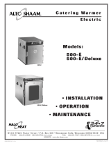
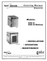
The Wittco 1220-105 series of holding, transporting and serving cabinets provide an efficient method and holding,
transporting, displaying, and serving prepared food product for either self-service grab and go programs or operator
serviced programs. Concessions, chain operators, schools, restaurants, correctional facilities and convenience store
operators are all users of these dependable units.
This manual has been produced to provide persons responsible for the operation and maintenance of the equipment
with a simple but comprehensive understanding of its proper use. We recommend that this manual be read and
understood prior to placing the cabinet in operation.
As with any piece of food service equipment, this unit will require a minimum of care and maintenance. Suggestions
for this procedure are contained in this manual and should become a regular part of the operation of the unit.
NOTE: The unit should be thoroughly cleaned in accordance with the instructions contained in this manual.
It is recommended that prior to placing the unit into operation that it be pre-heated at the highest temperature setting
for a period of 30-45 minutes.
Should repair or adjustment of the unit become necessary, we suggest that procedures described in this manual be
followed. The operator may also contact the authorized Wittco service agency. If the needed repair occurs during the
warranty period, prior authorization is required from Wittco by the service company before the work is done.
It is our sincere desire that you obtain the maximum benefit from your Wittco holding and serving system. If at any
time questions arise or additional information is required, contact Wittco at 800 367-8413.
DESCRIPTION
The Wittco 1220-105 series provides an efficient means of transporting, holding, displaying and serving a variety of
prepared foods at proper serving temperatures. These units are provided with individual thermostatically controlled
heated compartments, an ambient holding compartment, and top mounted heated serving wells. The holding
compartments accommodate the standard 12 X 20 steam table pans of depths up to six inches.
UNCRATING
Each Wittco unit is packed in either a cardboard carton and skidded or crate and skid depending upon the model. When
the unit is received by the operator, the carton should immediately be inspected for any sign of visible exterior damage.
If carton or crate is punctured or dented, it may be an indication that the cabinet has sustained concealed freight
damage.
It is very important that any evidence of damage be noted on the Bill of Lading at the time of receipt.

UNPACKING THE UNIT
1. Remove the cardboard carton from the skid or the wood crating from the skid depending upon the model.
2. Remove all exterior packaging and protective materials from the unit.
3. Carefully remove the unit from the skid.
4. Open all doors to the holding compartments and remove all interior packaging materials.
5. Pre-heat the unit by turning all the thermostats to their highest temperature for a period of 30-45 minutes.
ELECTRICAL REQUIREMENTS
The Wittco 1220-105 series are factory wired for either 110/120 volt or 208/240 volt, single phase operation
depending upon the model. All 110/120 volt units are equipped with an 8 foot cord and NEMA 5-15 plug as
standard equipment. All 208/240 units are equipped with an 8 foot cord and NEMA plug compatible to the total
wattage load depending upon the model.
CAUTION: Verify that the power source matches the data plate on the located on the unit and the plug
configuration before the connection is made.
OPERATION
The control panels of the 1220-105 series contain dual operating indicator lights for the holding compartments,
single operating indicator light for each top mounted heated well, full range thermostat for each holding
compartment and top mounted heated well, and dial thermometer for each holding compartment.
After the unit has been connected to an appropriate power source the operator will notice that the red indicator
light(s) are illuminated. This light(s) will continue to be on as long as the unit is connected to the power source.
HEATED HOLDING COMPARTMENTS - Rotate the thermostat knobs so that they point to the number 5. This
will cause the heating elements to start heating. When this occurs the amber indicator light(s) will be illuminated.
This light(s) will stay on as long as the heating element(s) is engaged. Once the predetermined temperature is
achieved, the heating element(s) will begin to cycle. During the cycling period the amber light(s) will turn on and
off.
As the element(s) is heating, thermometer will begin to move and indicate the interior temperature of the unit. At
the number 5 setting the thermometer(s) should indicate an average temperature of approximately 150 degrees F.
HEATED TOP MOUNTED SERVING WELLS - Rotate the thermostat knob so that it point to the number 5. This
will cause the well heating element to start heating. When this occurs the red single indicator light will illuminate.
This light will stay on as long as the heating element is engaged. Once the predetermined temperature is achieved,
the heating element will begin to cycle. During the cycling period the red light will turn on and off.

NOTE: The temperature in any heated cabinet will fluctuate as the heating element cycle on and off. The
thermostat setting will provide an average air temperature in the cabinet. However, the operator should
always monitor the food product to insure that it remains at the proper temperature.
REMEMBER - THE GREATER THE THERMOSTAT NUMBER SETTING THE HIGHER THE
CABINET TEMPERATURE AND THE LOWER THE THERMOSTAT NUMBER SETTING THE
LOWER THE TEMPERATURE.
CLEANING
Wittco's 1220-105 series are constructed from heavy duty stainless steel. It is highly recommended that when
cleaning only a mild soap and water solution be used to clean. Never use harsh chemicals or abrasive pads to
clean the cabinet.
REPLACEMENT OF ELECTRICAL COMPONENTS
It is highly recommended that only Wittco Foodservice Equipment replacement parts be used to insure
compatibility of component parts in the operation of the unit.
IMPORTANT NOTE: WHEN REPLACING ANY OF THE ELECTRICAL COMPONENTS IN
THE 1220-105 SERIES (WITH THE EXCEPTION OF THE HOLDING
COMPARTMENT HEATING ELEMENTS) IT IS NECESSARY TO
REMOVE THE ENTIRE TOP OF THE UNIT CONTAINING THE TOP
MOUNTED HEATED WELLS.
REMOVING THE UNIT TOP CONTAINING THE TOP HEATED
SERVING WELLS
1. DISCONNECT THE UNIT FROM ITS POWER SOURCE.
2. Remove all of the top side mounted retaining screws securing the top to the unit.
3. Slowly lift the entire top from unit in an start upward movement. This will expose all interior wiring and
components attached between the top mounted wells and cabinet base.
4. When the lower bottom surface of the top mounted heated wells clears the top surface of the cabinet, turn
the top one-third turn and rest the top assembly directly on the cabinet top surface.

THERMOSTAT REPLACEMENT
1. DISCONNECT THE UNIT FROM ITS POWER SOURCE.
NOTE: REFER TO REMOVING THE UNIT TOP CONTAINING THE TOP HEATED
SERVING WELLS SECTION.
2. Remove the black thermostat knob from the control panel by loosening the "L-end" screws that holds
it to the thermostat stem.
NOTE: PRIOR TO LOOSENING THE "L-end" SCREWS, TURN THE BLACK
THERMOSTAT KNOB SO THAT THE ARROW ON THE KNOB IS IN THE "OFF"
POSITION
3. Notice the arrangement and connection of all electrical leads and refer to the wiring diagrams for
reference.
4. Disconnect the wire leads connected to the thermostat.
5. Loosen the screws holding the temperature sensing bulb located at the interior top of the holding
compartment.
6. Pull the thermostat sensing bulb through the access hole located in the top of the cabinet.
7. Remove the two screws on the front of the control panel that hold the thermostat in place and
remove it along with me temperature sensing bulb.
8. Install the replacement thermostat and temperature sensing bulb following the reverse of the above
procedure.
9. Reinstall the cabinet top cover and screws.
10. Reconnect the unit to the power source and test.
INDICATOR LIGHT REPLACEMENT
1. DISCONNECT THE UNIT FROM ITS POWER SOURCE.
NOTE: REFER TO REMOVING THE UNIT TOP CONTAINING THE TOP HEATED
SERVING WELLS SECTION.
2. Remove the top cover by removing the retaining screws and lifting the cover off the unit to expose
the indicator light.

3. Notice the arrangement and connection of all electrical leads and refer to the wiring diagrams for
reference.
4. Disconnect the wire leads connected to the indicator light.
5. Remove the indicator light by pushing the retaining clips inward on the indicator light mounting and
remove the indicator light from the front of the control panel.
6. Install the replacement indicator light in the reverse order of the above.
7 . Reinstall the top cover of the unit.
8. Reconnect the unit to the power source and test.
HEATING ELEMENT REPLACEMENT
1. DISCONNECT THE UNIT FROM ITS POWER SOURCE.
2. Open the door to the cabinet.
3. Remove the bottom mounted element cover.
4. Remove the retaining screws securing the element to the interior rear of the cabinet.
5. Notice the arrangement and connection of all wire leads and refer to the wiring diagrams for reference.
6. Carefully pull the element from its housing until the electrical lead wire connections are visible.
7. Disconnect the defective element lead wires at their connection points.
8. Connect the replacement element lead wires to the cabinet lead wires.
9. Tuck the residual wire back through the wire housing access hole until the replacement element
housing is against the interior rear wall.
10. Reinstall the element retaining screws.
11. Reinstall the top cover.
12. Reconnect the unit to its power source and test.

THERMOMETER REPLACEMENT
1. DISCONNECT THE UNIT FROM ITS POWER SOURCE.
NOTE: REFER TO REMOVING THE UNIT TOP CONTAINING THE TOP HEATED
SERVING WELLS SECTION.
2. Remove the top cover by removing the retaining screws and lifting the top cover off the cabinet to
expose the thermometer.
3. Identify and remove the thermometer sensing bulb screws and retaining clips located in the interior top
of the unit. Pull the thermometer sensing bulb through the access hole located in the top of the unit.
4. Remove the retaining nuts which secure the thermometer to the housing located on the back of the
control panel.
5. Remove the thermometer by pushing it from the rear through the control panel front.
6. Install the replacement thermometer following the reverse of the above procedure.
7. Reconnect the unit to its power source and test.
TOP MOUNTED WELL REPLACEMENT
(Including well insert heating element)
1. DISCONNECT THE UNIT FROM ITS POWER SOURCE.
NOTE: REFER TO REMOVING THE UNIT TOP CONTAINING THE TOP HEATED
SERVING WELLS SECTION.
2. Remove the top cover by removing the retaining screws and lifting the top cover off the cabinet to
expose the heated wells.
3. Remove the well insert retaining screws located on the interior sides of the well insert.
4. Notice the arrangement and connection of all wire leads and refer to the wiring diagrams for reference.
5. Disconnect all wire leads from the well insert at their connection points.
6. Push the well insert through the top from the bottom.
7. Install the replacement well insert in the reverse order of the above.
8. Reinstall top & reconnect the unit to its power source and test.


WITTCO FOODSERVICE EQUIPMENT INC.
REPLACEMENT PARTS LIST
WITTCO SERIES - HOLDING/TRANSPORT/SERVING UNITS 6/30/98
WITTCO
MODEL NUMBER AND QUANTITY REQUIRED
PART NO. PART DESCRIPTION
1220-105
122U-1U5-2 1220-105-3 1220-105-4
WP-239-105E BUMPER, ALUMINUM EXTRUSION ONLY (NO VINYL) 1
WP-239-105-2R BUMPER, ALUMINUM EXTRUSION ONLY (NO VINYL)
1
WP-239-105-3E BUMPER, ALUMINUM EXTRUSION ONLY (NO VINYL)
1
WP-239-105-4E BUMPER, ALUMINUM EXTRUSION ONLY (NO VINYL)
1
WP-239-105V BUMPER, BLACK VINYL ONLY (NO EXTRUSION) 1
WP-239-105-2V BUMPER, BLACK VINYL ONLY (NO EXTRUSION)
1
WP-239-105-3V BUMPER, BLACK VINYL ONLY (NO EXTRUSION)
1
WP-239-1U5-4V BUMPER, BLACK VINYL ONLY (NO EXTRUSION)
1
WP-079 CARD HOLDER, 3" x 5" 1 1 1 1
WP-114-2R CASTER 2" HEAVY DUTY RIGID 2 2
WP-114-2S CASTER 2" HEAVY DUTY SWIVEL W/BRAKE 2 2
WP-114-3R CASTER 3" HEAVY DUTY RIGID 2 2
WP-114-3S CASTER 3" HEAVY DUTY SWIVEL W/BRAKE 2 2
WP-114-4R CASTER 4" HEAVY DUTY RIGID 2 2
WP-114-4S CASTER 4" HEAVY DUTY SWIVEL W/BRAKE 2 2
WP-114-5R CASTER 5" HEAVY DUTY RIGID 2 2 2 2
WP-114-5S CASTER 5" HEAVY DUTY SWIVEL W/BRAKE 2 2 2 4
WT-114-6R CASTER 6" HEAVY DUTY RIGID 2 2 2 2
WP-114-6S CASTER 6" HEAVY DUTY SWIVEL W/BRAKE 2 2 2 4
WP-114-6HR CASTER 6" HI-MODULUS RIGID 2 2 2 2
Wr-114-6HS CASTER 6" HI-MODULUS SWIVEL W/BRAKE 2 2 2 . 4
CONTROL PANEL DECAL TOP/BOTTOM HEAT
WP-146-4105-1 (BLACK)
WP-146-4105-2 CONTROL PANEL DECAL - TOP HEAT ONLY (BLACK)
WP-146-4105-3 CONTROL PANEL DECAL - BLANK (BLACK)
CONTROL PANEL DECAL - BOTTOM HEAT ONLY
WP-146-4105-4 (BLACK)
WP-052 CORD, 8 FT. 1
WP-247 CORD, 10 FT.
1 1 1

MODEL NUMBER AND QUANTITY REQUIRED
WITTCO
PART NO.
PART DESCRIPTION
1220-105 1220-105-2 1220-105-3 1220-105-4
AD-650 CORD WRAP 1 1 1 1
WP-035 DOOR, (NO HARDWARE) 1 2 3 4
WP-107 DOOR LATCH COMPLETE W/CATCH 1 2 3 4
WP-104-1 ELEMENT, 600 WATT 120 VOLT 1 2 3 4
WP-104-2 ELEMENT, 600 WATT 208-240 VOLT 1 2 3 4
WP-118 ELEMENT, 750 WATT 120 VOLT (SERVING WELL) 1 2 3 4
ELEMENT, 750 WATT 208-240 VOLT
WP-144 (SERVING WELL) 1 2 3 4
WP-850-120 ELEMENT, 850 WATT 120 VOLT (SERVING WELL) 1 2 3 4
ELEMENT, 850 WATT 208-240 VOLT
WP-850-240 (SERVING WELL) 1 2 3 4
WP-182 ELEMENT CLIP 1 i 3 4
WP-181 ELEMENT COVER 1 1 3 4
WP-092-7 GASKET, DOOR ALUMINUM EXTRUSION (ONLY) 1 2 3 4
WP-302 GASKET, DOOR (BLACK) BY THE FT. 7' 14' 21' 28'
WP-108 HANDLE, LIFT SIDE MOUNTED 4
WP-111 HINGE, DOOR 2 4 6 8
WP-106-1 LIGHT, INDICATOR DUAL 125 VOLT (AMBER/RED) 1 2 3 4
WP-106-2 LIGHT, INDICATOR DUAL 250 VOLT (AMBER/RED) 1 2 3 4
WP-040 LIGHT, INDICATOR ROUND 125 VOLT 1 2 3 4
AD-226-0000-0 LIGHT, INDICATOR ROUND 250 VOLT 1 2 3 4
WP-084 RACKS, INT. SIDE (HOLDS 4-4" PANS) 2 4 6 8
WP-085 RACKS, INT. SIDE (HOLDS 3-6" PANS) 2 4 6 8
WP-211 RACKS, INT.SIDE (HOLDS 7-2 '/2 " PANS) 2 4 6 8
WP-305 RACK, SIDE RETAINING BOLTS 8 16 24 32
WP-006-1 STRAIN RELIEF AT POWER CORD 1
WP-U06-312 STRAIN RELIEF AT POWER CORD
1
WP-006-6 STRAIN RELIEF AT POWER CORD (METAL)
1 1
WP-109 THERMOMETER, DIAL TYPE 1 2 3 4
WP-093 THERMOMETER BULB HOLDER 1 2 3 4

MODEL NUMBER AND QUANTITY REQUIRED
WITTCO
PART NO.
PART DESCRIPTION
1220-105 1220-1U5-2 1220-105-3 1220-105-4
WP-110 THERMOSTAT, W/OUT KNOB 1 2 3 4
AD-242 THERMOSTAT KNOB 1 2 3 4
WP-120 THERMOSTAT FOR SERVING WELL 1 2 3 4
AD-242 THERMOSTAT KNOB FOR SERVING WELL 1 2 3 4
WP-089 THERMOSTAT BULB HOLDER 2 4 6 8
WP-038 WELL COMPLETE WITH EI.EMENT & THERMOSTAT 1 2 3 4
/