Emerson Process Management 51000 User manual
- Type
- User manual
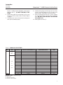
Emerson Process Management 51000 is a low flow control valve designed for demanding applications where space is limited. It provides a compact and lightweight alternative to flanged body globe valves, making installation easier. The 51000 is suitable for a wide range of pressures, temperatures, and other application specifications, ensuring reliable performance in various industrial settings.
Emerson Process Management 51000 is a low flow control valve designed for demanding applications where space is limited. It provides a compact and lightweight alternative to flanged body globe valves, making installation easier. The 51000 is suitable for a wide range of pressures, temperatures, and other application specifications, ensuring reliable performance in various industrial settings.


-
 1
1
-
 2
2
-
 3
3
-
 4
4
-
 5
5
-
 6
6
-
 7
7
-
 8
8


Emerson Process Management 51000 User manual
- Type
- User manual
Emerson Process Management 51000 is a low flow control valve designed for demanding applications where space is limited. It provides a compact and lightweight alternative to flanged body globe valves, making installation easier. The 51000 is suitable for a wide range of pressures, temperatures, and other application specifications, ensuring reliable performance in various industrial settings.
Ask a question and I''ll find the answer in the document
Finding information in a document is now easier with AI
Other documents
-
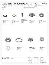 T & S Brass & Bronze Works B-0290-K Datasheet
-
Emerson FIELDVUEDVC2000 Quick start guide
-
-
Fisher & Paykel 81823 User guide
-
-
-
Jordan Valve Mark 675 Series Maintenance Manual
-
-
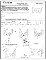 Riverside Furniture 51401 Assembly Instructions
-

