Page is loading ...

LED Orbit I
ORDERCODE 41360

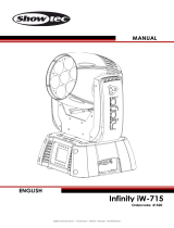
Congratulations!
You have bought a great, innovative product from Showtec.
The Showtec LED Orbit I brings excitement to any venue. Whether you want simple plug-&-play action or a
sophisticated DMX show, this product provides the effect you need.
You can rely on Showtec, for more excellent lighting products.
We design and manufacture professional light equipment for the entertainment industry.
New products are being launched regularly. We work hard to keep you, our customer, satisfied.
For more information: iwant@showtec.info
You can get some of the best quality, best priced products on the market from Showtec.
So next time, turn to Showtec for more great lighting equipment.
Always get the best -- with Showtec !
Thank you!

1
2
2
3
3
5
5
6
7
7
7
8
9
10
10
10
11
13
13
14
14
14
14
14
15
Showtec
Showtec LED Orbit I™ Product Guide
Warning..…...................................................................................………………………………………………………..
Safety-instructions…………………………………………………………………………………………………………
Operating Determinations………………………………………………………………………………………………
Rigging……………………………………………………………………………………………………………………...
Description..…..............................................................................……….………………………………………………
Features and Overview ………………………………...….……………….………….……….……….……………...
Backside…………………………………………………...…...….……………….…………………...….………………
Set Up and Operation.....................................................................……..………………………………………………
One LED Orbit I ............................................................................……………………………………………………
Multiple LED Orbits..............................................................................……………………………………………….
Beam Angles……………………………………………………………………………………………………………….
DMX Protocol………...................................................…………………………………………………………………
Control Panel….............……....................................…………………………………………………………………..
Control Mode........................................…………………………………………………………………………………
DMX addressing...................................………………………………………………….…………………………..….
Control panel functions...................................………………………………………………………………………..
Menu Functions Explained.............................…………………………………………………………………………
DMX 512 Channel settings for LED Orbit I…………………………………………………………………………….
Maintenance...................................................................................………..………….…….…………………………..
Changing the Fuse........................................................................…………………….………………………..…...
Troubleshooting............................................................................………………….………………….………………...
No Light, No Movement - All Products............................................………………….…………………………....
No Response…………....................................................................………………….……………………………….
Product Specifications.................................................................……………….…….………………………………...

2
WARNING
FOR YOUR OWN SAFETY, PLEASE READ THIS USER MANUAL CAREFULLY
BEFORE YOUR INITIAL START-UP!
SAFETY INSTRUCTIONS
Every person involved with the installation, operation and maintenance of this device have to:
- be qualified
- follow the instructions of this manual
Before your initial start-up, please make sure that there is no damage caused by transportation. Should there
be any, consult your dealer and do not use the device.
To maintain perfect condition and to ensure a safe operation, it is absolutely necessary for the user to follow
the safety instructions and warning notes written in this manual.
Please consider that damages caused by manual modifications to the device are not subject to warranty.
This device contains no user-serviceable parts. Refer servicing to qualified technicians only.
IMPORTANT:
The manufacturer will not accept liability for any resulting damages caused by the non-
observance of this manual or any unauthorized modification to the device.
Never let the power-cord come into contact with other cables! Handle the power-cord and all
connections with the mains with particular caution!
Never remove warning or informative labels from the unit.
Never use anything to cover the ground contact.
Do not insert objects into air vents.
Do not connect this device to a dimmerpack.
Never look directly into the light source
Do not switch the device on and off in short intervals, as this would reduce the lamp’s life.
Do not touch the device’s housing bare-handed during its operation (housing becomes very hot).
Only use device indoor, avoid contact with water or other liquids.
Avoid flames and do not put close to flammable liquids or gases.
Always keep case closed while operating.
Always allow free air space of at least 50 cm around the unit for ventilation.
Always disconnect power from the mains, when device is not used, before cleaning or when
replacing lamp! Only handle the power-cord by the plug. Never pull out the plug by tugging the
power-cord.
Make sure that the available voltage is not higher than stated on the rear panel.
Make sure that the power-cord is never crimped or damaged. Check the device and the power-
cord from time to time.
CAUTION!
Keep this device away from rain and moisture!
Unplug mains lead before opening the housing!
CAUTION! Be careful with your operations.
With a dangerous voltage you can suffer
a dangerous electric shock when touching the wires!

3
If device is dropped or struck, disconnect mains power supply immediately. Have a qualified
engineer inspect for safety before operating.
If the device has been exposed to drastic temperature fluctuation (e.g. after transportation), do not
switch it on immediately. The arising condensation water might damage your device. Leave the
device switched off until it has reached room temperature.
If your Showtec device fails to work properly, discontinue use immediately. Pack the unit securely
(preferably in the original packing material), and return it to your Showtec dealer for service.
For replacement use lamps and fuses of same type and rating only.
Allow time to cool down, before replacing lamp.
This device falls under protection class I. Therefore it is essential to connect the yellow/green
conductor to earth.
During the initial start-up some smoke or smell may arise. This is a normal process and does not
necessarily mean that the device is defective.
Repairs, servicing and electric connection must be carried out by a qualified technician.
WARRANTY: Till one year after date of purchase.
OPERATING DETERMINATIONS
This device is not designed for permanent operation. Consistent operation breaks will ensure that the device
will serve you for a long time without defects.
The minimum distance between light-output and the illuminated surface must be more than 0.5 meter.
If this device is operated in any other way, than the one described in this manual, the product may suffer
damages and the warranty becomes void.
Any other operation may lead to dangers like short-circuit, burns, electric shock, lamp explosion, crash etc.
You endanger your own safety and the safety of others!
Rigging
Please follow the European and national guidelines concerning rigging, trussing and all other
safety issues.
Do not attempt the installation yourself !
Always let the installation be carried out by an authorized dealer !
Procedure:
If the projector is lowered from the ceiling or high joists, professional trussing systems have to be used.
Use a clamp to mount the projector, with the mounting-bracket, to the trussing system.
The projector must never be fixed swinging freely in the room.
The installation must always be secured with a safety attachment, e.g. an appropriate safety net or
safety-cable.
When rigging, derigging or servicing the projector, always make sure, that the area below the
installation place is blocked and staying in the area is forbidden.
The LED Orbit I can be placed on a flat stage floor or mounted to any kind of truss by a clamp.
Improper installation can cause serious damage to people and property !
CAUTION ! EYEDAMAGES !.
Avoid looking directly into the light source.
(meant especially for epileptics) !

4
Connection with the mains
Connect the device to the mains with the power-plug.
Always pay attention, that the right color cable is connected to the right place.
International
EU Cable
UK Cable
US Cable
Pin
L
BROWN
RED
YELLOW/COPPER
FASE
N
BLUE
BLACK
SILVER
NUL
YELLOW/GREEN
GREEN
GREEN
EARTH
Make sure that the device is always connected properly to the earth!

5
Description of the device
Features
The Showtec LED Orbit I is a one-arm moving-head with high output and great effects.
• 36x 1W LEDs (12x Red, 12x Green, 12x Blue)
• DMX-control via standard DMX-controller
• 12 DMX-control channels required
• Strobe-effect with adjustable speed (1 - 25 flashes/sec.)
• Beam Angle 50 º
• 16-bit resolution
• RGB color mixing
• Dimmer 0-100%
• Master/Slave function
• Stand alone function
• Pan 0º -- 540º
• Tilt 0º -- 270º
• Power select 110V/ 220V
• Fuse ø5 X20 6A / 250V
1
Overview
2
3
Fig. 1
1) 36X 1W LED
2) Display
3) Menu / Select buttons

6
Backside
4 5 6 7 8 9 Fig. 2
4) Ventilation
5) Power Select 110V/220V
6) IEC power connector + Fuse ø5 X20 6A / 250V
7) Ground connection
8) DMX signal connector (OUT)
9) DMX signal connector (IN)

7
Set Up and Operation
Follow the directions below, as they pertain to your preferred operation mode.
Before plugging the unit in, always make sure that the power supply matches the product specification
voltage. Do not attempt to operate a 120V specification product on 230V power, or vice versa.
One LED Orbit I
1. Fasten the moving head onto firm trussing (Use a proper clamp fastened onto the LED Orbit I ).
Leave at least 1 meter on all sides for air circulation.
2. Plug one end of the electric mains power cord into the IEC socket on the unit.
Then plug the other end of the cord into a proper electric power supply socket.
3. To set the program to be played, press:
4. Always use a safety cable. Hold for 3 sec
When you plug in the device, the display shows A001. To enter the Main menu, press M/enter for 5 seconds
Multiple LED Orbits
1. Fasten the effect light onto firm trussing (Use a proper clamp fastened onto the LED Orbit I ).
Leave at least 1 meter on all sides for air circulation.
2. Use a 3-p XLR cable to connect the LED Orbits and other devices.
The pins:
1. Earth
2. Signal -
3. Signal +
3. Link the units as shown in (figure 3), Connect a DMX signal cable from the first unit's DMX "out" socket to
the second unit's "in" socket. Repeat this process to link the second, third, and fourth units.
4. Supply electric power: Plug electric mains power cords into each unit's IEC socket, then plug the other
end of the mains power cord into proper electric power supply sockets, starting with the first unit. Do not
supply power before the whole system is set up and connected properly.
Multiple LED Orbits Set Up
Fig. 3
Note : Link all cables before connecting electric power

8
Beam Angles

9
DMX Protocol
Channel 1 – Strobe
0-7
Shutter open / Full beam
8-255
Strobe effect, from slow to fast (0-10 flashes/sec.)
Channel 2 – Red
0-255
Gradual adjustment Red from 0 – 100%
Channel 3 – Green
0-255
Gradual adjustment Green from 0 – 100%
Channel 4 – Blue
0-255
Gradual adjustment Blue from 0 – 100%
Channel 5 – Built-in Programs
0-255
Play one of the built-in color settings
Channel 6 – Speed
0-255
Gradual adjustment from color change speed
Channel 7 - Horizontal movement (Pan)
Push the slider up, in order to move head horizontally (PAN).
Gradual head adjustment from one end of the slider to the other (0-255, 128-center).
The head can be turned by 540° and stopped at any position you wish.
Channel 8 - Vertical movement (Tilt)
Push the slider, up in order to move head vertically (TILT).
Gradual head adjustment from one end of the slider to the other (0-255, 128-center).
The head can be turned by 280° and stopped at any position you wish.
Channel 9 - Pan fine 16 bit
Channel 10 - Tilt fine 16 bit
The LED Orbit I can be operated with a controller in control mode or without the controller in stand-alone
mode.

10
Control Panel
When the indicator light is on, means the LED Orbit I is working
Fig. 6
A. Display D. Up Button
B. LED E. Down Button
C. [EXIT] Button F. [M/ENTER] Button
Control Mode
The fixtures are individually addressed on a data-link and connected to the controller.
The fixtures respond to the DMX signal from the controller. (When you select the DMX address and save it, the
controller will display the saved DMX address the next time.)
DMX Addressing
The control panel on the front side of the base allows you to assign the DMX fixture address, which is the first
channel from which the LED Orbit will respond to the controller.
Please note when you use the controller, the unit has 10 channels.
When using multiple LED Orbits, make sure you set the DMX addresses right.
Therefore, the DMX address of the first LED Orbit should be 1(A001); the DMX address of the second LED Orbit
should be 1+10=11 (A011); the DMX address of the third LED Orbit should be 11+10=21 (A021), etc.
Please, be sure that you don’t have any overlapping channels in order to control each LED Orbit correctly.
If two or more LED Orbits are addressed similarly, they will work similarly.
For address settings, please refer to the instructions under ”Addressing’ (menu )
Controlling:
After having addressed all LED Orbit fixtures, you may now start operating these via your lighting controller.
Note: After switching on, the LED Orbit will automatically detect whether DMX 512 data is received or not. If
there is no data received at the DMX-input, the “LED “ on the control panel will not flash.
The problem may be:
- The XLR cable from the controller is not connected with the input of the LED Orbit.
- The controller is switched off or defective, the cable or connector is detective, or the signal wires are
swapped in the input connector.
Note: It’s necessary to insert a XLR termination plug (with 120 Ohm) in the last fixture in order to ensure proper
transmission on the DMX data link.

11
Overview Control Panel Functions
Press Exit to return to the main menu

12
Menu Functions Explained
DMX Address selection
Reset unit, the display will show for 30 seconds
Working Speed selection Maximum working speed
80% of the working speed
Channel selection 16-bit available for Pan (X) and Tilt (Y)
16-bit not available for Pan (X) and Tilt (Y)
Channel Test selection. First select the channel, then press enter to test the desired channel
Time Menu LED lifetime, hold enter for 5 seconds to reset time to 0
Unit working hours
Display open
Display main Menu
Display close after 10 seconds
Display inverse
Display normal
Tilt (Y) direction selection Tilt in positive direction
Tilt in negative direction
Pan (Y) direction selection Pan in positive direction
Pan in negative direction

13
Addressing
With this menu you can set the DMX address.
- DMX addressing
1) Press:
Hold for 3 sec Push to select address
2) The first device should be set to ADDR A001.
DMX 512 Channel settings for LED Orbit I
Light No.
Start Channels
Light No.
Start Channels
1
A001
41
A401
2
A011
42
A411
3
A021
43
A421
4
A031
44
A431
5
A041
45
A441
6
A051
46
A451
7
A061
47
A461
8
A071
48
A471
9
A081
49
A481
10
A091
50
A491
11
A101
51
A501
12
A111
52
A511
13
A121
53
A521
14
A131
54
A531
15
A141
55
A541
16
A151
56
A551
17
A161
57
A561
18
A171
58
A571
19
A181
59
A581
20
A191
60
A591
21
A201
61
A601
22
A211
62
A611
23
A221
63
A621
24
A231
64
A631
25
A241
65
A641
26
A251
66
A651
27
A261
67
A661
28
A271
68
A671
29
A281
69
A681
30
A291
70
A691
31
A301
71
A701
32
A311
72
A711
33
A321
73
A721
34
A331
74
A731
35
A341
75
A741
36
A351
76
A751
37
A361
77
A761
38
A371
78
A771
39
A381
79
A781
40
A391
80
A791

14
Maintenance
The Showtec LED Orbit I requires almost no maintenance. However, you should keep the unit clean.
Otherwise, the fixture’s light-output will be significantly reduced. Disconnect the mains power supply, and
then wipe the cover with a damp cloth. Do not immerse in liquid. Do not use alcohol or solvents.
The lens will require weekly cleaning, as smoke-fluid tends to build up residues, reducing the light-output
very quickly.
Please clean internal components once a year with a light brush and vacuum cleaner.
Keep connections clean. Disconnect electric power, and then wipe the connections with a damp cloth.
Make sure connections are thoroughly dry before linking equipment or supplying electric power.
The operator has to make sure that safety-relating and machine-technical installations are to be inspected
by an expert after every four years in the course of an acceptance test.
The operator has to make sure that safety-relating and machine-technical installations are to be inspected
by a skilled person once a year.
The following points have to be considered during the inspection:
1. All screws used for installing the device or parts of the device have to be tightly connected and must
not be corroded.
2. There may not be any deformations on housings, fixations and installation spots.
3. Mechanically moving parts like axles, eyes and others may not show any traces of wearing.
4. The electric power supply cables must not show any damages or material fatigue.
Replacing a Fuse
Power surges, short-circuit or inappropriate electrical power supply may cause a fuse to burn out. If the fuse
burns out, the product will not function whatsoever. If this happens, follow the directions below to do so.
1. Unplug the unit from electric power source.
2. Insert a flat-head screwdriver into a slot in the fuse cover. Gently pry up the fuse cover.
3. Remove the used fuse. If brown or unclear, it is burned out.
4. Insert the replacement fuse into the holder where the old fuse was. Reinsert the fuse cover. Products are
packed with a replacement fuse. If your replacement fuse is missing, a new one can be purchased at an
electric appliance store. Be sure to use a fuse of the same type and specification. See the product
specification label for details.
Troubleshooting
No Light, No Movement - All Products
This troubleshooting guide is meant to help solve simple problems. If a problem occurs, carry out the steps
below in sequence until a solution is found. Once the unit operates properly, do not carry out following steps.
If the light effect does not operate properly, refer servicing to a technician.
Response: Suspect three potential problem areas: the power supply, the lamp, the fuse.
1. Power supply. Check that the unit is plugged into an appropriate power supply.
2. The LEDs. Return the LED Orbit 1 LED to your Showtec dealer.
3. The fuse. Replace the fuse. See page 14 for replacing the fuse.
No Response to DMX
Response: Suspect the DMX cable or connectors, a controller malfunction, a light effect DMX card
malfunction.
1. Check the DMX cable: Unplug the unit; change the DMX cable; then reconnect to electrical power. Try
your DMX control again.
2. Determine whether the controller or light effect is at fault. Does the controller operate properly with other
DMX products ? If not, take the controller in for repair. If so, take the DMX cable and the light effect to a
qualified technician.

15
Product Specification
Model: Showtec LED Orbit I
Voltage: 230V-50Hz (CE)
Power Select 110V/220V
Fuse: Fuse ø5 X 20 6A / 250V
Dimensions: 359x300x365mm (LxWxH)
Weight: 7,68 kg
Operation and Programming
Signal pin OUT : pin 1 earth, pin 2 (-), pin 3 (+)
Set Up and Addressing : LED control panel
Pan / Tilt 8 or 16 bit
DMX channels: 10
Signal input 3-pin XLR male
Signal output 3-pin XLR female
Control: Automatic and DMX remote ON / OFF
Electro-mechanical effects
Dimmer : 0 – 100% linear dimmer
Strobe-effect with variable speed (1 flash -- 10 flashes/sec.)
DMX-control via standard DMX-controller
Pan 0º -- 540º
Tilt 0º -- 270º
Wheel control : auto-electronic reset
Cooling: Fan cooled
Design and product specifications are subject to change without prior notice.
Website: www.Highlite.nl
Email: service@highlite.nl

2007
Showtec.
/