Page is loading ...

IN-E-HyLab-V4_11
Rotronic AG
Bassersdorf, Switzerland
Document code Unit
Instruction Manual
Document Type
HygroLab bench top indicator version 4:
instruction manual
Document title
Page 1 of 51
© 2006; Rotronic AG IN-E-HyLab-V4_11
HygroLab Bench Top Indicator version 4
Instruction Manual

IN-E-HyLab-V4_11
Rotronic AG
Bassersdorf, Switzerland
Document code Unit
Instruction Manual
Document Type
HygroLab bench top indicator version 4:
instruction manual
Document title
Page 2 of 51
© 2006; Rotronic AG IN-E-HyLab-V4_11
Table of contents
1 Overview ....................................................................................................................................3
2 General description ..................................................................................................................4
2.1 Power requirements................................................................................................................4
2.2 Probes and probe inputs.........................................................................................................4
2.3 Analog outputs (optional) ........................................................................................................6
2.4 Serial interface (HygroLab 2 and 3)........................................................................................7
2.5 Optional Ethernet (TCP/IP) interface (HygroLab 2 and 3)......................................................9
3 Optional configuration and communication software ........................................................10
4 How to configure the HygroLab ............................................................................................10
4.1 Internal service connector (HygroLab configuration)............................................................10
4.2 Baud rate compatibility requirements ...................................................................................11
4.3 Ethernet local area network ..................................................................................................11
4.4 RS-485 multi-drop network (HygroLab 2 and 3)...................................................................12
4.5 Selection of the probe supply voltage (main PCB) ...............................................................14
5 Operation.................................................................................................................................14
5.1 Unit system ...........................................................................................................................15
5.2 Display and keypad...............................................................................................................15
5.3 Probe Input Selection............................................................................................................16
6 Function menu ........................................................................................................................16
6.1 CALCULATE (HygroLab 2 and 3).........................................................................................17
6.2 MODE (HygroLab 3) .............................................................................................................18
6.3 DISPLAY (HygroLab 2 and 3)...............................................................................................21
6.4 ADJUST M.PT ......................................................................................................................21
6.5 ADJUST 1PT.........................................................................................................................23
6.6 ADJUST REF........................................................................................................................24
6.7 PROBE..................................................................................................................................25
6.8 SETTINGS ............................................................................................................................25
6.9 SYS STATUS........................................................................................................................26
7 Error and status messages....................................................................................................26
8 Connectors..............................................................................................................................27
9 Environmental limits ..............................................................................................................28
10 Maintenance of the ROTRONIC probes................................................................................29
11 Specifications..........................................................................................................................30
12 Practical advice for measuring humidity .............................................................................31
13 Probe calibration basics ........................................................................................................31
13.1 Temperature calibration ........................................................................................................31
13.2 Humidity calibration...............................................................................................................32
14 Humidity definitions ...............................................................................................................33
15 Dew point accuracy ................................................................................................................36
16 ASCII communications protocol ...........................................................................................37
17 Water activity measurement..................................................................................................40
17.1 Water activity: definition and applications.............................................................................40
17.2 Using the HygroLab 2 or 3 to measure water activity...........................................................42
17.3 Principle of measurement .....................................................................................................43
17.4 General recommendations....................................................................................................44
17.5 Using the AwE mode (HygroLab 3) ......................................................................................45
17.6 Using the AwQuick mode (HygroLab 3) ...............................................................................47
18 Accessories for the HygroLab...............................................................................................50
19 Document releases.................................................................................................................51

IN-E-HyLab-V4_11
Rotronic AG
Bassersdorf, Switzerland
Document code Unit
Instruction Manual
Document Type
HygroLab bench top indicator version 4:
instruction manual
Document title
Page 3 of 51
© 2006; Rotronic AG IN-E-HyLab-V4_11
Applicability:
This manual is valid for all instruments with firmware version 4.x, where 4.x can be 4.0, 4.1, etc.
(see Function Menu, SYS STATUS). Changes to the last digit of the version number reflect minor
firmware changes that do not affect the manner in which the instrument should be operated.
Note: Instrument configuration requires a PC with the optional ROTRONIC HW4 software version
1.2.2 or higher. Instructions for using the software are not included in this manual. These
instructions are shipped separately on the software CD ROM.
1 Overview
The HygroLab is a bench-top laboratory humidity temperature indicator that can be used with a
wide variety of probes to meet specific application requirements. The HygroLab operates with an
external AC adapter (9 to 15 VDC – nominal: 12 VDC).
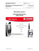
The HygroLab is available in 3 different models:
HygroLab 1: basic indicator
- Accepts up to 2 probes: ROTRONIC HygroClip digital probes or analog probes
1)
- Simultaneous display of relative humidity and temperature (one probe at a time)
- Software-based probe calibration (1-point or multi-point)
2)
1) ROTRONIC analog probes only – restrictions apply
2) Applies only to the ROTRONIC HygroClip digital probes
HygroLab 2: standard indicator
- Accepts up to 4 probes: ROTRONIC HygroClip digital probes or analog probes
1)
- Relative humidity, temperature, dew point, wet bulb, mixing ratio, enthalpy, etc., or user
defined calculation such as the difference between temperature and dew point
2)
- Software-based probe calibration (1-point or multi-point)
3)
- Possibility of using one of the four probes as a reference to do a 1-point adjustment of the
other probes
3)
- RS232 and RS485 serial ports or Ethernet (TCP/IP), RS-232 and RS-485 ports
4)
- Optional analog outputs (repeat analog probe input signals)
1) Third-party pressure probe or ROTRONIC analog probe – restrictions apply
2) Uses either a fixed barometric pressure value or the measurements from an analog pressure probe
for those parameters that require pressure as a computational input. The fixed pressure value can be
changed with the optional HW4 software.
3) Applies only to the ROTRONIC HygroClip digital probes
4) The optional HW4 software facilitates both networking and instrument configuration

IN-E-HyLab-V4_11
Rotronic AG
Bassersdorf, Switzerland
Document code Unit
Instruction Manual
Document Type
HygroLab bench top indicator version 4:
instruction manual
Document title
Page 4 of 51
© 2006; Rotronic AG IN-E-HyLab-V4_11
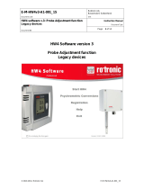
HygroLab 3: general purpose indicator with water activity functions
Same as HygroLab 2, except for:
- Accelerated water activity measurement with up to 4 probes (AwQuick mode): allows the
measurement of most products in typically 5 minutes
- Full equilibration measurement with up to 4 probes (Standard mode) with automatic
detection of equilibrium conditions
- Analog probe inputs with 12-bit resolution
HygroLab 1 HygroLab 2 and 3
2 General description
2.1 Power requirements
The HygroLab operates with an external AC adapter providing 9 to15 VDC, 100 mA. The power
receptacle is a 3.5 mm Jack female with DC+ center.
Note: when equipped with the optional Ethernet module, the HygroLab requires an AC adapter
able to provide 300 mA.
2.2 Probes and probe inputs
Model HygroLab 1 HygroLab 2 HygroLab 3
Number of probe inputs 2 4 4
Probe types
1)
ROTRONIC Digital
ROTRONIC Analog
ROTRONIC Digital
ROTRONIC Analog
Third Party Analog
ROTRONIC Digital
ROTRONIC Analog
Third Party Analog
Number of digital input channels 2 4 4
Number of analog input channels 4 8 8
Analog input A/D resolution 10-bit 10-bit 12-bit
1)
Unless otherwise specified when ordering, all probe inputs are factory programmed to accept a HygroClip
digital probe and the voltage powering the probe is the AC adapter voltage (12 VDC nominal). Prior to using
any analog probe, the corresponding probe input should be re-programmed. With the HygroLab 2 and 3, this
can be done with the HW4 software after connecting the RS232 port of the HygroLab to a PC (see separate
software manual).

IN-E-HyLab-V4_11
Rotronic AG
Bassersdorf, Switzerland
Document code Unit
Instruction Manual
Document Type
HygroLab bench top indicator version 4:
instruction manual
Document title
Page 5 of 51
© 2006; Rotronic AG IN-E-HyLab-V4_11
IMPORTANT: All probes connected to the HygroLab can be supplied with 5 VDC by opening solder pad B12
and closing solder pad B13 on the main PCB
. – see page 13: selection of the probe supply voltage.
2.2.1 HygroClip digital probes
The HygroLab is primarily designed for use with the ROTRONIC HygroClip digital humidity
temperature probes. These probes permit to take full advantage of all the features and functions of
the HygroLab.
The ROTRONIC HygroClip digital probes are highly accurate and are calibrated entirely by means
of software (no adjustment potentiometers). Because calibration and other data are stored in the
probe non-volatile memory, the probes are fully interchangeable. When a probe requires calibration
or has to be repaired, it can be replaced with another probe in a few seconds.
The ROTRONIC HygroClip digital probes are available in different configurations so as to meet the
requirements of each application:
HygroClip S
measurement in air
max. 85°C (185°F)
HygroClip SP05
measurement in air ducts
max. 85°C (185°F)
HygroClip HP28 insertion probe
measurement of materials in bulk
max. 85°C
(
185°F
)
HygroClip HK25 / HK40 air probe
measurement at high temperature
HK25: max. 100°C (212°F)
HK40: max. 200°C (392°F)
wire mesh filter
HygroClip SC05
measurement in tight spaces
max. 100°C (212°F)
HygroClip HS28 sword probe
measurement of paper stacks/rolls
max. 85°C
(
185°F
)
Note: all of the above probes are designed for use with the HygroPalm indicator and have a
DAT05 connector. An adapter cable MOK-01-B5 is required for connection to the HygroLab (see
Accessories). Similarly, the HygroClip probes designed for use with the HygroFlex transmitter

IN-E-HyLab-V4_11
Rotronic AG
Bassersdorf, Switzerland
Document code Unit
Instruction Manual
Document Type
HygroLab bench top indicator version 4:
instruction manual
Document title
Page 6 of 51
© 2006; Rotronic AG IN-E-HyLab-V4_11
have a T7 connector (not shown here). These probes can be connected to the HygroLab with the
T7-03-B5 adapter cable.
AW-DIO and AwVC-DIO water activity probes
Direct connection to the HygroLab
(probe has a B5 connector)
2.2.2 Analog probes
The HygroLab can be used with one or more analog probes. The corresponding probe input(s) as
well as
the scale and unit of the analog input signal(s) should be programmed with the HW4 software prior to
using the probe(s). For example, an analog pressure probe may used to provide the local value of
barometric pressure for the computation of parameters such as the wet bulb temperature, mixing
ratio or enthalpy.
Use of analog probes is subject to the following restrictions and limitations:
a. ROTRONIC analog humidity-temperature probes with the standard temperature output signal of
– 0.5…2.0 V = -50…200°C: because the HygroLab cannot read a negative voltage signal,
temperature measurement is generally limited to values above freezing.
b. Third-party analog probes: single channel probes (one signal), output signal within the range of
0 to 2.5 VDC, supply voltage: 9 VDC or less, maximum current consumption: 10 mA.
c. Resolution is limited by the 10-bit A/D converter
1)
used for the analog inputs. This converter
provides a theoretical maximum of 1024 counts for an input voltage span of 2.5 VDC. In theory,
this gives a resolution of 2.5 / 1024 = 0.00244 V. In practice, it is not possible to get 100% of the
counts from an A/D converter and the actual resolution should be about 0.0027 V (typical). For
example, if a probe with a temperature signal of 0…1 V = 0…100°C is being used, the signal
resolution will be about 100 x 1 x 0.0027 = 0.27°C.
1) HygroLab 3: 12-bit A/D converter
2.3 Analog outputs (optional)
Analog outputs are optional on the HygroLab 2 and 3. These outputs simply repeat the analog
inputs (if any analog probe is being used). See Connectors - Optional analog output connector.

IN-E-HyLab-V4_11
Rotronic AG
Bassersdorf, Switzerland
Document code Unit
Instruction Manual
Document Type
HygroLab bench top indicator version 4:
instruction manual
Document title
Page 7 of 51
© 2006; Rotronic AG IN-E-HyLab-V4_11
2.4 Serial interface (HygroLab 2 and 3)
Both the HygroLab 2 and 3 have external receptacles (located on the back panel) that provide both
a RS-232 and a RS-485 interface.
Serial interface settings
The HygroLab indicator is compatible with the ROTRONIC HW4 software (version 1.2.2 or higher)
and backward compatible with the ROTRONIC HW3 software. Each software uses a different
communications protocol and different settings regarding the parity, number of data bits and
number of stop bits. When interrogated, the HygroLab automatically recognizes which software and
which protocol is being used. This allows the HygroLab to be used with either HW3 or HW4 without
requiring a manual configuration of the HygroLab serial settings.
When used with HW4, the HygroLab automatically sets its serial interface as follows:
Parity : none
Data bits : 8
Stop bits : 1
When used with HW3, the HygroLab automatically sets its serial interface as follows:
Parity : even
Data bits : 7
Stop bits : 1
Note: the HygroLab will automatically set its serial interface to the above settings when interrogated
by a third-party software that uses the same ASCII commands as HW3 to request data. On models
with the optional Ethernet interface, the internal module must be re-configured as indicated in
document IN-E-TCPIP-Conf_11 (available in PDF format).
IMPORTANT: The HygroLab can be configured by the user with a Baud rate of 57600. The factory
default Baud rate of 19200 is compatible with both HW3 and HW4. The Baud rate of 57600 is
compatible only with HW4.
RS-232 interface
This interface is used to read measurement data, adjust any HygroClip probe connected to the
HygroLab and to configure the HygroFlex. The RS-232 allows direct connection of the HygroLab to
the COM port of a PC (up to 150 m / 490 ft separation)
The HW4 software (version 1.2.2 or higher) should be installed on the PC.
It is also possible to connect the HygroLab 2 or HygroLab 3 to an Ethernet network by using a
device server with a RS-232 port (TCP/IP encapsulation). Depending on the software used to
communicate with the HygroLab, the serial port of the device server should be configured as
indicated below:

IN-E-HyLab-V4_11
Rotronic AG
Bassersdorf, Switzerland
Document code Unit
Instruction Manual
Document Type
HygroLab bench top indicator version 4:
instruction manual
Document title
Page 8 of 51
© 2006; Rotronic AG IN-E-HyLab-V4_11
1) PC with HW4 (version 1.2.2 or higher):
Parity : none
Data bits : 8
Stop bits : 1
2) PC with a third-party software using the same ASCII commands as HW3 to request data (see
ASCII communications protocol).
Parity : even
Data bits : 7
Stop bits : 1
RS-485 interface
This interface is used to connect together a number of HygroLab indicators (as well as other
ROTRONIC devices) so as to form a RS-485 multi-drop. This is useful when the number of PC
ports is limited and provides savings on cabling costs. The RS-485 interface has the same
functionality as the RS-232 interface (measurement data, adjustment of HygroClip probes and
device configuration).
In a RS-485 multi-drop, the master is automatically the device that is connected to a COM port,
USB port or network port (Ethernet) of the PC. Any ROTRONIC device that is equipped with both a
RS-232, USB or Ethernet interface and a RS-485 interface can be used as the master. The other
devices in the RS-485 multi-drop are slaves. Any HygroLab 2 or HygroLab 3 indicator can be used
either as a slave or a master, without special configuration other than giving a unique RS-485
address to each device and setting each device to use the same Baud rate.

IN-E-HyLab-V4_11
Rotronic AG
Bassersdorf, Switzerland
Document code Unit
Instruction Manual
Document Type
HygroLab bench top indicator version 4:
instruction manual
Document title
Page 9 of 51
© 2006; Rotronic AG IN-E-HyLab-V4_11
Example of a RS-485 multi-drop
In the following example, the master (address 1) is directly connected to a COM port of the PC
(RS-232). Units 2 to 64 are slaves.
Address 64 Address 2 Address 1
RS232: 3 wires
(incl. ground)
max. 150 m
Address 3
RS485: 2 wires, up to 1000m
Important:
- All devices connected to the same RS-485 multi-drop should use the same baud rate
- Each device within the same RS-485 multi-drop should have a unique address
- In theory, HW4 allows an unlimited number of masters, each with up to 63 slaves. Practical limits
to the total number of devices are set by the PC.
PC with HW4: Except for the distance limitations specific of a RS-232 connection, the above
diagram applies also when the master (for example HygroClip DI interface) is connected to a USB
port or to an Ethernet network.
2.5 Optional Ethernet (TCP/IP) interface (HygroLab 2 and 3)
As an option, both the HygroLab 2 and HygroLab 3 can be ordered with an Ethernet (TCP/IP)
interface in addition to the standard RS-232 and RS-485 serial interface. All different types of
interface offer the same functionality. The HW4 software accepts connection to the PC by means of
an Ethernet network.

IN-E-HyLab-V4_11
Rotronic AG
Bassersdorf, Switzerland
Document code Unit
Instruction Manual
Document Type
HygroLab bench top indicator version 4:
instruction manual
Document title
Page 10 of 51
© 2006; Rotronic AG IN-E-HyLab-V4_11
3 Optional configuration and communication software
Depending on the model of HygroLab, the ROTRONIC HW4 software (version 1.2.2 or higher)
offers additional functionality such as:
- Networking (unlimited number of masters, up to 64 units per multi-drop)
- Instrument configuration (unit system, etc.)
- Adjustment of the ROTRONIC HygroClip digital probes
- Data logging to a PC disk file
- Graphic functions (both on and off-line)
- Alarm functions (on-screen display, reports, notification by e-mail, etc.)
HW4 is compatible with Windows XP, NT4 with SP6a or higher. For more details see separate
instruction manual provided with the software.
The HygroLab is backward compatible with the ROTRONIC HW3 software (Windows 98 or NT)
4 How to configure the HygroLab
The HygroLab is configured by the factory as specified when the instrument was ordered. The
configuration can be modified by the user and this requires connecting the HygroLab to a PC with
the ROTRONIC HW4 software installed (version 1.2.2 or higher).
Depending on the model of HygroLab, the following can be configured by the user with Device
Manager in HW4 (where relevant, the factory default is indicated in bold):
- Device name
- RS-485 address [0]
- Device write protection with password [disabled]
- Fixed barometric pressure value used in some psychrometric calculations [1013.25 hPa]
- Dew or frost point calculation below freezing [frost point]
- Language and unit system
- Probe input type (HygroClip probe, analog pressure probe, other analog probe)
- Input name
- Calculated parameter (HygroClip probe only)
- Barometric pressure (fixed value or read from an input) [fixed]
- Alarm threshold (low and high) for humidity, temperature, calculated parameter or other.
- Parameter or custom calculation associated with each analog output and output scale
- Custom calculation (example: difference between two parameters such as dew point)
- Optional display configuration (resolution, trend indicators, parameters to be displayed)
- Keypad: restricted menu access [not restricted]
- Baud rate (serial interface) [19200]
For more details see separate instruction manual provided with the software.
4.1 Internal service connector (HygroLab configuration)
All HygroLab models have an internal RS-232 service connector (MTA) located on the main PCB
(see PCB connections). Cable AC1623 is required to connect the HygroFlex MTA connector to
COM port of a PC.

IN-E-HyLab-V4_11
Rotronic AG
Bassersdorf, Switzerland
Document code Unit
Instruction Manual
Document Type
HygroLab bench top indicator version 4:
instruction manual
Document title
Page 11 of 51
© 2006; Rotronic AG IN-E-HyLab-V4_11
Use of the MTA service connector is limited to configuring the instrument (unit system, output
range, display, etc.). Both the HygroLab 2 and HygroLab 3 can also be configured via one of the
external digital ports.
Instrument configuration requires a PC with the HW4 software installed. Instructions for configuring
the HygroLab are provided in the software manual.
4.2 Baud rate compatibility requirements
Depending on the model, devices from ROTRONIC use one of the following Baud rates as the
factory default:
• 57600 bps: HygroLog NT data logger and docking stations
• 19200 bps: HygroPalm and HygroLab indicators, HygroFlex and M33 transmitters, HygroClip
Alarm programmable alarm card, HygroClip DI interface, HygroStat MB Thermo-Hygrostat
The factory default Baud rate of the HygroLab is compatible both with both the ROTRONIC HW4
and HW3 software and is the recommended Baud rate for the HygroLab.
IMPORTANT:
• All devices connected to a RS-485 multi-drop network (master and slaves) must use the
same Baud rate
• Models with the optional Ethernet (TCP/IP) interface: after using HW4 – Device Manager to
change the Baud rate, you should also change the configuration of the internal Ethernet
module to the new Baud rate (see separate HW4 manual).
Devices and internal Ethernet modules with mismatched Baud rate will not communicate together.
• The Baud rate configuration of a ROTRONIC device can be changed with the Device
Manager function (Digital Interface tab) available from within the HW4 software.
• The Baud rate of a Digi Module can be changed only from the module web interface. See
separate document IN-E-TCPIP-Conf_11 (available in PDF format).
4.3 Ethernet local area network
ROTRONIC devices with an Ethernet (TCP/IP) interface presently use an internal module
manufactured by Digi International (Digi Connect ME for a wired connection, Digi Connect WI-ME
for a wireless connection). Both types of module feature a web interface that is used to configure
the module.
IMPORTANT: The TCP/IP settings of models with an Ethernet (TCP/IP) interface should be
configured to be compatible with the local area network. Detailed instructions are provided
separately in document IN-E-TCPIP-Conf_11 (available in PDF format).
Models with an Ethernet (TCP/IP) interface are shipped with a Device Configuration Certificate that
provides information about the factory configuration settings of both the Ethernet module and
device. See example below:

IN-E-HyLab-V4_11
Rotronic AG
Bassersdorf, Switzerland
Document code Unit
Instruction Manual
Document Type
HygroLab bench top indicator version 4:
instruction manual
Document title
Page 12 of 51
© 2006; Rotronic AG IN-E-HyLab-V4_11
Setting Value
DHCP or Static Address Static
IP Address 192.168.1.1
Subnet Mask 255.255.255.0
Default Gateway 192.168.1.0
TCP Port 2101
MAC Address 00:40:9D:28:2D:2A
Firmware Release (device) 1.4
User Name (web interface) rotronic
Password (web interface) wlan
Serial Port Configuration Profile TCP Sockets
Basic Serial Settings
Baud Rate 57600
Data Bits 8
Parity None
Stop Bits 1
Flow Control None
4.4 RS-485 multi-drop network (HygroLab 2 and 3)
Both the HygroLab 2 and HygroLab 3 feature a RS-485 connector. When the number of available
PC ports is limited, this connector can be used to connect together up to 64 HygroLab (or other
devices) in a multi-dropped arrangement. In principle, an unlimited number of such networks can
be monitored with the HW4 software, but each RS-485 multi-drop network is limited to 64 devices.
The HygroLab can be used either as a slave or a master, without special configuration. The master
is automatically the device that is directly connected to the PC or LAN by means of a RS-232 port
or TCP/IP port.
RS-485 Address: the RS-485 address is used to identify the individual devices that are connected
to a RS-485 multi-drop and must be unique to each device. This address is part of the HygroLab
communications protocol. The factory default for the RS-485 address is 00. In general, this address
should not be changed manually (see note below). As far as HW4 is concerned, all masters can
share the same RS-485 address. When the HW4 command “Search for RS-485 slaves” is being
used, HW4 automatically changes from 00 to 01 the RS-485 address of any master that has slaves
attached. As a result, all masters end up with the same RS-485 network address (01). In addition,
HW4 automatically changes the RS-485 address of the slaves in each multi-drop from 00 (factory
default) to a unique address ranging from 02 to 64. The same address range (02 to 64) is used
again when there is more than one multi-drop RS485 network.
Notes:
- We recommend using HW4 to give each HygroLab a unique name for easier identification.
- In the situation where an RS-485 network is to be monitored by software other than HW4, you
will have to use HW4 to give each device a unique RS-485 address prior to connecting to the
network.
- If you change an instrument from master to slave, be sure to change the RS address of the
instrument to 00 before establishing the RS-485 connection. Not doing so may prevent HW4
from detecting the instrument. After detecting the instrument, HW4 will automatically change
the RS address to 02 or higher. Please note that HW4 may eventually change the address of
any master with address 00.

IN-E-HyLab-V4_11
Rotronic AG
Bassersdorf, Switzerland
Document code Unit
Instruction Manual
Document Type
HygroLab bench top indicator version 4:
instruction manual
Document title
Page 13 of 51
© 2006; Rotronic AG IN-E-HyLab-V4_11
- All devices within a multi-drop should use the same Baud rate. See Baud rate compatibility
requirements.
- Models with Ethernet (TCP/IP) interface: please note that the Baud rate of the HygroLab and
the Baud rate of the internal Ethernet module should be set to the same value.
RS-485 Cable: Using a symmetrical transmission method in combination with low capacity/ low
attenuation twisted pair cables, allows extremely reliable long distance connections. The use of a
high grade shielded cable avoids cross talk between the transmitted signals and also reduces the
potential of external interference. For the RS-485 cable, we recommend using a cable
Cat. 5e ANSI/ TIA /EIA-568-A-5.
In general the RS-485 cable should be shielded and comply with the following specifications:
- Cable capacitance <=300pF/m or 90 pF/ft
- Line impedance 100 Ω ±15 Ω
- Line resistance 140 Ω/km or 225 Ω
- Signal lines Twisted pair
In addition, we recommend terminating each end of the RS-485 cable with a 240 Ohm resistor.
RS485 Network:
Addr. 1 Addr. n
RS485 device connectors
240 Ω
240 Ω
Note: all instruments connected to the network should use the same baud rate
Voltage potential issues: The existence of a voltage-potential between instruments that are
interconnected can be a source on concern in large installations, installations with different mains
power supply and in inter-building networking.
As a first measure, the shield of a signal cable should be connected at both ends. In the case of a
data cable, a low-resistance potential equalization cable may also have to be used. This cable
should be run parallel and as near as possible to the data cable, preferably in the same conduit.
The shield of the data cable should under no circumstances be used as equalization cable! The
conductors of the potential equalization cable should ideally be stranded in order to be effective
also in case of high- frequency interference.

IN-E-HyLab-V4_11
Rotronic AG
Bassersdorf, Switzerland
Document code Unit
Instruction Manual
Document Type
HygroLab bench top indicator version 4:
instruction manual
Document title
Page 14 of 51
© 2006; Rotronic AG IN-E-HyLab-V4_11
The following points should also be observed:
• Close the parasitic circuit
• Connect all devices to the potential equalizing cable as often as possible. Electrical
conductors such as machine elements, metal tubes or supporting constructions should be
integrated into the system.
• Protect the potential-equalization cable and connections against corrosion.
• Select the cross-section of the potential equalization cable according to the maximum
equalization current.
If these different measures do not correct the problem, a galvanic separation according to
ISO 9549 may have to be installed. You may also want to consider the use of fiber-optic cables.
4.5 Selection of the probe supply voltage (main PCB)
Starting with PCB number 66.0739.0302, the probes can be powered with either 5 VDV or directly
from the AC adapter (nominal 12 VDC). The default factory setting is to use the voltage from the
AC adapter. All probes connected to the HygroLab can be supplied with 5 VDC by opening solder
pad B12 and closing solder pad B13 on the main PCB. Depending on the probe model, changing
the probe supply voltage may require the probe to be re-adjusted (please, consult factory).
5 Operation
Connect the AC adapter to the Power connector of the HygroLab and connect a probe
1).
Press on
the ON/OFF key. After a brief test and introductory message, the measurements appear on the LC
display. Measurements are updated to the display at the rate of 0.75 sec. x number of digital
probes (HygroClip) connected to the HygroLab.
1) Unless otherwise specified when ordering, all probe inputs are factory programmed to accept a HygroClip
digital probe. Prior to using any analog probe, the corresponding probe input should be re-programmed. This
can be done with the HW4 software after connecting the RS232 port of the HygroLab to a PC (see separate
HW4 manual).

IN-E-HyLab-V4_11
Rotronic AG
Bassersdorf, Switzerland
Document code Unit
Instruction Manual
Document Type
HygroLab bench top indicator version 4:
instruction manual
Document title
Page 15 of 51
© 2006; Rotronic AG IN-E-HyLab-V4_11
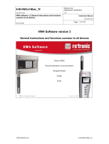
HygroLab 1 HygroLab 2 and 3
5.1 Unit system
The unit system can easily be set to Metric or English from the keypad (except HygroLab 1) -see
MENU, SETTINGS. The unit system can also be changed from a PC with the optional HW4
software installed. In that case, connect the HygroLab to a free COM port of the PC using either the
internal service connector (all models) or the RS232 port (HygroLab 2 and 3)
Note: except for the HygroLab 1, the instrument can be configured to display water activity instead
of relative humidity: (instrument configuration with the HW4 software):
1.000 Aw = 100.0 %RH
To change the factory configuration for humidity either use the keypad MENU, SETTINGS (except
HygroLab 1) or use the optional HW4 software installed on a PC and the appropriate connecting
cable: cable AC1623 for all models (see Accessories) or cable type RS232 9pol ST-BU for the
HygroLab 2 and HygroLab 3 (see Connectors for part number).
5.2 Display and keypad
The LC display shows which probe input is being displayed (small indicator on top of the display)
and up to 2 parameters measured by the probe, with the associated engineering unit. When
relevant, the message line provides additional information.
Parameter or
Trend indicator
Message Line
Engineering
Units
Probe Input
(1-4) from left to right
Humidity and Temperature
Calculated Value and Temperature
Calculated Value and Humidity

IN-E-HyLab-V4_11
Rotronic AG
Bassersdorf, Switzerland
Document code Unit
Instruction Manual
Document Type
HygroLab bench top indicator version 4:
instruction manual
Document title
Page 16 of 51
© 2006; Rotronic AG IN-E-HyLab-V4_11
ENTER: when the menu is
active, press this key to confirm
a selection
UP / DOWN: press one of these
keys to change the probe input
that is being displayed. When the
menu is active, use these keys to
navigate the menu, make a
selection or to change a number
ON/OFF: turns the
instrument on or off
MENU : press this key
to activate the functions
menu. The different
menu items appear on
the LCD message line.
Press this key again to
exit the menu
5.3 Probe Input Selection
The display can be switched between probes with the ▼ or ▲ key. The selection is confirmed on
the message line of LC display as well as by an indicator located at the top of the display.
6 Function menu
To access the function menu, press the MENU key. The first menu item appears on the message
line of the LC display. Use the ▼ or ▲ key to navigate the menu. When the desired menu item
appears on the message line of the LC display, press the ENTER key to select. Some menu items
have sub-items. These can be selected with the ▲ or ▼ and ENTER keys. To exit the menu and
return to the normal display mode, press the MENU key. The instrument also returns automatically
to the normal display mode when no key is being pressed for some time (main menu: 10 sec.,
submenu: 30 sec.).

IN-E-HyLab-V4_11
Rotronic AG
Bassersdorf, Switzerland
Document code Unit
Instruction Manual
Document Type
HygroLab bench top indicator version 4:
instruction manual
Document title
Page 17 of 51
© 2006; Rotronic AG IN-E-HyLab-V4_11
6.1 CALCULATE (HygroLab 2 and 3)
Definition
This function is used to select or view the humidity parameter that is calculated by the instrument.
The calculated parameter is selected individually for each probe connected to the instrument
1)
.
Prior to entering this function, select on the display the probe to program.
1) Does not apply to third-party analog probes.
The unit system (Metric or English) can be changed with the keypad (see Functions, Settings) or
with the optional HW4 software, when the HygroLab is connected to a PC.
Selections
Parameter Metric English Lab 1 Lab 2 Lab 3
Dew Point / Frost Point
1)
°C °F
N/A
x x
Wet Bulb Temperature
2)
°C °F
N/A
x x
Enthalpy
2)
J/g BTU/lb N/A
X X
Vapor Concentration g/m
3
gr/cuft N/A
X X
Specific Humidity
2)
g/kg gr/lb N/A
X X
Mixing Ratio
2)
g/kg gr/lb N/A
X X
Vapor Concentration
at Saturation
g/m
3
gr/cuft N/A
X X
Partial Pressure
of Water Vapor
hPa PSI or In Hg N/A
X X
Saturation Pressure
of Water Vapor
hPa PSI or In Hg N/A
X X
1) The standard factory setting is frost point for values below freezing. This setting can be changed to dew
point with the optional HW4 software
2)
Calculation of this parameter requires barometric pressure as an input. The fixed value used for barometric
pressure can be changed either directly from the keypad - see MENU, SETTINGS - or with the optional HW4
software (all models). The HygroLab 2 or 3 can also be configured to accept the input from an analog
pressure probe (variable pressure value).

IN-E-HyLab-V4_11
Rotronic AG
Bassersdorf, Switzerland
Document code Unit
Instruction Manual
Document Type
HygroLab bench top indicator version 4:
instruction manual
Document title
Page 18 of 51
© 2006; Rotronic AG IN-E-HyLab-V4_11
6.2 MODE (HygroLab 3)
Definition
This function is used to set the operating mode of the HygroLab 3
Selections
Standard : normal operating mode (relative humidity, temperature, dew point, etc.)
Q AwQuick : water activity measurement with the AwQuick algorithm for measurements in
typically 5 minutes.
E AwE : conventional water activity measurement with automatic detection of equilibrium
conditions.
Note:
The operating mode selection applies to all probe inputs. Upon start up, the HygroLab 3
remembers in which mode it was before being turned off
● Standard Mode:
This mode is the default mode of the HygroLab 3. Upon powering the HygroLab 3, the instrument
automatically defaults to the standard mode.
In the standard mode, the HygroLab 3 displays the humidity and temperature measured by the
selected probe. Trend indicators appear one minute after powering up the instrument (▲ or ▼
arrow to the left of the water activity and temperature values). These indicators are used to detect
equilibrium conditions as required for example during probe calibration. The probe is at equilibrium
when both the up and down arrow are displayed at the same time.
● AwE mode:
This mode is essentially the same as the standard mode with the difference that the HygroLab 3
automatically detects equilibrium conditions and ends the measurement at that time by freezing the
display.
● AwQuick mode:
This mode accelerates the measurement of water activity and provides a result in typically 5
minutes. When temperature conditions are stable (both at the product and probe), the
measurement obtained with the AwQuick mode is generally within ± 0.005 aw of the measurement
that would be obtained by waiting for full equilibration of the product and probe.
Depending on the mode that was selected, proceed as follows

IN-E-HyLab-V4_11
Rotronic AG
Bassersdorf, Switzerland
Document code Unit
Instruction Manual
Document Type
HygroLab bench top indicator version 4:
instruction manual
Document title
Page 19 of 51
© 2006; Rotronic AG IN-E-HyLab-V4_11
a) Standard Mode:
No further action is required after selecting this mode. Simply proceed with the measurements.
b) AwE Mode:
Upon selecting this mode, the HygroLab 3 displays the following:
0. 0 0 0
1
E H S [ A w / m i n ]
Use the ▼ or ▲ arrow to set the definition of stable humidity. In the above example, the HygroLab
will consider humidity to be at equilibrium when the rate of change of the humidity signal is less
than 0.0001 Aw per minute. Default value: 0.0001 Aw / min
Press the ENTER key to record and confirm this setting. The display now shows the following:
0. 0 1
E T S [
°
C/min]
Use the UP or DOWN arrow to set the definition of stable temperature. In the above example, the
HygroLab will consider temperature to be at equilibrium when the rate of change of the temperature
signal is less than 0.01 °C per minute. Default value: 0.01 °C / min
Press the ENTER key to record and confirm this setting. The AwE mode is now active.
When ready to measure, press the ENTER key to access and start the AwE mode. Press the
ENTER key again to stop the AwE mode at any time and return to the Standard mode.
Notes:
When the HygroLab 3 is in the AwE mode, pressing the ENTER key automatically starts the
AwE mode, unless the MENU key was pressed immediately before pressing the ENTER key.
The ON / OFF key is inoperative in the AwE mode. You must stop the AwE mode in order to be
able to turn the power of with the red ON/OFF key.
For instructions on using the AwE mode, see Water Activity Measurement.

IN-E-HyLab-V4_11
Rotronic AG
Bassersdorf, Switzerland
Document code Unit
Instruction Manual
Document Type
HygroLab bench top indicator version 4:
instruction manual
Document title
Page 20 of 51
© 2006; Rotronic AG IN-E-HyLab-V4_11
c) AwQuick Mode:
Upon selecting this mode, the HygroLab 3 displays the following:
4
Q D w e l l [ m i n ]
Use the ▼ or ▲ arrow to set the dwell time. In the above example, the HygroLab 3 will wait 4
minutes before processing the humidity data with the AwQuick algorithm.
Default value: 4 min (recommended value)
Press the ENTER key to record and confirm this setting. The display now shows the following:
0. 0 1
Q T S [
°
C/min]
Use the UP or DOWN arrow to set the definition of stable temperature. In the above example, the
HygroLab will consider temperature to be stable when the rate of change of the temperature signal
is less than 0.01 °C per minute.
Default value: 0.01 °C / min
Press the ENTER key to record and confirm this setting. The AwQuick mode is now active.
When ready to measure, press the ENTER key to access and start the AwQuick mode. Press the
ENTER key again to stop the AwQuick mode at any time and return to the Standard mode.
Notes:
When the HygroLab 3 is in the AwQuick mode, pressing the ENTER key automatically starts
the AwQuick mode, unless the MENU key was pressed immediately before pressing the
ENTER key.
The ON / OFF key is inoperative in the AwQuick mode. You must stop the AwQuick mode in
order to be able to turn the power of with the red ON/OFF key.
For instructions on using the AwQuick mode, see Water Activity Measurement.
/