
INSTRUCTION MANUAL
GUIDE D'UTILISATION
MANUAL DE INSTRUCCIONES
DW367, DW368, DW369
7-1/4" (184 mm) Circular Saws
Scies circulaires de 184 mm (7-1/2 po)
Sierras circular de 184 mm (7-1/4")
INSTRUCTIVO DE OPERACIÓN, CENTROS DE SERVICIO Y PÓLIZA
DE GARANTÍA. ADVERTENCIA: LÉASE ESTE INSTRUCTIVO ANTES
DE USAR EL PRODUCTO.
If you have questions or comments, contact us.
Pour toute question ou tout commentaire, nous contacter.
Si tiene dudas o comentarios, contáctenos.
1-800-4-DEWALT • www.dewalt.com
Page is loading ...

1
English
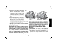
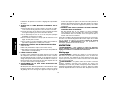
Defi nitions: Safety Guidelines
The definitions below describe the level of severity for each
signal word. Please read the manual and pay attention to
these symbols.
DANGER: Indicates an imminently hazardous situation
which, if not avoided, will result in death or serious
injury.
WARNING: Indicates a potentially hazardous situation
which, if not avoided, could result in death or serious
injury.
CAUTION: Indicates a potentially hazardous situation
which, if not avoided, may result in minor or moderate
injury.
NOTICE: indicates a practice not related to personal
injury which, if not avoided, may result in property
damage.
IF YOU HAVE ANY QUESTIONS OR COMMENTS ABOUT THIS OR
ANY D
EWALT TOOL, CALL US TOLL FREE AT: 1-800-4-DEWALT
(1-800-433-9258).
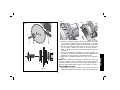
GENERAL SAFETY INSTRUCTIONS
WARNING! Read and understand all instructions.
Failure to follow all instructions listed below may result
in electric shock, fire and/or serious personal injury.
SAVE THESE INSTRUCTIONS
WORK AREA
• Keep your work area clean and well lit. Cluttered benches and
dark areas invite accidents.
• Do not operate power tools in explosive atmospheres, such
as in the presence of flammable liquids, gases, or dust.
Power tools create sparks which may ignite the dust or fumes.
• Keep bystanders, children, and visitors away while operating
a power tool. Distractions can cause you to lose control.
ELECTRICAL SAFETY
• Grounded tools must be plugged into an outlet properly
installed and grounded in accordance with all codes and
ordinances. Never remove the grounding prong or modify
the plug in any way. Do not use any adapter plugs. Check
with a qualified electrician if you are in doubt as to whether
the outlet is properly grounded. If the tools should electrically
malfunction or break down, grounding provides a low resistance
path to carry electricity away from the user. Applicable only to
Class I (grounded) tools.
• Double insulated tools are equipped with a polarized plug
(one blade is wider than the other.) This plug will fit in a
polarized outlet only one way. If the plug does not fit fully
in the outlet, reverse the plug. If it still does not fit, contact
a qualified electrician to install a polarized outlet. Do not
change the plug in any way. Double insulation
eliminates
the need for the three wire grounded power cord and grounded
power supply system. Applicable only to Class II (double
insulated) tools. The DW367, DW368 and DW369 are double
insulated tools.
• Avoid body contact with grounded surfaces such as pipes,
radiators, ranges and refrigerators. There is an increased risk
of electric shock if your body is grounded.
• Don’t expose power tools to rain or wet conditions. Water
entering a power tool will increase the risk of electric shock.
• Do not abuse the cord. Never use the cord to carry the
tools or pull the plug from an outlet. Keep cord away from

2
English
heat, oil, sharp edges or moving parts. Replace damaged
cords immediately. Damaged cords increase the risk of electric
shock.
• When operating a power tool outside, use an outdoor
extension cord marked “W-A” or “W.” These cords are rated
for outdoor use and reduce the risk of electric shock. When using
an extension cord, be sure to use one heavy enough to carry the
current your product will draw. An undersized cord will cause a
drop in line voltage resulting in loss of power and overheating.
The following table shows the correct size to use depending on
cord length and nameplate ampere rating. If in doubt, use the
next heavier gauge. The smaller the gauge number, the heavier
the cord.
Minimum Gauge for Cord Sets
Volts Total Length of Cord in Feet
120V 0-25 26-50 51-100 101-150
240V 0-50 51-100 101-200 201-300
Ampere Rating
More Not more AWG
Than Than
12 - 16 14 12 Not Recommended
PERSONAL SAFETY
• Stay alert, watch what you are doing and use common
sense when operating a power tool. Do not use tool while
tired or under the influence of drugs, alcohol, or medication.
A moment of inattention while operating power tools may result
in serious personal injury,
• Dress properly. Do not wear loose clothing or jewelry.
Contain long hair. Keep your hair, clothing, and gloves away
from moving parts. Loose clothes, jewelry, or long hair can be
caught in moving parts. Air vents often cover moving parts and
should also be avoided.
• Avoid accidental starting. Be sure switch is off before
plugging in. Carrying tools with your finger on the switch or
plugging in tools that have the switch on invites accidents.
• Remove adjusting keys or wrenches before turning the tool
on. A wrench or a key that is left attached to a rotating part of
the tool may result in personal injury.
• Do not overreach. Keep proper footing and balance at all
times. Proper footing and balance enables better control of the
tool in unexpected situations.
• Use safety equipment. Always wear eye protection. Dust
mask, non-skid safety shoes, hard hat, or hearing protection
must be used for appropriate conditions.
TOOL USE AND CARE
• Use clamps or other practical way to secure and support the
workpiece to a stable platform. Holding the work by hand or
against your body is unstable and may lead to loss of control.
• Do not force tool. Use the correct tool for your application.
The correct tool will do the job better and safer at the rate for
which it is designed.
• Do not use tool if switch does not turn it on or off. Any tool
that cannot be controlled with the switch is dangerous and must
be repaired.
• Disconnect the plug from the power source before making
any adjustments, changing accessories, or storing the tool.
Such preventative safety measures reduce the risk of starting
the tool accidentally.
• Store idle tools out of reach of children and other untrained
persons. Tools are dangerous in the hands of untrained users.
• Maintain tools with care. Keep cutting tools sharp and
clean. Properly maintained tools, with sharp cutting edges are
less likely to bind and are easier to control.

3
English
• Check for misalignment or binding of moving parts, breakage
of parts, and any other condition that may affect the tools
operation. If damaged, have the tool serviced before using.
Many accidents are caused by poorly maintained tools.
• Use only accessories that are recommended by the
manufacturer for your model. Accessories that may be
suitable for one tool, may become hazardous when used on
another tool.
SERVICE
• Tool service must be performed only by qualified repair
personnel. Service or maintenance performed by unqualified
personnel could result in a risk of injury.
• When servicing a tool, use only identical replacement
parts. Follow instructions in the maintenance section of
this manual. Use of unauthorized parts or failure to follow
maintenance instructions may create a risk of electric shock or
injury.
Additional Safety Instructions for
Circular Saws
DANGER! Keep hands away from cutting area and blade.
Keep your second hand on auxiliary handle, or motor housing.
If both hands are holding the saw, they cannot be cut by the
blade.
WARNING: Blades coast after turn off.
• Keep your body positioned to either side of the blade, but
not in line with the saw blade. KICKBACK could cause the
saw to jump backwards (see Causes and Operator Prevention of
Kickback and KICKBACK).
• Do not reach underneath the work. The guard can not protect
you from the blade below the work.
• Check lower guard for proper closing before each use. Do
not operate saw if lower guard does not move freely and
close instantly. Never clamp or tie the lower guard into the
open position. If saw is accidentally dropped, the lower guard
may be bent. Raise the lower guard with the retracting handle and
make sure it moves freely and does not touch the blade or any
other part, at all angles and depth of cut.
• Check the operation and condition of the lower guard spring.
If the guard and the spring are not operating properly, they
must be serviced before use. Lower guard may operate
sluggishly due to damaged parts, gummy deposits, or a buildup
of debris.
• Lower guard should be retracted manually only for special
cuts such as “pocket cuts” and “compound cuts.” Raise
lower guard by retracting handle. As soon as blade enters the
material, lower guard must be released. For all other sawing,
the lower guard should be allowed to operate automatically.
• Always observe that the lower guard is covering the blade
before placing saw down on bench or floor. An unprotected,
coasting blade will cause the saw to walk backwards, cutting
whatever is in its path. Be aware of the time it takes for the blade
to stop after switch is released.
• NEVER hold piece being cut in your hands or across your
leg. It is important to support the work properly to minimize body
exposure, blade binding, or loss of control.
• Hold tool by insulated gripping surfaces when performing
an operation where the cutting tool may contact hidden
wiring or its own cord. Contact with a “live” wire will also make
exposed metal parts of the tool “live” and shock the operator.
• When ripping, always use a rip fence or straight edge guide.
This improves the accuracy of cut and reduces the chance for
blade binding.

4
English
• When blade is binding, or when interrupting a cut for any
reason, release the trigger and hold the saw motionless
in the material until the blade comes to a complete stop.
Never attempt to remove the saw from the work or pull the
saw backward while the blade is in motion or kickback may
occur. Investigate and take corrective actions to eliminate the
cause of blade binding.
• When restarting a saw in the workpiece, center the saw blade
in the kerf and check that the saw teeth are not engaged into
the material. If saw blade is binding, it may walk up or kickback
from the workpiece as the saw is restarted.
• Support large panels to minimize the risk of blade pinching
and kickback. Large panels tend to sag under their own weight.
Support must be placed under the panel on both sides, near the
line of cut and near the edge of the panel.
• Do not use dull or damaged blade. Unsharpened or improperly
set blades produce narrow kerf causing excessive friction, blade
binding, and kickback.
• Blade depth and bevel adjusting locking levers must be tight
and secure before making cut. If blade adjustment shifts while
cutting, it may cause binding and KICKBACK.
• Use extra caution when making a “Pocket Cut” into existing
walls or other blind areas. The protruding blade may cut objects
that can cause kickback.
WARNING: Some dust created by power sanding, sawing,
grinding, drilling, and other construction activities contains chemicals
known to cause cancer, birth defects or other reproductive harm.
Some examples of these chemicals are:
• lead from lead-based paints,
• crystalline silica from bricks and cement and other masonry
products, and
• arsenic and chromium from chemically-treated lumber
(CCA).
• Always use blades with correct size and shape (diamond
vs. round) arbor holes. Blades that do not match the mounting
hardware of the saw will run eccentrically, causing loss of
control.
• Never use damaged or incorrect blade washers or bolts. The
blade washers and bolt were specially designed for your saw, for
optimum performance and safety of operation.
• Avoid cutting nails. Inspect for and remove all nails from lumber
before cutting.
• Do not operate this tool for long periods of time. Vibration
caused by the operating action of this tool may cause permanent
injury to fingers, hands, and arms. Use gloves to provide extra
cushion, take frequent rest periods, and limit daily time of use.
CAUSES AND OPERATOR PREVENTION OF KICKBACK
• Kickback is a sudden reaction to a pinched, bound or misaligned
saw blade, causing an uncontrolled saw to lift up and out of the
workpiece toward the operator.
• When the blade is pinched or bound tightly by the kerf closing
down, the blade stalls and the motor reaction drives the unit
rapidly back toward the operator.
• If the blade becomes twisted or misaligned in the cut, the teeth
at the back edge of the blade can dig into the top surface of the
wood causing the blade to climb out of the kerf and jump back
toward operator.
• Kickback is the result of tool misuse and/or incorrect operating
procedures or conditions and can be avoided by taking proper
precautions as given below:
• Maintain a firm grip with both hands on the saw and position
your body and arm to allow you to resist kickback forces.
Kickback forces can be controlled by the operator, if proper
precautions are taken.

5
English
Your risk from these exposures varies, depending on how often you
do this type of work. To reduce your exposure to these chemicals:
work in a well ventilated area, and work with approved safety
equipment, such as those dust masks that are specially designed to
filter out microscopic particles.
• Avoid prolonged contact with dust from power sanding,
sawing, grinding, drilling, and other construction activities.
Wear protective clothing and wash exposed areas with soap
and water. Allowing dust to get into your mouth, eyes, or lay on
the skin may promote absorption of harmful chemicals.
WARNING: Use of this tool can generate and/or disburse dust,
which may cause serious and permanent respiratory or other injury.
Always use NIOSH/OSHA approved respiratory protection
appropriate for the dust exposure. Direct particles away from face
and body.
WARNING: ALWAYS USE SAFETY GLASSES. Everyday
eyeglasses are NOT safety glasses. Also use face or dust mask if
cutting operation is dusty. ALWAYS WEAR CERTIFIED SAFETY
EQUIPMENT:
• ANSI Z87.1 eye protection (CAN/CSA Z94.3),
• ANSI S12.6 (S3.19) hearing protection,
• NIOSH/OSHA repiratory protection.
WARNING: When cutting into walls, floors or wherever live
electrical wires may be encountered, DO NOT TOUCH ANY METAL
PARTS OF THE TOOL! Hold the tool only by insulated grasping
surfaces to prevent electric shock if you cut into a live wire.
• The label on your tool may include the following symbols. The
symbols and their definitions are as follows:
V ............volts A .........amperes
Hz ..........hertz W ........watts
min ........minutes
......alternating current
.....direct current ......alternating or direct
..........Class I Construction ...........current
..............(grounded)
n
o .......no load speed
..........Class II Construction ........earthing terminal
..............(double insulated) .......safety alert symbol
…/min ...per minute
BPM ...beats per minute
RPM ......revolutions per minute
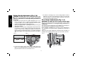
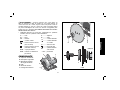
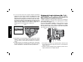
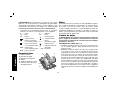
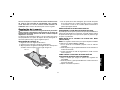
FEATURES
C
A
D
F
B
E
A. End cap
B. Trigger switch
C. Bevel angle adjustment
D. Shoe
E. Blade clamping screw
F. Lower blade guard
Motor
Your DEWALT tool is powered
by a D
EWALT motor. Be sure
your power supply agrees with
nameplate marking. As little as 10% lower voltage can cause loss of
power and can result in overheating. All D
EWALT tools are factory-
tested; if this tool does not operate, check the power supply.
Changing Blades
WARNING: To reduce the risk of serious personal injury,
turn tool off and disconnect tool from power source before
making any adjustments or removing/installing attachments or
accessories.

6
English
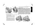
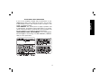
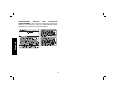
TO INSTALL THE BLADE (FIG. 1–4)
1. Place inner clamp washer (G) on saw spindle with the large flat
surface facing out toward the blade.
2. Retract the lower blade guard (F) and place blade on saw spindle
against the inner clamp washer, making sure that the blade will
rotate in the proper direction (the direction of the rotation arrow
on the saw blade and the teeth must point in the same direction
as the direction of rotation arrow on the saw). Do not assume that
the printing on the blade will always be facing you when properly
installed. When retracting the lower blade guard to install the
blade, check the condition and operation of the lower blade guard
to assure that it is working properly. Make sure it moves freely
and does not touch the blade or any other part, in all angles and
depths of cut.
3. Place outer clamp washer (H) on saw spindle with the large flat
surface against the blade and the wording on the outer clamp
washer facing you.
4. Thread blade clamping screw (E) into saw spindle by hand
(screw has right-hand threads and must be turned clockwise to
tighten).
5. Depress the blade lock (I) while turning the saw spindle with the
blade wrench until the blade lock engages and the blade stops
rotating.
6. Tighten the blade clamping screw firmly with the blade wrench.
NOTE: Never engage the blade lock while saw is running, or engage
in an effort to stop the tool. Never turn the saw on while the blade
lock is engaged. Serious damage to your saw will result.
TO REPLACE THE BLADE
1. To loosen the blade clamping screw (E), depress the blade lock
(I) and turn the saw spindle with the blade wrench until the blade
lock engages and the blade stops rotating. With the blade lock
engaged, turn the blade clamping screw counterclockwise with
E
H
G
SPINDLE
BLADE
FIG. 1
G
E
H

7
English
the blade wrench (screw has right-hand threads and must be
turned counterclockwise to loosen).
2. Remove the blade clamping screw (E) and outer clamp washer
(H) only. Remove old blade.
3. Clean any sawdust that may have accumulated
in the guard or clamp washer area and check
the condition and operation of the lower blade
guard as previously outlined. Do not lubricate
this area.
4. Select the proper blade for the application
(see Blades). Always use blades that are the
correct size (diameter) with the proper size
and shape center hole for mounting on the
saw spindle. Always assure that the maximum
recommended speed (rpm) on the saw blade
meets or exceeds the speed (rpm) of the saw.
FIG. 4
DW369
J
K
J
LOOSEN
TIGHTEN
DW367, DW368
5. Follow steps 2 through 6 under To Install the Blade, making
sure that the blade will rotate in the proper direction.
LOWER BLADE GUARD
WARNING: The lower blade guard is a safety feature which
reduces the risk of serious personal injury. Never use the saw if
the lower guard is missing, damaged, misassembled or not
working properly. Do not rely on the lower blade guard to protect
you under all circumstances. Your safety depends on following
all warnings and precautions as well as proper operation of the
saw. Check lower guard for proper closing before each use as
outlined in Additional Safety Rules for Circular Saws. If the
lower blade guard is missing or not working properly, have the
saw serviced before using. To assure product safety and
reliability, repair, maintenance and adjustment should be
performed by an authorized service center or other qualified
service organization, always using identical replacement
parts.
FIG. 3FIG. 2
I

8
English
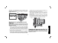
Cutting Depth Adjustment (Fig. 5, 6)
WARNING: To reduce the risk of serious personal injury,
turn tool off and disconnect tool from power source before
making any adjustments or removing/installing attachments or
accessories.
1. Hold the saw firmly. Raise the depth adjustment lever (J) to
loosen and move shoe to obtain the desired depth of cut,
as shown. Make sure the depth adjustment lever has been
retightened (lowered) before operating the saw.
2. Your saw is equipped with a carbide tipped saw blade for long life
and efficient cutting.
3. Setting the saw at the proper cutting depth keeps blade friction
to a minimum, removes sawdust from between the blade teeth,
results in cooler, faster sawing and reduces the chance of
kickback. Align the appropriate mark on the depth adjustment
strap with triangle on the upper blade guard (K). Your depth is
set.
FIG. 5
FIG. 6
4. For the most efficient cutting action using a carbide tipped saw
blade, set the depth adjustment so that about one half of a tooth
projects below the surface of the wood to be cut.
5. A method of checking for the correct cutting depth is shown in
Figure 6. Lay a piece of the material you plan to cut along the
side of the blade, as shown in the figure, and observe how much
tooth projects beyond the material.
Bevel Angle Adjustment (Fig. 7, 8)
WARNING: To reduce the risk of serious personal injury,
turn tool off and disconnect tool from power source before
making any adjustments or removing/installing attachments or
accessories.
The full range of bevel adjustment on the DW367 is 0 to 50 degrees.
The pivot bracket is graduated in 5 degree increments.
On the DW368 and DW369, the full range of bevel adjustment is
0 to 56 degrees. The pivot bracket is graduated in increments of
1 degree.
There is a bevel angle adjustment mechanism (M) consisting of a
quadrant with a pointer (N) and a lever (L) on the front of the saw.
FIG. 7
L
M
TIGHTEN
LOOSEN
N

9
English
1. To set the saw for a bevel cut, raise the lever (L) or turn the knob
(O) to loosen the bevel adjustment.
2. Tilt the shoe to the desired angle by aligning the pointer with the
desired angle mark on the pivot bracket.
3. Retighten the bevel adjustment by lowering the lever or turning
the knob.
FIG. 8
O
DW367
Bevel Detent (Fig. 7, 8)
WARNING: To reduce the risk of serious personal injury,
turn tool off and disconnect tool from power source before
making any adjustments or removing/installing attachments or
accessories.
The DW367 has a bevel stop at 45 degrees. To set the bevel at an
angle greater than 45 degrees, tilt the shoe to 45 degrees, then slide
the knob and bolt into the upper slot. When you reach the desired
angle, tighten the knob.
The DW368 and DW369 are equipped with a bevel detent feature.
As you tilt the shoe you will hear a click and feel the shoe stop at both
22.5 and 45 degrees. If either of these is the desired angle, retighten
the lever (L) by lowering it. If you desire another angle, continue
tilting the shoe until the pointer aligns with the desired mark.
FIG. 9
0˚
45˚
1/4"
6.35 mm
1/2"
13 mm
Kerf Indicator (Fig. 9)
The front of the saw shoe has a kerf indicator for vertical and bevel
cutting. This indicator enables you to guide the saw along cutting
lines penciled on the material being cut. The indicator lines up with
the left (inner) side of the saw blade, which makes the slot or "kerf"
cut by the moving blade fall to the right of the indicator. The ribs
on the front of the DW368 and DW369 shoe are at 1/4" (6.35 mm)
spacing. The notches on the front of the shoe are at 1/2" (13 mm)
intervals.
OPERATION
WARNING: To reduce the risk of serious personal injury,
turn tool off and disconnect tool from power source before
making any adjustments or removing/installing attachments or
accessories.
Switch (Fig. 1)
Pull the trigger switch (B) to turn the motor on. Releasing the trigger
turns the motor off. This tool has no provision to lock the switch in the
on position, and the tool should never be locked on in any way.

10
English
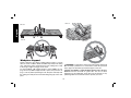
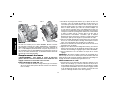
Workpiece Support
Figures 10 and 12 show proper sawing position. Figures 11 and 13
show an unsafe condition. Hands should be kept away from cutting
area, and power cord is positioned clear of the cutting area so that
it will not get caught or hung up on the work.
To avoid kickback, DO support board or panel NEAR the cut,
(Fig. 10 and 12). DON’T support board or panel away from the cut
(Fig. 11 and 13). When operating the saw, keep the cord away from
the cutting area and prevent it from becoming hung up on the work
piece.
FIG. 12
FIG. 10
FIG. 11
FIG. 13
WARNING: It is important to support the work properly and to hold
the saw firmly to prevent loss of control which could cause personal
injury; Figure 12 illustrates typical hand support of the saw.
ALWAYS DISCONNECT SAW BEFORE MAKING ANY ADJUST-
MENTS! Place the work with its “good” side - the one on which
appearance is most important - down. The saw cuts upward, so any
splintering will be on the work face that is up when you saw it.

11
English
Cutting
Support the work so that the waste will be on your right. Place the
wider portion of the saw shoe on that part of the work piece which
is solidly supported, not on the section that will fall off when the cut
is made. As examples, Figure 12 illustrates the RIGHT way to cut off
the end of a board, and Figure 13 the WRONG way. Always clamp
work. Don’t try to hold short pieces by hand! Remember to support
cantilevered and overhanging material. Use caution when sawing
material from below.
Be sure that the saw is up to full speed before blade contacts
material to be cut. Starting the saw with blade against material to be
cut or pushed forward into kerf can result in kickback.
Push the saw forward at a speed which allows the blade to cut
without laboring. Hardness and toughness can vary even in the
same piece of material, and knotty or damp sections can put a heavy
load on the saw. When this happens, push the saw more slowly, but
hard enough to keep it working without much decrease in speed.
Kickback
When the saw blade becomes pinched or twisted in the cut, kickback
can occur. The saw is thrust rapidly back toward the operator. When
the blade is pinched or bound tightly by the kerf closing down, the
blade stalls and the motor reaction drives the unit backward. When
the blade becomes twisted or misaligned in the cut, the teeth at
the back edge of the blade can dig into the top surface of the wood
causing the blade to climb out of the kerf and jump back toward the
operator.
Kickback is more likely to occur when any of the following conditions
exist.
1. IMPROPER WORKPIECE SUPPORT
A. Sagging or improper lifting of the cut off piece can cause
pinching of the blade and lead to kickback (Fig. 11).
B. Cutting through material supported at the outer ends only
can cause kickback. As the material weakens it sags, closing
down the kerf and pinching the blade.
C. Cutting off a cantilevered or overhanging piece of material
from the bottom up in a vertical direction can cause kickback.
The falling cut off piece can pinch the blade.
D. Cutting off long narrow strips (as in ripping) can cause
kickback. The cut off strip can sag or twist closing the kerf and
pinching the blade.
E. Snagging the lower guard on a surface below the material
being cut momentarily reduces operator control. The saw
can lift partially out of the cut increasing the chance of blade
twist.
2. IMPROPER DEPTH OF CUT SETTING ON SAW
To make the most efficient cut, the blade should protrude only
far enough to expose 1/2 of a tooth as shown in figure 5. This
allows the shoe to support the blade and minimizes twisting and
pinching in the material. See the section titled Cutting Depth
Adjustment.
3. BLADE TWISTING (MISALIGNMENT IN CUT)
A. Pushing harder to cut through a knot, a nail, or a hard grain
area can cause the blade to twist.
B. Trying to turn the saw in the cut (trying to get back on the
marked line) can cause blade twist.
C. Over-reaching or operating the saw with poor body control
(out of balance), can result in twisting the blade.
D. Changing hand grip or body position while cutting can result
in blade twist.
E. Backing up the saw to clear blade can lead to twist if it is not
done carefully.
4. MATERIALS THAT REQUIRE EXTRA ATTENTION
A. Wet lumber

12
English
B. Green lumber (material freshly cut or not kiln dried)
C. Pressure treated lumber (material treated with preservatives
or anti-rot chemicals)
5. USE OF DULL OR DIRTY BLADES
Dull blades cause increased loading of the saw. To compensate,
an operator will usually push harder which further loads the
unit and promotes twisting of the blade in the kerf. Worn blades
may also have insufficient body clearance which increases the
chance of binding and increased loading.
6. LIFTING THE SAW WHEN MAKING BEVEL CUTS
Bevel cuts require special operator attention to proper cutting
techniques – especially guidance of the saw. Both blade angle
to the shoe and greater blade surface in the material increase
the chance for binding and misalignment (twist) to occur.
7. RESTARTING A CUT WITH THE BLADE TEETH JAMMED
AGAINST THE MATERIAL
The saw should be brought up to full operating speed before
starting a cut or restarting a cut after the unit has been stopped
with the blade in the kerf. Failure to do so can cause stalling and
kickback.
Any other conditions which could result in pinching, binding,
twisting, or misalignment of the blade could cause kickback. Refer
to Additional Safety Instructions and Operation for procedures and
techniques that will minimize the occurrence of kickback.
MAINTENANCE
WARNING: To reduce the risk of serious personal injury,
turn tool off and disconnect tool from power source before
making any adjustments or removing/installing attachments or
accessories.
Cleaning
WARNING: Blow dirt and dust out of all air vents with clean, dry
air at least once a week. To minimize the risk of eye injury, always
wear ANSI Z87.1 approved eye protection when performing this.
WARNING: Never use solvents or other harsh chemicals for
cleaning the non-metallic parts of the tool. These chemicals may
weaken the plastic materials used in these parts. Use a cloth
dampened only with water and mild soap. Never let any liquid get
inside the tool; never immerse any part of the tool into a liquid.
Lubrication
Self lubricating ball and roller bearings are used in the tool and
relubrication is not required. However, it is recommended that, once
a year, you take or send the tool to a service center for a thorough
cleaning, inspection and lubrication of the gear case.
Electric Brake (DW369 Only)
Your saw has an automatic electric brake which is designed to stop
the blade from coasting in about two seconds, after you release the
trigger switch. It is useful when making certain cuts in wood where
a coasting blade would result in a wide, imprecise cut.
Occasionally, the brake will not function properly and won’t stop the
saw in the 2 seconds discussed above. If this condition persists,
turn the saw on and off four or five times. If the brake still does
not stop the blade in about 2 seconds, the problem may be worn
brushes. Replace the brushes as described below and try the
saw again. If the problem still persists, have the tool serviced at a
D
EWALT certified service center.
Repairs
To assure product SAFETY and RELIABILITY, repairs, maintenance
and adjustment should be performed by a D
EWALT factory service
center, a D
EWALT authorized service center or other qualified

13
English
service personnel. Always use identical replacement parts. (Refer to
Brushes for brush replacement information.)
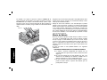
Brushes
WARNING: To reduce the risk of serious personal injury,
turn tool off and disconnect tool from power source before
making any adjustments or removing/installing attachments or
accessories.
Inspect carbon brushes regularly by unplugging tool, removing the
end cap and withdrawing the brush assembly. Keep brushes clean
and sliding freely in their guides. Always replace a used brush in the
same orientation in the holder as it was prior to removal. Carbon
brushes have varying symbols stamped into their sides, and if either
brush is worn down to the line closest to the spring, the brushes
must be replaced. Use only identical D
EWALT brushes. New brush
assemblies are available at your local service center. Always replace
the end cap after inspecting or servicing brushes. The tool should
be allowed to “run in” (run at no load without a blade) for 5 minutes
before use to seat new brushes.
While “running in” DO NOT TIE, TAPE, OR OTHERWISE LOCK THE
TRIGGER SWITCH ON. HOLD BY HAND ONLY.
Shoe Adjustment
WARNING: To reduce the risk of serious personal injury,
turn tool off and disconnect tool from power source before
making any adjustments or removing/installing attachments or
accessories.
Your shoe has been factory set to assure that the blade is perpen-
dicular to the shoe. If after extended use, you need to re-align the
blade follow the directions below:
ADJUSTING FOR 90 DEGREE CUTS
1. Return the saw to 0 degrees bevel.
2. Place the saw on its side, and retract the lower guard.
FIG. 14
3. Loosen the bevel adjustment lever (L). Place a square against
the blade and the shoe as shown in Figure 14.
4. Using a hex wrench, turn the set screw on the underside of the
shoe until the blade and the shoe are both in flush contact with
the square. Retighten the bevel adjustment lever.
ADJUSTING BEVEL ADJUSTMENT AND DEPTH
ADJUSTMENT LEVERS
It may be desirable to adjust the depth adjustment lever or the bevel
adjustment lever. They may loosen in time and hit the shoe before
tighten ing. To tighten the levers, follow the steps below.
ADJUSTING THE BEVEL ADJUSTMENT LEVER
(DW368, DW369)
NOTE: The following instructions also apply to adjusting the
DW367 and DW368 depth adjustment lever.
1. Using a small screwdriver, pry the lock ring off.
2. Remove the lever and rotate it in the desired direction about
1/8 of a revolution.
3. Reinstall the lock ring with the concave side against the lever.

14
English
ADJUSTING DEPTH ADJUSTMENT LEVER (DW369 ONLY)
1. Loosen the screw securing the depth adjustment lever.
2. Remove the depth adjustment lever and rotate it to the desired
location, about 1/8 of a revolution.
3. Tighten the lever screw.
Blades
A dull blade will cause inefficient cutting, overload on the saw
motor, excessive splintering and increase the possibility of kickback.
Change blades when it is no longer easy to push the saw through
the cut, when the motor is straining, or when excessive heat is built
up in the blade. It is a good practice to keep extra blades on hand
so that sharp blades are available for immediate use. Dull blades
can be sharpened in most areas; see SAWS-SHARPENING in the
yellow pages.
Hardened gum on the blade can be removed with kerosene,
turpentine, or oven cleaner. Anti-stick coated blades can be used
in applications where excessive build-up is encountered, such as
pressure treated and green lumber.
ACCESSORIES
WARNING: Since accessories, other than those offered by
D
EWALT, have not been tested with this product, use of such
accessories with this tool could be hazardous. To reduce the risk
of injury, only D
EWALT, recommended accessories should be used
with this product.
Recommended accessories for use with your tool are available
at extra cost from your local dealer or authorized service center.
If you need assistance in locating any accessory for your tool,
please contact D
EWALT Industrial Tool Co., 701 East Joppa Road,
Baltimore, MD 21286, call 1-800-4-D
EWALT (1-800-433-9258) or
visit our website www.dewalt.com.
DO NOT USE WATER FEED ATTACHMENTS WITH THIS SAW.
VISUALLY EXAMINE CARBIDE BLADES BEFORE USE. REPLACE
IF DAMAGED.
RECOMMENDED BLADE TYPES
COMBINATION FRAMING - 5/8" Round arbor, 24 teeth
All purpose fast rip and cross cuts.
PRESSURE TREATED/WET LUMBER - 5/8" Round arbor, 20 teeth
Coated - Resistant to gum build-up
EXTREME DURABILITY - 5/8" Round arbor, 18 teeth
Coated, rock carbide
FINISHING - 5/8" Round arbor, 36 teeth
More teeth for finer finish cuts.
FAST CUT FRAMING - 5/8" Round arbor, 16 teeth
Fastest blade for rips and cross cuts
Three Year Limited Warranty
DEWALT will repair, without charge, any defects due to faulty
materials or workmanship for three years from the date of purchase.
This warranty does not cover part failure due to normal wear or tool
abuse. For further detail of warranty coverage and warranty repair
information, visit www.dewalt.com or call 1-800-4-D
EWALT (1-800-
433-9258). This warranty does not apply to accessories or damage
caused where repairs have been made or attempted by others. This
warranty gives you specific legal rights and you may have other
rights which vary in certain states or provinces.
In addition to the warranty, D
EWALT tools are covered by our:
1 YEAR FREE SERVICE
D
EWALT will maintain the tool and replace worn parts caused by
normal use, for free, any time during the first year after purchase.

15
English
90 DAY MONEY BACK GUARANTEE
If you are not completely satisfied with the performance of your
D
EWALT Power Tool, Laser, or Nailer for any reason, you can return
it within 90 days from the date of purchase with a receipt for a full
refund – no questions asked.
LATIN AMERICA: This warranty does not apply to products sold
in Latin America. For products sold in Latin America, see country
specific warranty information contained either in the packaging, call
the local company or see website for warranty information.
FREE WARNING LABEL REPLACEMENT: If your warning labels
become illegible or are missing, call 1-800-4-D
EWALT (1-800-433-
9258) for a free replacement.
Page is loading ...
Page is loading ...
Page is loading ...
Page is loading ...
Page is loading ...
Page is loading ...
Page is loading ...
Page is loading ...
Page is loading ...
Page is loading ...
Page is loading ...
Page is loading ...
Page is loading ...
Page is loading ...
Page is loading ...
Page is loading ...
Page is loading ...
Page is loading ...
Page is loading ...
Page is loading ...
Page is loading ...
Page is loading ...
Page is loading ...
Page is loading ...
Page is loading ...
Page is loading ...
Page is loading ...
Page is loading ...
Page is loading ...
Page is loading ...
Page is loading ...
Page is loading ...
Page is loading ...
Page is loading ...
Page is loading ...
Page is loading ...
Page is loading ...
Page is loading ...

DEWALT Industrial Tool Co., 701 Joppa Road, Baltimore, MD 21286
(DEC09) Part No. N062614 DW367, DW368, DW369 Copyright © 2002–2006, 2009 D
EWALT
The following are trademarks for one or more D
EWALT power tools: the yellow and black color scheme; the “D” shaped air intake grill; the array of
pyramids on the handgrip; the kit box configuration; and the array of lozenge-shaped humps on the surface of the tool.
-
 1
1
-
 2
2
-
 3
3
-
 4
4
-
 5
5
-
 6
6
-
 7
7
-
 8
8
-
 9
9
-
 10
10
-
 11
11
-
 12
12
-
 13
13
-
 14
14
-
 15
15
-
 16
16
-
 17
17
-
 18
18
-
 19
19
-
 20
20
-
 21
21
-
 22
22
-
 23
23
-
 24
24
-
 25
25
-
 26
26
-
 27
27
-
 28
28
-
 29
29
-
 30
30
-
 31
31
-
 32
32
-
 33
33
-
 34
34
-
 35
35
-
 36
36
-
 37
37
-
 38
38
-
 39
39
-
 40
40
-
 41
41
-
 42
42
-
 43
43
-
 44
44
-
 45
45
-
 46
46
-
 47
47
-
 48
48
-
 49
49
-
 50
50
-
 51
51
-
 52
52
-
 53
53
-
 54
54
-
 55
55
-
 56
56


Ask a question and I''ll find the answer in the document
Finding information in a document is now easier with AI
in other languages
- français: DeWalt DW367 Manuel utilisateur
- español: DeWalt DW367 Manual de usuario
Related papers
Other documents
-
Craftsman CMES510 Owner's manual
-
Craftsman CMES500 Owner's manual
-
BLACK DECKER BDECS300C Owner's manual
-
Milwaukee 6375-20 User manual
-
Black & Decker CS1015 User manual
-
-
-
-
Bostitch BTE300K User manual
-
BLACK+DECKER CS1014 User guide