
A
Hardware Review
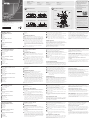
VE8900T / VE8950T Front View
1
HDMI Input Port
2
Audio Jack
3
IR Port
4
RS-232 Port
5
USB Type B
VE8900T / VE8950T Rear View
1
LAN Port
2
Power Jack
VE8900R / VE8950R Front View
1
USB Type A
2
RS-232 Port
3
Audio Jack
4
IR Port
5
HDMI Output Port
VE8900R / VE8950R Rear View
1
LAN Ports
2
Power Jack
B
Hardware Installation
1
Connect the HDMI Input Port on the VE8900T / VE8950T to the
HDMI Output Port on your video source device using HDMI cable.
2
Connect the HDMI Output Port on the VE8900R / VE8950R to the
HDMI Input Port on your video display device using HDMI Cable.
3
For point-to-point setups, connect one end of an RJ-45 cable to
the LAN port on the VE8900 / VE8950 Transmitter and connect
the other end of the same RJ-45 cable to the VE8900 / VE8950
Receiver’s LAN port. For multipoint-to-multipoint setups, connect
the VE8900 / VE8950 Transmitter and VE8900 / VE8950 Receiver's
LAN port via Rj-45 cable to the same local area network through a
router.
4
Plug the power adapter into the power jack on the VE8900/
VE8950 Transmitter and Receiver.
5
(Optional) Connect your computer or control system to the
RS-232 terminal blocks on the VE8900 / VE8950R.
6
(Optional) Connect an IR Transmitter/Receiver cable to the IR ports
on the VE8900 / VE8950’s Transmitter and Receiver.
7
(Optional) Connect USB peripherals via the VE8900 / VE8950’s USB
Ports
8
(Optional) Connect Audio devices via the Audio Jack port.
Note: You can connect RS-232 serial devices/peripherals to the
VE8900 / VE8950, such as touch screens and bar code scanners.
IP LAN Operation
The VE8900 / VE8950 is operated over an IP LAN. Setting up the
units on a network allows point-to-point, point-to-multipoint, and
multipoint-to-multipoint computer to console operation by connecting
multiple VE8900 / VE8950 devices on the same IP LAN.
The VE8900 / VE8950 can be transformed into a Video Matrix by
connecting to the LAN via a router allowing you to add multiple
Transmitters and Receivers to the setup.
Note: The router used must have IGMP
Web GUI
The VE8900 / VE8950 is controlled and managed through an intuitive
web GUI. It can be used to control all management of transmitters /
receivers and display layout settings via drag and drop.
Seven- Segment LED on both Transmitter and Receiver
There is a three digit seven segment LED on both the transmitter
and receiver. The ID is confi gured via the GUI or the top panel
pushbuttons. Use the ID to pair the Transmitter and Receivers over the
network.
VE8900 HDMI over IP Extender / VE8950 4K HDMI over IP Extender
www.aten.com
Extension HDMI sur IP VE8900 / Extension HDMI sur IP 4K VE8950
www.aten.com
HDMI-over-IP-Extender VE8900 / 4K-HDMI-over-IP-Extender VE8950
www.aten.com
Extensor KVM HDMI sobre IP VE8900 / Extensor 4K HDMI sobre IP VE8950
www.aten.com
Estensore HDMI su IP VE8900 / Estensore 4K HDMI su IP VE8950
www.aten.com
A
Présentation du matériel
Vue de face du VE8900T / VE8950T
1
Port d’entrée HDMI
2
Jack audio
3
Port IR
4
Port RS-232
5
USB Type B
Vue de dos du VE8900T / VE8950T
1
Port LAN
2
Fiche d'alimentation
Vue de face du VE8900R / VE8950R
1
USB Type A
2
Port RS-232
3
Jack audio
4
Port IR
5
Port de sortie HDMI
Vue de dos du VE8900R / VE8950R
1
Ports LAN
2
Fiche d'alimentation
B
Installation du matériel
1
Raccordez le port d’entrée HDMI du VE8900T / VE8950T au port
de sortie HDMI sur votre appareil source vidéo à l’aide du câble
HDMI.
2
Raccordez le port de sortie HDMI du VE8900R / VE8950R au port
d’entrée HDMI sur votre périphérique d’affi chage vidéo à l’aide du
câble HDMI.
3
Pour les confi gurations point à point, raccordez une extrémité
d’un câble RJ-45 au port LAN de l’émetteur VE8900 / VE8950 et
raccordez l’autre extrémité du même câble RJ-45 au port LAN du
récepteur VE8900 / VE8950. Pour les confi gurations multipoint à
multipoint, raccordez le port LAN de l’émetteur VE8900 / VE8950
et du récepteur VE8900 / VE8950 via un câble RJ-45 au même
réseau local via un routeur.
4
Branchez l’adaptateur secteur sur la prise d’alimentation de
l’émetteur et du récepteur VE8900/VE8950.
5
(Optionnel) Raccordez votre ordinateur ou votre système de
contrôle aux borniers RS-232 du VE8900 / VE8950R.
6
(Optionnel) Raccordez un câble émetteur / récepteur IR aux ports IR
de l’émetteur et du récepteur du VE8900 / VE8950.
7
(Optionnel) Connectez les périphériques USB via les ports USB du
VE8900 / VE8950
8
(Optionnel) Connectez les périphériques audio via le port jack
audio.
Remarque : Vous pouvez raccorder des dispositifs / périphériques
série RS-232 au VE8900 / VE8950, par exemple des
écrans tactiles et des scanners de codes-barres.
Fonctionnement LAN IP
Le VE8900 / VE8950 fonctionner via un LAN IP. Confi gurer les unités
sur un réseau permet un fonctionnement de l'ordinateur vers la
console point à point, point à multipoint et multipoint à multipoint en
connectant plusieurs appareils VE8900 / VE8950 sur le même LAN IP.
Le VE8900 / VE8950 peut être transformé en une matrice vidéo en se
connectant au LAN via un routeur qui vous permet d’ajouter plusieurs
émetteurs et récepteurs à la confi guration.
Remarque : Le routeur utilisé doit avoir IGMP
Interface graphique utilisateur Web
Le VE8900 / VE8950 se contrôle et se gère via une interface graphique
utilisateur Web conviviale. Elle peut être utilisée pour contrôler toute
la gestion des émetteurs / récepteurs et les réglages de disposition des
affi chages par glisser et déposer.
Affi cheurs LED sept segments sur l’émetteur et le
récepteur
L’émetteur et le récepteur disposent d'un affi cheur LED sept segments
sur 3 chiffres. L’ID se confi gure par l’interface graphique ou via les
boutons du panneau supérieur. Utilisez l’ID pour appairer l’émetteur
et le récepteur via le réseau.
A
Hardwareübersicht
VE8900T / VE8950T – Ansicht von vorne
1
HDMI-Eingang
2
Audioanschluss
3
IR-Anschluss
4
RS-232-Anschluss
5
USB, Typ B
VE8900T / VE8950T – Ansicht von hinten
1
LAN-Anschluss
2
Netzanschluss
VE8900R / VE8950R – Ansicht von vorne
1
USB, Typ A
2
RS-232-Anschluss
3
Audioanschluss
4
IR-Anschluss
5
HDMI-Ausgang
VE8900R / VE8950R – Ansicht von hinten
1
LAN-Anschlüsse
2
Netzanschluss
B
Hardwareinstallation
1
Verbinden Sie den HDMI-Eingang am VE8900T / VE8950T
per HDMI-Kabel mit dem HDMI-Ausgang an Ihrem
Videoeingangsgerät.
2
Verbinden Sie den HDMI-Ausgang am VE8900R / VE8950R per
HDMI-Kabel mit dem HDMI-Eingang an Ihrem Videoanzeigegerät.
3
Verbinden Sie für Point-to-Point-Einrichtungen ein Ende eines
RJ-45-Kabels mit dem LAN-Anschluss am Sender VE8900 / VE8950
und das andere Ende mit dem LAN-Anschluss am Empfänger
VE8900 / VE8950. Verbinden Sie bei Multipoint-to-Multipoint-
Einrichtungen den LAN-Anschluss des Senders VE8900 / VE8950
und den LAN-Anschluss des Empfängers VE8900 / VE8950 per
RJ-45-Kabel mit demselben lokalen Netzwerk über einen Router.
4
Schließen Sie das Netzteil an den Netzanschluss an Sender und
Empfänger VE8900/VE8950 an.
5
(Optional) Verbinden Sie Ihren Computer oder Ihr Steuerungssystem
mit den RS-232-Anschlussblöcken am VE8900 / VE8950R.
6
(Optional) Verbinden Sie ein IR-Sender/Empfänger-Kabel mit den
IR-Anschlüssen am Sender und Empfänger VE8900 / VE8950.
7
(Optional) Verbinden Sie USB-Peripherie über die USB-Anschlüsse
am VE8900 / VE8950
8
(Optional) Verbinden Sie Audiogeräte über den Audioanschluss.
Hinweis: Sie können serielle RS-232-Geräte/Peripherie mit dem
VE8900 / VE8950 verbinden, wie z. B. Touchscreens oder
Strichcodescanner.
IP-LAN-Bedienung
Das VE8900 / VE8950 wird über ein IP-LAN bedient. Die Einrichtung
der Geräte in einem Netzwerk ermöglicht durch Verbindung mehrerer
Geräte VE8900 / VE8950 mit demselben IP-LAN Point-to-Point-, Point-
to-Multipoint- und Multipoint-to-Multipoint-Betrieb von Computer zu
Konsole.
Der VE8900 / VE8950 kann durch Verbindung mit dem LAN über
einen Router in eine Videomatrix verwandelt werden, wodurch Sie der
Konfi guration mehrere Sender und Empfänger zufügen können.
Hinweis: Der verwendete Router muss IGMP haben
Web-Benutzeroberfl äche
Der VE8900 / VE8950 wird über eine intuitive Web-
Benutzeroberfl äche gesteuert und verwaltet. Sie kann zur Steuerung
der gesamten Verwaltung von Sendern / Empfängern und
Anzeigelayouteinstellungen per Ziehen-und-Ablegen genutzt werden.
Siebenteilige LED an Sender und Empfänger
An Sender und Empfänger befi ndet sich eine dreistellige siebenteilige
LED. Die ID wird per Benutzeroberfl äche oder über die Drucktasten an
der oberen Blende konfi guriert. Verwenden Sie die ID zur Kopplung
von Sender und Empfängern über das Netzwerk.
A
Resumen de hardware
Vista frontal VE8900T / VE8950T
1
Puerto de entrada HDMI
2
Conector de audio
3
Puerto IR
4
Puerto RS-232
5
USB Tipo B
Vista posterior VE8900T / VE8950T
1
Puerto LAN
2
Conector de alimentación
Vista frontal VE8900R / VE8950R
1
USB Tipo A
2
Puerto RS-232
3
Conector de audio
4
Puerto IR
5
Puerto de salida HDMI
Vista posterior VE8900R / VE8950R
1
Puertos LAN
2
Conector de alimentación
B
Instalación del hardware
1
Conecte el puerto de entrada HDMI del VE8900T / VE8950T al
puerto de salida HDMI del dispositivo fuente de vídeo mediante el
cable HDMI.
2
Conecte el puerto de salida HDMI del VE8900R / VE8950R al
puerto de entrada HDMI del dispositivo de visualización de vídeo
mediante el cable HDMI.
3
Para las confi guraciones punto a punto, conecte un extremo de
un cable RJ-45 al puerto LAN del transmisor VE8900 / VE8950 y
conecte el otro extremo del mismo cable RJ-45 al puerto LAN del
receptor VE8900 / VE8950. Para las confi guraciones multipunto
a multipunto, conecte el transmisor VE8900 / VE8950 y el puerto
LAN del receptor VE8900 / VE8950 a través de un cable RJ-45 a la
misma red de área local a través de un enrutador.
4
Enchufe el adaptador de alimentación en la toma de alimentación
del transmisor y del receptor VE8900/VE8950.
5
(Opcional) Conecte su PC o sistema de control a los bloques de
terminales RS-232 del VE8900 / VE8950R.
6
(Opcional) Conecte un cable IR del transmisor/receptor a los
puertos IR del transmisor y receptor del VE8900 / VE8950.
7
(Opcional) Conecte los periféricos USB a través de los puertos USB
del VE8900 / VE8950
8
(Opcional) Conecte los dispositivos de audio a través del conector
del puerto de audio.
Nota: Puede conectar dispositivos serie/periféricos RS-232 al VE8900 /
VE8950, como pantallas táctiles y escáneres de códigos de
barras.
Funcionamiento IP LAN
El VE8900 / VE8950 funciona a través de una LAN IP. La confi guración
de las unidades en una red permite que el PC punto a punto, punto
a multipunto y multipunto a multipunto conecte varios dispositivos
VE8900 / VE8950 en la misma LAN IP.
El VE8900 / VE8950 se puede transformar en una matriz de vídeo
mediante la conexión a la LAN a través de un enrutador que le
permite agregar múltiples transmisores y receptores a la confi guración.
Nota: El enrutador utilizado debe tener IGMP
Web GUI (Interfaz gráfi ca de usuario)
El VE8900 / VE8950 es controlado y gestionado a través de una
intuitiva interfaz gráfi ca de usuario web. Se puede utilizar para
controlar toda la gestión de transmisores / receptores y los ajustes de
presentación de pantalla a través de la función arrastrar y soltar.
Existe un LED de siete segmentos tanto en el transmisor
como en el receptor
Hay un LED de tres dígitos y siete segmentos tanto en el transmisor
como en el receptor. El ID se confi gura a través de la GUI o de los
pulsadores del panel superior. Utilice el ID para emparejar el transmisor
y los receptores a través de la red.
A
Descrizione hardware
Vista anteriore VE8900T / VE8950T
1
Porta di ingresso HDMI
2
Presa Audio
3
Port Infrarossi
4
Porta RS-232
5
USB Tipo B
Vista posteriore VE8900T / VE8950T
1
Porta LAN
2
Connettore di alimentazione
Vista anteriore VE8900R / VE8950R
1
USB Tipo A
2
Porta RS-232
3
Presa Audio
4
Port Infrarossi
5
Porta uscita HDMI
Vista posteriore VE8900R / VE8950R
1
Porte LAN
2
Connettore di alimentazione
B
Installazione dell'hardware
1
Collegare la porta di ingresso HDMI di VE8900T / VE8950T alla
porta di uscita HDMI sul dispositivo con la sorgente video usando il
cavo HDMI.
2
Collegare la porta di uscita HDMI di VE8900T / VE8950T alla porta
di ingresso HDMI sul dispositivo con la sorgente video usando il
cavo HDMI.
3
Per le confi gurazioni da punto a punto, collegare un'estremità di
un cavo RJ-45 alla porta LAN del trasmettitore VE8900 / VE8950
e collegare l'altra estremità dello stesso cavo RJ-45 alla porta LAN
del ricevitore VE8900 / VE8950. Per le confi gurazioni multi punto a
multi punto, collegare il trasmettitore VE8900 / VE8950 e la porta
LAN del ricevitore VE8900 / VE8950 utilizzando il cavo RJ-45 alla
stessa rete locale utilizzando un router.
4
Collegare l'adattatore di alimentazione alla presa di alimentazione
del trasmettitore e del ricevitore di VE8900/VE8950.
5
(Opzionale) Collegare il computer o il sistema di controllo alle
RS-232 di VE8900 / VE8950R.
6
(Opzionale) Collegare un cavo Trasmettitore/Ricevitore infrarossi
alle porte infrarossi sul Trasmettitore e sul ricevitore di VE8900 /
VE8950.
7
(Opzionale) Collegare le periferiche USB utilizzando le porte USB di
VE8900 / VE8950
8
(Opzionale) Collegare i dispositivi audio utilizzando gli ingressi
audio.
Nota: È possibile collegare dispositivi/periferiche seriali RS-232 a
VE8900 / VE8950, quali schermi a sfi oramento e scanner per
codice a barre.
Funzionamento su LAN con IP
VE8900 / VE8950 sono gestiti tramite LAN con IP. Se le unità vengono
confi gurate in una rete, è possibile avere collegamenti punto a punto,
e multi punto a multi punto alla console collegando più dispositivi
VE8900 / VE8950 sulla stessa LAN con IP.
VE8900 / VE8950 può essere trasformato in un Video Matrix
eseguendo un collegamento alla LAN tramite router in modo da poter
aggiungere più Trasmettitori e Ricevitori alla confi gurazione.
Nota: Il router utilizzato deve essere dotato di IGMP
Interfaccia utente grafi ca web
VE8900 / VE8950 sono controllati e gestiti da un'interfaccia utente
grafi ca web intuitiva. Può essere usata per gestire tutti i trasmettitori /
ricevitori e le impostazioni di visualizzazione tramite trascinamento.
LED con sette segmenti sia sul Trasmettitore che sul
Ricevitore
Sia sul trasmettitore che sul ricevitore è presente uno schermo LED a
tre cifre e sette segmenti. L'ID viene confi gurato attraverso l'interfaccia
utente grafi ca o attraverso i tasti presenti nella porte superiore del
pannello. Usare l'ID per associare il Trasmettitore e il Ricevitore sulla
rete.
5
1
2
4
1
2
3
5
1
2
4
1
2
3
B
Package Contents
VE8900T
1 VE8900 HDMI over IP Transmitter
1 RS232 Terminal block
1 5V Power adapter
1 User instructions
VE8900T / VE8950T Front View VE8900T / VE8950T Rear View
VE8900R / VE8950R Front View VE8900R / VE8950R Rear View
Hardware Installation
© Copyright 2017 ATEN
®
International Co., Ltd.
ATEN and the ATEN logo are trademarks of ATEN International Co., Ltd. All rights reserved. All
other trademarks are the property of their respective owners.
This product is RoHS compliant.
Part No. PAPE-1223-H90G Printing Date: 05/2017
4K HDMI over IP Extender
Quick Start Guide
HDMI over IP Extender
VE8950
VE8900
ATEN VanCryst
™
VE8900R
1 VE8900 HDMI over IP Receiver
1 RS232 Terminal block
1 5V Power adapter
1 User instructions
VE8950T
1 VE8950 4K HDMI over IP Transmitter
1 RS232 Terminal block
1 5V Power adapter
1 User instructions
VE8950R
1 VE8950 4K HDMI over IP Receiver
1 RS232 Terminal block
1 5V Power adapter
1 User instructions
Serial Device
Remote HDMI
device
HDMI Source
Device
VE8900R
VE8900T
HDMI Display
RS-232 to
Serial Device
IR Transmitter
Audio Player
Audio Speaker
1
2
3
5
5
6
7
7
8
8
6
7
4
4
Support and Documentation Notice
All information, documentation, fi rmware,
software utilities, and specifi cations
contained in this package are subject to
change without prior notifi cation by
the manufacturer.
To reduce the environmental impact of our
products, ATEN documentation and software
can be found online at
http://www.aten.com/download/
Technical Support
www.aten.com/support
이 기기는 업무용(A급) 전자파적합기기로서 판매자 또는
사용자는 이 점을 주의하시기 바라며, 가정외의 지역에
서 사용하는 것을 목적으로 합니다.
Scan for
more information
EMC Information
FEDERAL COMMUNICATIONS COMMISSION INTERFERENCE
STATEMENT:
This equipment has been tested and found to comply with the limits
for a Class A digital device, pursuant to Part 15 of the FCC Rules.
These limits are designed to provide reasonable protection against
harmful interference when the equipment is operated in a commercial
environment. This equipment generates, uses, and can radiate radio
frequency energy and, if not installed and used in accordance with
the instruction manual, may cause harmful interference to radio
communications. Operation of this equipment in a residential area
is likely to cause harmful interference in which case the user will be
required to correct the interference at his own expense.
FCC Caution: Any changes or modifi cations not expressly approved by
the party responsible for compliance could void the user's authority to
operate this equipment.
Warning: Operation of this equipment in a residential environment
could cause radio interference.
Warning: This equipment is compliant with Class A of CISPR 32. In a
residential environment this equipment may cause radio interference.
Suggestion: Shielded twisted pair (STP) cables must be used with the
unit to ensure compliance with FCC & CE standards.
This device complies with Part 15 of the FCC Rules. Operation is subject
to the following two conditions:(1) this device mat not cause harmful
interference, and(2) this device must accept any interference received,
including interference that may cause undesired operation.
A
Hardware Review
Page is loading ...
-
 1
1
-
 2
2


Ask a question and I''ll find the answer in the document
Finding information in a document is now easier with AI
in other languages
- italiano: ATEN VE8950T Guida Rapida
- français: ATEN VE8950T Guide de démarrage rapide
- español: ATEN VE8950T Guía de inicio rápido
- Deutsch: ATEN VE8950T Schnellstartanleitung
- русский: ATEN VE8950T Инструкция по началу работы
- português: ATEN VE8950T Guia rápido
- 日本語: ATEN VE8950T クイックスタートガイド
Related papers
Other documents
-
Lindy 38066 User manual
-
Asus WAVI User manual
-
Infocus INA-SIMPS1 User guide
-
Antec Multimedia Station E-Z Installation guide
-
Asus CM6870 User manual
-
LG 75UW341C User manual
-
LG 32LW341H(EU) User manual
-
LG 32LW300C(CIS) User manual
-
Tripp Lite B127F-1A1-MM-DD & B127F-1A1-SM-DD Owner's manual
-
LG 43LV340C Owner's manual