Page is loading ...

PIANO DI COTTURA ELETTROGAS FILOTOP TOUCH
IT
Installazione - Uso - Manutenzione [3-14]
COOKING HOB ELECTROGAS FILOTOP TOUCH
GB
Installation - Use - Maintenance [15-26]
TABLES DE CUISSON ÉLECTROGAZ FILOTOP TOUCH
FR
Installation - Emploi - Entretien [27-38]
EINBAUKOCHGERÄT ELEKTRO FILOTOP TOUCH
DE
Installation - Gebrauch - Wartung [39-50]
PLACA DE COCCIÓN ELECTROGAS FILOTOP TOUCH
ES
Instalación - Uso - Mantenimiento [51-62]
MESAS DE ENCASTRAR ELECTROGÁS FILOTOP TOUCH
PT
Instalação - Uso - Manutenção [63-74]
Contact details - Page 75
Page is loading ...
Page is loading ...
Page is loading ...
Page is loading ...
Page is loading ...
Page is loading ...
Page is loading ...
Page is loading ...
Page is loading ...
Page is loading ...
Page is loading ...

1514
I
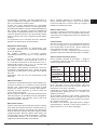
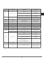
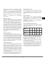
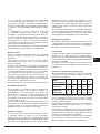
CARATTERISTICHE UTILIZZATORI
BRUCIATORI GAS
ALIMENTAZIONE
TIPO PRESSIONE mbar
NORM.
BRUCIATORE
Ø INIETTORE
1/100
PORTATA
TERMICA
NOMINALE
CONSUMO
Gas naturale G20 20
rapido 129 3000 286
l/h
semirapido 101 1750 167
ausiliario 77 1000 95
corona 3 150 4000 381
Gas liquido G30/G31 28-30/37
rapido 87 3000 218
g/h
semirapido 66 1750 127
ausiliario 50 1000 73
corona 3 102 4000 291
Gas naturale G25 25
rapido 132 3000 332
l/h
semirapido 102 1750 194
ausiliario 80 1000 111
corona 3 160 4000 443
G20 10
rapido 155 3000 286
l/h
semirapido 117 1750 167
ausiliario 92 1000 95
corona 3 180 4000 381

15
GB
14
Index
Instructionsfor use
Installation, 16
Use, 16
Maintenance, 19
Instructions for the installater
Installation, 20
Gas connection, 23
Electrical connection, 23
User characteristics, 26
THIS APPLIANCE IS CONCEIVED FOR
DOMESTIC USE ONLY.
THE MANUFACTURER SHALL NOT IN
ANY WAY BE HELD RESPONSIBLE FOR
WHATEVER INJURIES OR DAMAGES ARE
CAUSED BY INCORRECT INSTALLATION OR
BY UNSUITABLE, WRONG OR ABSURD USE.
THIS APPLIANCE IS NOT INTENDED FOR
USE BY PERSONS (INCLUDING CHILDREN)
WITH REDUCED PHYSICAL, SENSORY
OR MENTAL CAPABILITIES, OR LACK OF
EXPERIENCE AND KNOWLEDGE, UNLESS
THEY HAVE BEEN GIVEN SUPERVISION OR
INSTRUCTION CONCERNING USE OF THE
APPLIANCE BY A PERSON RESPONSIBLE
FOR THEIR SAFETY.
CHILDREN SHOULD BE SUPERVISED TO
ENSURE THAT THEY DO NOT PLAY WITH THE
APPLIANCE.
Dear customer,
We thank you and congratulate you on your
choice.
This new carefully designed product,
manufactured with the highest quality
materials, has been carefully tested to
satisfy all your cooking demands.
We would therefore request you to read
and follow these easy instructions which will
allow you to obtain excellent results right
from the start.
May we wish you all the very best with your
modern appliance!
THE MANUFACTURER
Italiano
I
GB
English
FR
Français
DE
ES
Deutsch
Español
PT
Português

16 17
GB
Installation
All the operations concerned with the installation
(electrical and gas connections, adaptation to type of
gas, necessary adjustments, etc.) must be carried out
by qualified technicians, in terms with the standards
in force. For specific instructions, kindly read the part
reserved for the installation technician.
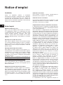
Use
Standby mode (Fig. 1-2-3)
When the device is turned on, it performs a brief self-test
and calibrates the touch-pad (all displays and LEDs turn
on for several seconds). At the end, the display will be
completely off. In this mode, the device can be turned on
by simply pressing the ON/OFF key.
Turning on the Cooking Surface
To turn on the device, you must hold down the ON/
OFF key for at least 2 seconds. The device will turn on
and the burner displays will display level zero, which
corresponds to burner off.
Turning on a burner
To turn on a burner, press the relative + and - keys on the
control panel. The keys must be pressed simultaneously
and held down for at least 1 second. When the burner
turns on, the burner will be set to the average flow and
the relative display will show level 3.
Each burner whose timer has not been programmed
will automatically turn off after 4 hours of continuous
operation.
The turning on of the burner is also indicated by the
relative LED near the timer display, which will be on for
the entire time that the burner is on.
Adjusting the flame level of a burner
To increase the flow to a burner that is on, press the
+ key and to decrease the flow, press the - key. For a
continuous change in the flow level, just hold down the +
or - key and release it at the desired level. The flow level
varies form 1 to 5.
Turning off a burner
To turn a burner off, press the + and - keys simultaneously
for a brief instant.
Turning off all the burners
To turn all the burners off at the same time, briefly press
the ON/OFF key; this puts the device in standby mode.
Programming the amount of time after which the
burner turns off
A time, after which a burner turns off, can be set
independently for each burner.
To program a burner timer, press the PT key. In the
part of the control panel that shows the position of each
burner with an LED, the burner A indicator (LED-A)
lights to indicate that burner A is currently selected for
programming. Use the P+ and P- keys to select the timer
of the burner to be programmed. The selected burner is
indicated by the flashing of its light. The timer display
shows 0.00 to indicate that the timer for the selected
burner is not active. To program the turn-off time for
the selected burner, press the PT key again; the timer
display will show 0.00. The flashing digit to the left of the
decimal point indicates hours while the digits to the right
indicate minutes. By pressing the P+ or P- keys, you can
increase, or decrease, the number of operating hours
from 0 to 9. When you hold down the P+ or P- keys, the
change of hours is continuous.
To specify the number of minutes, press PT again. The
digit to the right of the decimal point flashes. Set the
minutes the same way as the hours.
When programming the time, you can zero the current
setting at any time by pressing the P+ and P- keys
together. When a time of zero is set, the burner timer is
deactivated. To confirm the time displayed, press the PT
key. At this point, the only burner LEDs that are flashing
are those whose timers are running.
By pressing the PT key, you can return to timer
programming mode to see how much time remains
before the burner turns off or to change the current
setting. If, during programming, no key is pressed for
longer than 10 seconds, programming is automatically
interrupted and the main display returns. Any settings
that were made for the selected burner are stored and
the relative timer is running.
A timer can be set whether a burner is on or off and the
countdown starts immediately after the time setting is
confirmed. When the countdown ends, the timed burner
will turn off and a sequence of beeps will sound for 30
seconds. This sequence can be interrupted by pressing
the PT key.
When you turn off a burner, its timer is also deactivated.
Setting the clock
After a power failure, the time displayed by the clock
inside the device must be reset.
To set the clock, you must press the PT, P+ and P- keys
simultaneously for at least 3 seconds.
The flashing digit to the left of the decimal point indicates
hours while the digits to the right indicate minutes.
Pressing the P+ or P- keys increases or decreases the
hours and, when you hold down the P+ or P- key, the
number of hours changes continuously.
Press the PT key again to set the minutes. The digits
Instructions for use

16 17
GB
to the right of the decimal point will flash and you can
change the minutes in the same way described for the
hours.
When you press PT, the time setting will be saved.
Unlocking the burners
When a burner is locked, the relative display shows the
letter “b”. To unlock, hold down the burner A key and
the KL key for at least 2 seconds. After being unlocked,
the burners will be reset to level 0, ready to be turned
on again.
Note: If you have to repeat the unlock procedure 5
consecutive times in a period of 15 minutes, the device
will display FT06 and will not allow any more unlocks for
another 15 minutes.
Locking the keypad
This is activated by pressing just the KL key for at least 2
seconds. All the burners will remain at the current level.
The status of the keypad is indicated by the lighting of the
decimal points in the flow level displays for each burner.
When the keypad is locked, it is not possible to change
the levels of the burners or change the timer settings but
it is possible to turn off the surface by pressing the ON/
OFF key.
It is not possible to unlock a locked burner while the
keypad is locked. For this reason, you must unlock the
keypad before unlocking the burners.
Unlocking the keypad
To unlock the keypad, press the KL key and the + key
of burner A for at least 2 seconds. When the keypad is
unlocked, the decimal points in the level displays turn
off.
Residual Heat
When a burner goes out, the relative display shows an
"H" to indicate that the temperature of that burner is still
high and the relative LED near the timer display remains
on.
The "H" symbol and the LED turn off when the
temperature of the relative burner is cool.
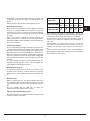
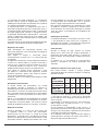
Special slow cooking (Duty cycle)
This function turns any cook top burner on and off is the
sequence shown in the table.
LEVEL SET. 1 2 3 4 5
TURN-OFF TIME
10
Sec.
20
Sec.
30
Sec.
40
Sec.
50
Sec.
TURN-ON TIME
50
Sec.
40
Sec.
30
Sec.
20
Sec.
10
Sec.
The function is activated by pressing the + key of the
burner you want to apply it to, and the PT key (the burner
involved must be off when this function is activated).
The burner turns on at level 3 and, at that time, you can
set the level to apply the function to by pressing the +
and - keys.
If, for example, you set the value to level 1, the burner
will remain on for 50 seconds, then it will turn off for 10
seconds and repeat this cycle until you turn the burner
off.
If the user does not intervene it turns off automatically
after 60 minutes. When this function is active the display
of the relative burner flashes.

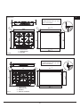
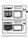
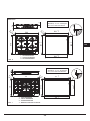
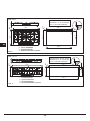
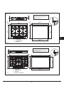
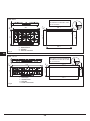
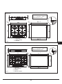
18 19
GB
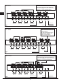
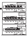
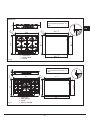
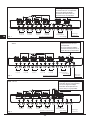
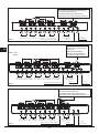
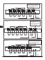
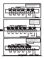
Turning
ON/OFF
Lock
Time activation
The lighting of an LED means
that the function is active for
that burner.
A flashing LED indicates that
the timer of the relative burner
has been activated.
Setting
burner A
Setting
burner B
Setting
burner C
Setting
burner D
Setting
burner E
Timer
setting
Fig. 1
Fig. 2
Fig. 3
Mod: 60 cm
Mod: 77 cm
90 cm
Mod: 112 cm
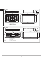
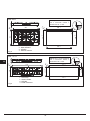
Setting
burner A
Setting
burner B
Setting
burner C
Setting
burner D
Timer
setting
Turning
ON/OFF
Lock
Time activation
Setting
burner A
Setting
burner B
Setting
burner C
Setting
burner D
Timer
setting
Turning
ON/OFF
Lock
Time activation
The lighting of an LED means that the
function is active for that burner.
A flashing LED indicates that the timer of
the relative burner has been activated.
The lighting of an LED means that the
function is active for that burner.
A flashing LED indicates that the timer of
the relative burner has been activated.

18 19
GB
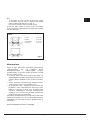
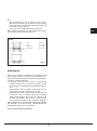
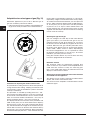
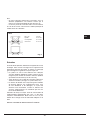
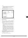
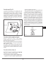
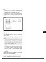
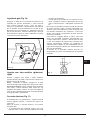
N.B
- We recommend the use of pots and pans with a
diameter matching that of the burner, thus preventing
the flame from escaping from the bottom part and
surrounding the pot (Fig. 4);
- do not leave any empty pots or pans on the fire;
When cooking is finished, it is also a good norm to close
the main gas pipe tap and/or cylinder.
fish 20x32
fast Ø 20-26
semifast Ø 14-20
auxiliary* Ø 10-14
GAS
Fig. 4
Maintenance
Prior to any operation, disconnect the appliance from
the electrical system. For long-life to the equipment, a
general cleaning operation must take place periodically,
bearing in mind the following:
• the glass and steel parts must be cleaned with
suitable non-abrasive or corrosive products (found
on the market). Avoid chlorine-base products (bleach,
etc.);
• avoid leaving acid or alkaline substances on the
working area (vinegar, salt, lemonjuice, etc.);
• thewallbafeandthesmallcovers(mobilepartsof
the burner) must be washed frequently with boiling
water and detergent, taking care to remove every
possible encrustation. Dry carefully and check that
none of the burner holes is fully or partially clogged;
heck periodically the state of conservation of the flexible
gas feed pipe. In case of leakage, call immediately the
qualified technicians for its replacement.
DO NOT USE STEAM CLEANERS

20 21
GB
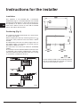
Instructions for the installer
Installation
This appliance is not provided with a combustion
product discharge. It is recommended that it be installed
insufficiently aerated places, in terms of the laws in force.
The quantity of air which is necessary for combustion
must not be below 2.0 m
3
/h for each kW of installed
power. See table of burner power.
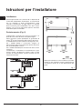
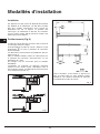
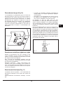
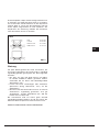
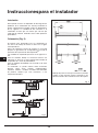
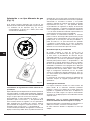
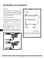
Positioning (Fig. 5)
The cook top is designed to be built in to a work surface
as shown in the figure.
Before installing the cook top, install the gasket seal
around the entire perimeter of the hole where it will be
inserted.
The dimensions of the hole are shown in figures 6-7-8-9.
For Filotop models, the perimeter of the hole must be
lowered by a depth of 1.5 mm.
The hole does not need to be milled for Semifilotop
models.
The cook top can be installed on different materials such
as brickwork, steel, marble, conglomerates, synthetics,
wood and wood covered with plastic laminates, so long
as resistant to a temperature of 90 °C.
Fig. 5
A panel made of wood or other insulating material
must be installed under the cook top at a distance
of at least 15 mm from the surface.

20 21
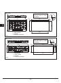
GB
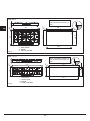
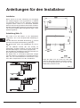
Fig. 6
591
+1
0
511
+1
0
560
+1
0
490
+1
0
R
1
2
1.5
590
510
R
1
1
74
1
1
3
2
2
Note: Semifilotop models do
not need to be lowered by 1.5
mm.
1 - AUXILIARY
2 - SEMI-RAPID
3 - RAPID
74
770
510
R
1
1
771
+1
0
511
+1
0
490
+1
0
750
+1
0
1.5
R
1
2
1
3 2
4
2
1 - AUXILIARY
2 - SEMI-RAPID
3 - RAPID
4 - TRIPLE CROWN
Note: Semifilotop models do
not need to be lowered by 1.5
mm.
Fig. 7
Mod: 60 cm
Mod: 77 cm

22 23
GB
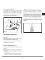
860
510
R
1
1
861
+1
0
511
+1
0
490
+1
0
840
+1
0
1.5
R
1
2
74
1
3 2
4
2
1 - AUXILIARY
2 - SEMI-RAPID
3 - RAPID
4 - TRIPLE CROWN
Note: Semifilotop models do
not need to be lowered by 1.5
mm.
Fig. 8
1120
R
1
1
1121
+1
0
385
+1
0
365
+1
0
1100
+1
0
1.5
R
1
2
74
384
1 34 2
1 - AUXILIARY
2 - SEMI-RAPID
3 - RAPID
4 - TRIPLE CROWN
Note: Semifilotop models do
not need to be lowered by 1.5
mm.
Fig. 9
Mod: 90 cm
Mod: 112 cm

22 23
GB
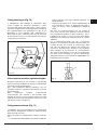
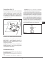
Gas connection (Fig. 10)
The connection to a gas tank or gas line must be made
by a qualified person in conformity to current updated
UNI-CIG 7129 and 7131 standards after making
sure that the cook top is prepared for the type of gas
available. If not, see: “Adapting to different types of gas”.
Also check that the feed pressure falls within the values
shown in the table: “User characteristics”.
Fig. 10
Metal rigid/semi-rigid hook-ups
Make the hook-up with metal fittings and pipes (even
flexible hoses) so as not to stress the components inside
the cook top.
Note: - After installation, use soapy water to check the
perfect seal of the entire connection system.
Important note: make the connection using only metal
fittings and pipes (flexible, continuous-wall steel hoses
or rigid copper or steel tubing) and in such a way that its
entire length can be inspected.
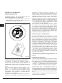
Electrical connection
(Fig. 11)
The installer must be qualified and is responsible for
correct electrical connections and following safety
standards.
Prior to carrying out the electrical connection, please
ensure that:
• theplantcharacteristicsaresuchastofollowwhatis
indicated on the matrix plate placed at the bottom of
the working area;
• thattheplantisttedwithanefcientearthconnection,
following the standards and law provisions in force.
The earth connectionis compulsory in terms of the
law.
Should there be no cable and/or plug on the equipment,
use suitable absorption material for the working
temperature as well, as indicated on the matrix
plate. Under no circumstance must the cable reach a
temperature above 50°C of the ambient temperature.
If connecting directly to the mains power supply, fit a
multi-pole switch of a suitable size for the rated capacity
with a clearance distance which completely disconnects
the power line under overvoltage category III conditions,
consistently with the rules of installation (the yellow/
green earth wir must not be interrupted). The plug or
omnipolar switch must be easily reached on the installed
equipment.
Fig. 11

24 25
GB
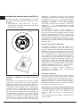
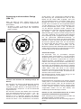
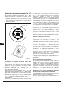
Adaptation to varius types of gas
(Fig. 12)
Should the appliance be pre-set for a different type of
gas than available, procreed as follows:
• replacetheinjector(Fig.7)withthecorrespondingtype
of gas to be used (see table “User characteristics“);
Wok only
Fig. 12
Procedure for adjusting the minimum burner flow
The procedure for setting minimums allows the operator to
change minimum flow setting, adapting each burner to the
characteristics of the gas distribution system to which the
cook top is hooked-up.
The procedure is activated by holding down the + and -
keys of burner A together with the + and - keys of burner D
for 3 seconds, with all the burners off for a 4-burner model
while, for a 5-burner model, hold down the + and - keys of
burner A together with the + and - keys of burner E.
The display indicates the activation of the procedure with
“MIN”. At this point, you can select the burner to adjust by
pressing the P+ and P- keys. After confirming with the PT
key, the selected burner will light at the minimum and you
will be able to increase or decrease the minimum flow by
pressing the + and - keys for that burner. During regulation,
the flame level display will show -, if the minimum set is the
factory setting, and will display a flashing ^ or v to indicate,
respectively, a higher or lower flow than the factory setting.
To confirm the minimum flow desired, you must press the
PT key. “MIN” will remain displayed and no LEDs will flash,
so, at this point, you can press PT to exit the procedure
or press the P+ or P- keys to select another burner and
set the minimum flow. The minimum flow levels are then
acquired and stored by the device and will be used during
normal use of the cook top.
Selecting the type of fuel gas
You can configure the cook top to work with different
gases (see table 1). To select the fuel gas to use, the
cook top must be on with all the burners off. Just press
the burner A, burner B and B- keys together for at least 2
seconds. When the fuel gas selection procedure starts,
the burner level display turns off and the timer display
shows “2020”, “3029”, “2525” or “2010”, depending on
the current configuration in use. It is possible to select
the desired setting with the P+ and P- keys. To end the
procedure, you must press the PT key.
Using this function deletes any turn-off times that may
have been programmed for the burners.
Electronic self-test
The electronic cards are continuously checking their
status. If there are any hardware or board problems that
could affect the end-user's safety, the cook top goes
into a “safe” mode which closes the solenoid valves and
displays a code relative to failure.
Warnings for correct functioning of the flame detection
circuit built-in to the appliance.
This device can be used in neutral phase 230V electric
circuits, with neutral connected to earth.
The device must be adapted if used with electric circuits
of different types.

24 25
GB
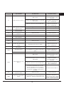
Error
displayed
Problem type Possible cause Possible solution
B Single burner locked
No gas
Restore the gas and unlock the
burners
Ionization electrode dirty or not hit by the flame
Clean or reposition the
electrode and unlock the
burners
The cook top is not grounded
Check the cables and unlock
the burners
F
Parasite flame/flame detection
circuit anomaly on the single
burner
Ionization electrode wired incorrectly Check the wiring
Failure at the circuit Replace the device
Flt00
Main valve control circuit
anomaly
Failure at the circuit Replace the device
Flt01
Anomaly circuit voltage of
reference
Failure at the circuit Replace the device
Flt02 Watchdog circuit anomaly Failure at the circuit Replace the device
Flt03 Microcontroller door anomaly Failure at the circuit Replace the device
Flt04 Eeprom anomaly Failure at the circuit Replace the device
Flt05 Pilot valve circuit anomaly Failure at the circuit Replace the device
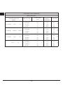
Flt06
Limit of 5 unlocks in 15
minutes exceeded
The burners have been unlocked 5 times in 15
minutes
Wait 15 minutes before
unlocking the burners
Flt08 Power supply circuit anomaly Failure at the circuit Replace the device
Flt09
Generic anomaly
Power was cut to the device when another type
of failure had occurred previously
Unlock the burners
Resonator anomaly Failure at the circuit Replace the device
Flt0A All burners locked
No gas
Restore the gas and unlock the
burners
Ionization electrodes dirty or not hit by the flame
Clean or reposition the
electrodes and unlock the
burners
The cook top is not grounded
Check the cables and unlock
the burners
Gas is leaking from one valve that caused the
unwanted lighting of a second burner while the
first was being lit.
This problem is caused by flame in the second
burner for more than 10 seconds.
Replace the defective valve
Flt0[
Communication errors in the
control logic
Failure at the circuit Replace the device
Flt0E
Error in the control of the
keypad
A mechanical deformation could have
compromised the support of the keypad by the
glass
Wait several seconds for the
keypad to recalibrate. If the
error persists, turn the power
off and on. If the error still
persists, replace the device.

2726
GB
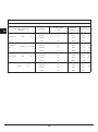
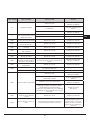
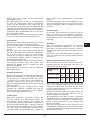
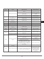
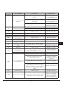
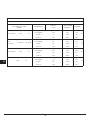
USER CHARACTERISTICS
GAS BURNERS
FEED
TYPE PRESSURE mbar
NORM.
BURNER
Ø INJECTORS
1/100
THERMAL
CAPACITY
CONSUMPTION
Natural gas G20 20
fast 129 3000 286
l/h
semifast 101 1750 167
auxiliary 77 1000 95
wok 3 150 4000 381
Liquefied
gas
G30/G31 28-30/37
fast 87 3000 218
g/h
semifast 66 1750 127
auxiliary 50 1000 73
wok 3 102 4000 291
Natural gas G25 25
fast 132 3000 332
l/h
semifast 102 1750 194
auxiliary 80 1000 111
wok 3 160 4000 443
G20 10
fast 155 3000 286
l/h
semifast 117 1750 167
auxiliary 92 1000 95
wok 3 180 4000 381
Page is loading ...
Page is loading ...
Page is loading ...
Page is loading ...
Page is loading ...
Page is loading ...

32 33
FR
Fig. 6
591
+1
0
511
+1
0
560
+1
0
490
+1
0
R
1
2
1.5
590
510
R
1
1
74
1
1
3
2
2
N.B. L’abaissement n’est pas
nécessaire pour la version
Semifilotop.
1 - AUXILIAIRE
2 - SEMI-RAPIDE
3 - RAPIDE
74
770
510
R
1
1
771
+1
0
511
+1
0
490
+1
0
750
+1
0
1.5
R
1
2
1
3 2
4
2
1 - AUXILIAIRE
2 - SEMI-RAPIDE
3 - RAPIDE
4 - TRIPLE COURONNE
N.B. L’abaissement n’est pas
nécessaire pour la version
Semifilotop.
Fig. 7
Mod: 60 cm
Mod: 77 cm

34 35
FR
860
510
R
1
1
861
+1
0
511
+1
0
490
+1
0
840
+1
0
1.5
R
1
2
74
1
3 2
4
2
1 - AUXILIAIRE
2 - SEMI-RAPIDE
3 - RAPIDE
4 - TRIPLE COURONNE
N.B. L’abaissement n’est pas
nécessaire pour la version
Semifilotop.
Fig. 8
1120
R
1
1
1121
+1
0
385
+1
0
365
+1
0
1100
+1
0
1.5
R
1
2
74
384
1 34 2
1 - AUXILIAIRE
2 - SEMI-RAPIDE
3 - RAPIDE
4 - TRIPLE COURONNE
N.B. L’abaissement n’est pas
nécessaire pour la version
Semifilotop.
Fig. 9
Mod: 90 cm
Mod: 112 cm
Page is loading ...
Page is loading ...
Page is loading ...

3938
FR
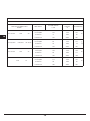
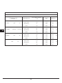
CARACTERISTIQUES UTILISATEURS
BRULEURES A GAZ
ALIMETATION
TYPE GASTOEVER mbar
NORM.
BRULEUR
Ø INJECTEURS
1/100
DEBIT THERMIQUE
NOMINAL
W
CONSOMMATION
Gaz naturel G20 20
rapide 129 3000 286
l/h
semirapide 101 1750 167
auxiliaires 77 1000 95
couronne 3 150 4000 381
Gaz liquéfié G30/G31 28-30/37
rapide 87 3000 218
g/h
semirapide 66 1750 127
auxiliaires 50 1000 73
couronne 3 102 4000 291
Gaz naturel G25 25
rapide 132 3000 332
l/h
semirapid 102 1750 194
auxiliaires 80 1000 111
couronne 3 160 4000 443
G20 10
rapide 155 3000 286
l/h
semirapide 117 1750 167
auxiliaires 92 1000 95
couronne 3 180 4000 381
Page is loading ...
Page is loading ...
Page is loading ...
Page is loading ...
Page is loading ...
Page is loading ...
Page is loading ...
Page is loading ...
Page is loading ...
Page is loading ...
Page is loading ...
Page is loading ...
Page is loading ...
Page is loading ...
Page is loading ...
Page is loading ...
Page is loading ...
Page is loading ...
Page is loading ...

58 59
ES
860
510
R
1
1
861
+1
0
511
+1
0
490
+1
0
840
+1
0
1.5
R
1
2
74
1
3 2
4
2
1 - AUXILIAR
2 - SEMIRÁPIDO
3 - RÁPIDO
4 - TRIPLE CORONA
N.B. Para la versión Semifilotop
la reducción en altura de 1,5 mm
no es necesaria.
Fig. 8
1120
R
1
1
1121
+1
0
385
+1
0
365
+1
0
1100
+1
0
1.5
R
1
2
74
384
1 34 2
1 - AUXILIAR
2 - SEMIRÁPIDO
3 - RÁPIDO
4 - TRIPLE CORONA
N.B. Para la versión Semifilotop
la reducción en altura de 1,5 mm
no es necesaria.
Fig. 9
Mod: 90 cm
Mod: 112 cm
Page is loading ...
Page is loading ...
Page is loading ...

6362
ES
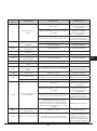
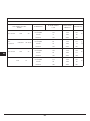
CARACTERISTICAS UTILIZADORES
QUEMADORES DE GAS
ALIMENTACION
TIPO PRESION mbar
NORM.
QUEMADOR
Ø INYECTORES
1/100
CAPACIDAD
TÉRMICA
CONSUMPTION
Gas natural G20 20
ràpido 129 3000 286
l/h
semiràpido 101 1750 167
auxiliar 77 1000 95
corona 3 150 4000 381
Gas
licuefacto
G30/G31 28-30/37
ràpido 87 3000 218
g/h
semiràpido 66 1750 127
auxiliar 50 1000 73
corona 3 102 4000 291
Gas natural G25 25
ràpido 132 3000 332
l/h
semiràpido 102 1750 194
auxiliar 80 1000 111
corona 3 160 4000 443
G20 10
ràpido 155 3000 286
l/h
semiràpido 117 1750 167
auxiliar 92 1000 95
corona 3 180 4000 381
Page is loading ...
Page is loading ...
Page is loading ...
Page is loading ...
Page is loading ...
Page is loading ...
Page is loading ...

70 71
PT
860
510
R
1
1
861
+1
0
511
+1
0
490
+1
0
840
+1
0
1.5
R
1
2
74
1
3 2
4
2
1 - AUXILIAR
2 - SEMI-RÁPIDO
3 - RÁPIDO
4 - TRIPLA COROA
NOTA: para a versão Semifilotop
não é necessário realizar o
abaixamento de 1,5 mm.
Fig. 8
1120
R
1
1
1121
+1
0
385
+1
0
365
+1
0
1100
+1
0
1.5
R
1
2
74
384
1 34 2
1 - AUXILIAR
2 - SEMI-RÁPIDO
3 - RÁPIDO
4 - TRIPLA COROA
NOTA: para a versão Semifilotop
não é necessário realizar o
abaixamento de 1,5 mm.
Fig. 9
Mod: 90 cm
Mod: 112 cm
Page is loading ...
Page is loading ...
Page is loading ...
Page is loading ...
Page is loading ...
Page is loading ...
-
 1
1
-
 2
2
-
 3
3
-
 4
4
-
 5
5
-
 6
6
-
 7
7
-
 8
8
-
 9
9
-
 10
10
-
 11
11
-
 12
12
-
 13
13
-
 14
14
-
 15
15
-
 16
16
-
 17
17
-
 18
18
-
 19
19
-
 20
20
-
 21
21
-
 22
22
-
 23
23
-
 24
24
-
 25
25
-
 26
26
-
 27
27
-
 28
28
-
 29
29
-
 30
30
-
 31
31
-
 32
32
-
 33
33
-
 34
34
-
 35
35
-
 36
36
-
 37
37
-
 38
38
-
 39
39
-
 40
40
-
 41
41
-
 42
42
-
 43
43
-
 44
44
-
 45
45
-
 46
46
-
 47
47
-
 48
48
-
 49
49
-
 50
50
-
 51
51
-
 52
52
-
 53
53
-
 54
54
-
 55
55
-
 56
56
-
 57
57
-
 58
58
-
 59
59
-
 60
60
-
 61
61
-
 62
62
-
 63
63
-
 64
64
-
 65
65
-
 66
66
-
 67
67
-
 68
68
-
 69
69
-
 70
70
-
 71
71
-
 72
72
-
 73
73
-
 74
74
-
 75
75
-
 76
76


Ask a question and I''ll find the answer in the document
Finding information in a document is now easier with AI
in other languages
- italiano: Baumatic BHG112SS Manuale utente
- français: Baumatic BHG112SS Manuel utilisateur
- español: Baumatic BHG112SS Manual de usuario
- Deutsch: Baumatic BHG112SS Benutzerhandbuch
- português: Baumatic BHG112SS Manual do usuário