Page is loading ...

1
REV 5 - 0707261445
No.L-A2-21507
Models
G46-18/20-01(M)(P)
G46-18/20-11(M)(P)
G46-18/20-15(M)(P)
G46-18/20(P)
G46-24-01(M)(P)
G46-24-11(M)(P)
G46-24-15(M)(P)
G46-24(P)
G46-30-01(M)(P)
G46-30-11(M)(P)
G46-30-15(M)(P)
G46-30(P)
C.S.A. CERTIFIED
GLOWING EMBERS
GAS FIREPLACE
LOG SET
Owner’s
Manual
ROBERT H. PETERSON CO.
®
ROBERT H. PETERSON CO. • 14724 East Proctor Avenue • City of Industry, CA 91746
G46 BURNER SERIES
Do not store or use gasoline or other
fl ammable vapors and liquids in the vicinity
of this or any other appliance.
WHAT TO DO IF YOU SMELL GAS:
• Open a window.
• Do not try to light any appliance.
• Do not touch any electrical switch; do
not use any phone in the building.
• Immediately call the gas supplier from
a neighbor’s phone and follow the gas
supplier’s instructions.
• If you cannot reach the gas supplier,
call the fi re department.
WARNING
If the information in this manual is not followed
exactly, a fi re or explosion may result, causing
property damage, personal injury, or loss of life.
Installation and service must be
performed by an NFI Certifi ed or other
qualifi ed professional installer, service
agency, or the gas supplier.
Important: Read these instructions carefully
before starting installation of the
log set.
The Peterson Real-Fyre
®
gas log set is to be installed
only in a solid-fuel-burning fi replace with a working fl ue
constructed of noncombustible material. Solid fuels
shall not be burned in a fi replace where this gas log
set is installed. The installation, including provisions
for combustion, ventilation air, and required minimum
permanent vent opening, must conform with the National
Fuel Gas Code (ANSI Z223.1/NFPA 54) and applicable
local building codes. In Canada, the installation must
conform with the Natural Gas and Propane Storage
and Handling Installation Code (CSA-B-149.1). A
damper stop clamp is included to maintain the minimum
permanent vent opening and to prevent full closure of
the damper blade. The chimney damper must be fi xed
fully opened when burning this log set. This log set is
designed to burn with yellow fl ames; thus, adequate
ventilation is absolutely necessary.
INSTALLER & CONSUMER
These instructions MUST be retained
with this appliance.
Important: To comply with certifi cation, listings, and building code acceptances, and for safe operation and
proper performance of this log set, use ONLY Peterson Real-Fyre
®
parts and accessories. Use
of other controls, parts, or accessories that are not approved for use with Real-Fyre
®
gas log
sets is prohibited and will void all warranties, certifi cations, listings, and building code approvals,
and may cause property damage, personal injury, or loss of life.

3
REV 5 - 0707261445
No.L-A2-21507
TABLE OF CONTENTS
PARTS LIST (REMOTE UNITS) 4
PARTS LIST (MANUAL UNIT) 5
SAFETY CONTROL SYSTEM FOR G46 MANUAL 6
SAFETY CONTROL SYSTEM FOR G46-11(M)(P) 6
SAFETY CONTROL SYSTEM FOR G46-01(M)(P) 7
SAFETY CONTROL SYSTEM FOR G46-15(M)(P) 7
LOG SET NOTES PAGE 8
PRE-INSTALLATION AND FIREPLACE PREPARATION SAFETY 9
IMPORTANT INFORMATION 11
DAMPER STOP CLAMP INSTRUCTIONS 12
INSTALLING THE GAS LOG SET 12
DAMPER CLAMP INSTRUCTIONS 12
CONNECTING THE IGNITION PACK TO THE G46-01(M)(P) VALVE 14
INSTALLING OR REPLACING BATTERIES FOR IGNITION MODULE PACK 14
SECURING THE BURNER 15
GRANULE PLACEMENT 15
EMBER PLACEMENT 15
GRATE PLACEMENT 15
WOODLAND OAK LOG PLACEMENT 16
EMBER BED SETUP 18
WESTERN CAMPFYRETM LOG PLACEMENT 19
LIGHTING INSTRUCTIONS - MANUAL PILOT VALVE 21
LIGHTING INSTRUCTIONS - SERIES 11 VALVE 23
LIGHTING INSTRUCTIONS - 01 VALVE 25
LIGHTING INSTRUCTIONS - SERIES 15 VALVE 27
PILOT BURNER ADJUSTMENT (G46 MANUAL) 28
PILOT BURNER ADJUSTMENT (G46-11 REMOTE) 28
FLAME PATTERN ADJUSTMENT (ALL MODELS) 29
AVAILABLE ACCESSORIES FOR THE GAS BURNER SYSTEM 30
WARRANTY 32
This appliance may be installed in an aftermarket, permanently located, manufactured (mobile) home,
where not prohibited by local codes.
Installation of appliances designed for manufactured homes or mobile homes must conform with
Manufactured Home Construction and Safety Standard, Title 24 CFR, Part 3280 in the U.S. and
CAN/CSA Z240 MH in Canada or by ANSI/NCSBCS A225.1/NFPA 501A, Manufactured Home
Installations Standard when such standard is not applicable.

4
REV 5 - 0707261445
No.L-A2-21507
PARTS LIST (REMOTE UNITS)
Log styles, sizes, and parts will vary depending upon the
G46 Series model ordered. When ordering replacement
parts, be sure to indicate your log set model.
Note: Only the logs for the WO-24 Woodland Oak 24"
set are illustrated and listed below.
16
15
2
1
5
6
3
4
7
14
13
Note: Photos not to scale.
Actual parts may differ.
8
G46-15 burner
(top view)
G46-01 electronic burner
(top view)
G46-11 burner
(top view)
Item
no.
Description
1. 20" rear log
2. 24" front log
3. 15" top left log
4. 15" top right log
5. 9" top left log
6. 8" top log
7. Grate
8. Log locators with screws (2)
9. Burner pan assembly
10. G46 safety control system (see p. 6-7)
11. Piezo ignitor assembly (series 11 valve)
12. Pilot assembly (natural)
or
Pilot assembly (propane)
13. Sand granules (natural gas)
or
Vermiculite granules (propane gas)
14. Glowing Embers
15. Damper clamp
16. Connector kit
17.
Ember bed (supplied with charred log sets)
17
10
12
9
11
Order parts through
your local Real-Fyre
®
dealer.

5
REV 5 - 0707261445
No.L-A2-21507
PARTS LIST (MANUAL UNIT)
16
15
2
1
5
6
3
4
7
14
13
Note: Photos not to scale.
Actual parts may differ.
12
9
11
G46 burner with
manual control (top view)
8
Item
no.
Description
1. 20" rear log
2. 24" front log
3. 15" top left log
4. 15" top right log
5. 9" top left log
6. 8" top log
7. Grate
8. Log locators with screws (2)
9. Burner pan assembly
10. G46 safety control system (see p. 6)
11. Piezo ignitor assembly
12. Pilot assembly (natural)
or
Pilot assembly (propane)
13. Sand granules (natural gas)
or
Vermiculite granules (propane gas)
14. Glowing Embers
15. Damper clamp
16. Connector kit
17.
Ember bed (supplied with charred log sets)
17
Log styles, sizes, and parts will vary depending upon the
G46 Series model ordered. When ordering replacement
parts, be sure to indicate your log set model.
Note: Only the logs for the WO-24 Woodland Oak 24"
set are illustrated and listed below.
Order parts through your local
Real-Fyre
®
dealer.
10

6
REV 5 - 0707261445
No.L-A2-21507
SAFETY CONTROL SYSTEM FOR G46 MANUAL
SAFETY CONTROL SYSTEM FOR G46-11(M)(P)
G46 burner showing valve layout
under heatshield
23
24
17
18
19
20
22
Pilot assembly
(rear view)
Location of
orifi ce
Pilot assembly
Ceramic
electrode
DO NOT REMOVE HEATSHIELD
G46 burner showing valve layout
under heatshield (rear view)
DO NOT REMOVE HEATSHIELD
Item
no.
Description
17. Safety control valve
18. Pressure regulator (natural gas)
or
Pressure regulator (propane gas)
19. Handle assembly
20. Pilot assembly
21. Ceramic electrode
22. Adapter elbow
Item
no.
Description
23. Safety control valve
24. Brass elbow
1
/
2
" fl are x
3
/
8
" MIP

7
REV 5 - 0707261445
No.L-A2-21507
SAFETY CONTROL SYSTEM FOR G46-01(M)(P)
SAFETY CONTROL SYSTEM FOR G46-15(M)(P)
Flame height
control knob
VR-1A remote with receiver, heatshield,
batteries, & wiring (if equipped)
ON/OFF IGN/PILOT
knob
Connection terminals for VR-1A
wiring to receiver
26
25
27
28
Without heatshield
G46 burner showing remote-control
valve layout under heatshield
DO NOT REMOVE HEATSHIELD
G46 burner showing 15 valve layout
under heatshield
DO NOT REMOVE HEATSHIELD
Item
no.
Description
25. Safety control valve
26. Pilot assembly
Item
no.
Description
27. Safety control valve
28. Pilot assembly

8
REV 5 - 0707261445
No.L-A2-21507
LOG SET NOTES PAGE
Please use this page to record any information about your log set that you may want to have at hand.

9
PRE-INSTALLATION AND FIREPLACE PREPARATION SAFETY
A. This appliance is designed as an attended appliance. Adults must be present when this gas appliance is operating.
Do not leave this unit burning when unattended or while anyone is sleeping.
B. This appliance is only for use with the type of gas indicated on the rating plate. This appliance is NOT FIELD
CONVERTIBLE for use with other gasses.
C. BE CAREFUL: If not installed, serviced, and used correctly per these instructions, this product can cause
serious personal injury, property damage, or loss of life.
PRE-INSTALLATION AND FIREPLACE PREPARATION SAFETY GUIDELINES
D. WARNING: Before installing in a solid-fuel-burning fi replace, the chimney fl ue, damper, and fi rebox must be
thoroughly CLEANED of soot, creosote, ashes, and loose paint, and must be inspected by a qualifi ed chimney
cleaner. Some older fi replaces may need repair prior to installing this appliance.
E. CHECK GAS TYPE (natural or propane): The gas supply must be the same as stated on your burner system rating
plate. If gas supply is different, DO NOT INSTALL. Contact your dealer for immediate assistance.
F. Any outside air ducts and/or ash dumps located on the fl oor or walls of the fi replace must be permanently sealed shut
before the installation. Use a heat-resistant sealant. Do not seal the chimney fl ue damper.
G. INSUFFICIENT GAS PRESSURE WILL KEEP THE PILOT FROM OPERATING PROPERLY. DO NOT USE IF GAS
PRESSURE IS LOWER THAN THE MINIMUM REQUIREMENT.
H. The minimum inlet gas-supply pressure for purposes of input adjustment is 5" water column (w.c.) on natural gas
and 11" w.c. on propane gas. Insuffi cient gas pressure will affect proper operation of the pilot. Do not install this gas
appliance if minimum pressure is not available. The maximum inlet gas-supply pressure is 10.5" w.c. on natural gas
and 13" w.c. on propane gas. The propane source must be regulated. (Do not connect this appliance directly to an
unregulated propane gas tank - this can cause an explosion.)
I. The gas piping system must be sized to provide minimum inlet pressure at the maximum fl ow rate (BTU/hr). Undue
pressure loss will occur if the pipe is too small, or the run is too long.
J. The minimum clearance from the fi replace opening to combustible materials on side walls and ceiling must be maintained
as outlined in MINIMUM CLEARANCE TO COMBUSTIBLES - WALLS AND CEILING.
K. At least 10"-12" of noncombustible or heat-resistant material is required above the fi replace. A fi replace hood will
be required to act as a heat defl ector in protecting combustible fi replace surrounds (facing and/or mantel) if certain
minimum clearances cannot be met.
L. Be certain that combustible fl ooring material (e.g., carpet, tile, etc.) is not too close to this gas appliance. If this appliance
is at fl oor level or less than 6" above the fl oor, there must be at least 12" of noncombustible material between the base
of the fi replace and any combustible fl ooring.
M. Input ratings shown in BTU per hour are for elevations up to 2,000 ft. For elevations above 2,000 ft., refer to the National
Fuel Gas Code or contact the Robert H. Peterson Company before installing this product.
N. This gas appliance and its main gas valve must be disconnected from the gas-supply piping system during any pressure
testing of that system at test pressures in excess of
1
/
2
psig.
O. This gas appliance must be isolated from the gas-supply piping system by closing the equipment shutoff valve connected
to the gas-supply line during any pressure testing of the gas-supply piping system at test pressures equal to or less
than
1
/
2
psig.
P. Do not use this appliance if any part has been underwater. Immediately call a qualifi ed service technician to inspect the
appliance and to replace any part of the control system and any gas control that has been underwater.
CAUTION: Installation and repair must be done by an NFI Certifi ed or other qualifi ed professional
installer.
Installer: Carefully read these instructions before installing this gas burner system. Be sure you understand
all safety precautions and warnings contained in this manual.

11
REV 4 - 0705040838
No.L-A2-21507
IMPORTANT INFORMATION
Do not use this log set if any part has been underwater.
Immediately call a qualified professional service
technician to inspect the appliance and to replace
any part of the control system and any gas control
that has been underwater.
The appliance and its individual shutoff valve must
be disconnected from the gas-supply piping system
when testing the system at test pressures in excess
of ½ psig. This is accomplished by closing the gas-
supply line valve.
Keep the area of the gas log set clear and free from
combustible materials, gasoline, and other fl ammable
vapors and liquids.
The minimum inlet gas-supply pressure for the
purpose of input adjustment is 5" for natural gas
and 11" for propane gas. The maximum inlet gas-
supply pressure for this burner is 14" for natural
and propane gas.
A fi replace screen must be in place when the log
set is burning. Provisions for adequate combustion
air must be maintained. Unless other provisions for
combustion air are provided, the screen shall have
an opening(s) for introduction of combustion air.
Combustion air is adequate when all fl ames curl into
the fi replace and away from the screen.
When glass fi replace doors are used, operate the
gas log set with the doors open.
The minimum-size fi replace in which the log set is to
be installed is listed in the technical data table below.
The minimum chimney height from the hearth to the
top of the chimney is 15'.
.
THIS GAS LOG SET CONFORMS TO THE
ANSI Z21.60b -2004 STANDARD.
Note: A damper stop clamp is provided as a means to prevent full closure of the damper blade. Fully
open the damper when burning the log set (see the next page for details on the damper clamp).
The log set is designed to burn with yellow fl ames; adequate ventilation is absolutely necessary.
The chimney damper must be fi xed in a manner to maintain the permanent free opening at all times. To
accomplish this, you may install a screw or bolt in the edge of the damper to prevent closing, drill holes in the
damper, or remove the damper.
Important: To comply with certifi cation, listings, and building code acceptances, and for safe operation
and proper performance of this log set, use ONLY Peterson Real-Fyre
®
parts and accessories.
Use of other controls, parts, and accessories that are not designed for use with Real-Fyre
®
gas log sets is prohibited and will void all warranties, certifi cations, listings, and building code
approvals, and may cause property damage, personal injury, or loss of life.
Log set
size
Minimum fi rebox dimensions BTU Rating
Front
opening
Depth Height Natural Propane
18" 24" 13" 20" 40,000 40,000
20" 26" 13" 20" 40,000 40,000
24" 30" 13" 20" 55,000 55,000
30" 36" 13" 20" 65,000 65,000
Minimum permanent free opening area of chimney damper for venting
For factory-built fi replaces
log set sizes
For masonry-built fi replaces
log set sizes
Chimney
height
18" 20" 24" 30" 18" 20" 24" 30"
15' 15 sq. in. 15 sq. in. 21 sq. in. 29 sq. in. 23 sq. in. 23 sq. in. 31 sq. in. 40 sq. in.
20' 14 sq. in. 14 sq. in. 18 sq. in. 24 sq. in. 21 sq. in. 21 sq. in. 28 sq. in. 36 sq. in.
30' 10 sq. in. 10 sq. in. 15 sq. in. 19 sq. in. 19 sq. in. 19 sq. in. 26 sq. in. 33 sq. in.

12
REV 4 - 0705040838
No.L-A2-21507
DAMPER CLAMP INSTRUCTIONS
The damper clamp with hex bolt (Fig. 12-1) is provided as a means to prevent full closure of the damper blade.
The clamp is easily attached to most damper blades with pliers or a wrench, and must be permanently installed.
The clamp is designed to prevent accidental closure of the damper when installed as illustrated (
Fig. 12-2 &
Fig. 12-3
). Should the clamp not fi t or provide the permanent vent opening listed on the table found on the
previous page, have a permanent stop installed, remove the damper blade, or have the damper cut to provide
the minimum permanent opening required.
DAMPER STOP CLAMP INSTRUCTIONS
The Peterson Real-Fyre
®
gas log set must be installed by an NFI Certifi ed or other qualifi ed professional installer.
Instructions must be followed carefully to ensure proper performance and an aesthetically pleasing product. Check
to be sure the log set is designed and labeled for the type of gas (natural or propane gas) supplied to
the fi replace. Never use a log set designed for natural gas with propane gas, or a log set designed for propane
gas with natural gas. Real-Fyre
®
gas logs must be installed only in a wood-burning fi replace with the minimum
venting requirements met (see the previous page). Fireplace fl oor must be level, clean, and smooth. Check
PARTS LIST to be sure all parts are included. Gas-supply pipe inside diameter (I.D.) must be
1
/
2
" or larger.
3
/
4
"
I.D. may be necessary if gas line is longer than 20'.
You should adjust and align the pilot prior to installing by using the fl ex connector kit (Item 16). Attach the connector
kit to the gas supply and the burner outside the fi replace. This will allow you to move the burner at an angle in order
to access the pilot adjustment screw on the valve (see the relevant PILOT BURNER ADJUSTMENT section).
WARNING:
This appliance is equipped for either natural or propane gas as indicated on the back cover. Field conversion is
not permitted.
INSTALLING THE GAS LOG SET
Damper clamp
Fig. 12-1
Set screw
Fig. 12-2 Fig. 12-3
Open
Closed
Position of burner gas inlet valve on
G46-11 model
Fig. 12-4
Large adapter
Gas supply
Elbow
Connector kit
Burner valve
gas inlet

13
REV 4 - 0705040838
No.L-A2-21507
1. The burner gas inlet is located in front of the
gas valve (Fig. 10-4). Use Tefl on tape or pipe
compound on all pipe thread male connections,
except where brass to brass.
FOR THE G46 AUTOMATIC MILLIVOLT VALVE
Attach the connector kit
3
/
8
" adapter to the brass elbow
(Item 24) on the valve. The log set user should make
themselves familiar with the valve control layout before
installing the burner into the fi replace.
2. Next, clamp the log locators onto the grate fi ngers
(on the second fi nger in from each side). The log
locators will fi t on either side of the grate fi nger (see
Fig. 13-1 & 13-2). Align the locator screw so
that it projects down into the locator holes on the
burner. Attach nuts to screws and fi nger-tighten
only. Place the bottom log on the grate (see Fig.
13-3) and align the log against the locator. Fully
tighten the screws and then remove the logs and
grate until completing the gas connection and
granule placement.
3. Position the burner in the center rear of the fi replace.
Connect the connector kit tubing (Item 16) to the
gas supply. Be sure that the burner assembly and
the valve remain in alignment. If the valve shifts
position during installation, the burner assembly
may not sit fl at in the fi replace, causing improper
gas fl ow. It may also cause interference with the
control knob operation.
• Make sure that the safety control system is in the
OFF position.
• Turn on the gas to the fi replace and check for
leaks at all connections by using a soapy water
solution.
Never use an open fl ame to check for leaks.
• Light the pilot (see the relevant LIGHTING
INSTRUCTIONS section) and check for proper
adjustment. If the pilot needs to be adjusted, follow
the relevant PILOT BURNER ADJUSTMENT
section. Turn the pilot off.
• Position the grate on the burner (
Fig. 13-3). Push
the burner grate assembly as far as possible to
the rear of the fi replace, then remove the grate.
Note: Refer to the PARTS LIST when following these instructions.
CAUTION: Turn off the gas to the fi replace before beginning this procedure.
Important: Log locators may be installed in either
confi guration (A or B), depending on
burner size. Adjust as necessary to
ensure screws fi t in locator holes in
burner. This secures the burner and
grate from movement, and keeps
the logs in place for optimum log set
operation.
INSTALLING THE GAS LOG SET (Cont.)
Note: If the log set is a G46-01(M)(P) model, continue following the
instructions on p. 12. For all other models, proceed to p. 13.
Fig. 13-3
Log
locator
screw
Heat chamber
Burner
Grate
Log
locators
Front
bottom
log
Rear
bottom
log
B
A
Note: Manual grate shown.
Fig. 13-1
Fig. 13-2
WARNING
Failure to position the parts in accordance with these diagrams or failure to use only parts
specifi cally approved with this appliance may result in property damage or personal injury.

14
REV 4 - 0705040838
No.L-A2-21507
CONNECTING THE IGNITION PACK TO THE G46-01(M)(P) VALVE
The G46-01-xx(M)(P) valve comes complete with the wiring harness connected to the pine cone switch. You
may wish to ensure it is correctly connected before fi nally connecting the three wires to the valve, as below.
PINE CONE PLACEMENT
The designer pine cone incorporating the
control switch is aesthetically designed
and is an integral part of the operation of
the log set. The pine cone can be placed
as close to the valve as you desire, but
never closer than 4" from the fl ame.
CAUTION: THE PINE CONE MAY
BE HOT DURING AND
DIRECTLY AFTER
OPERATION OF THE
GAS LOG SET.
O
(Drawings not to scale)
Wiring diagram for 01 remote switch
INSTALLING THE GAS LOG SET (Cont.)
SPECIAL INSTRUCTIONS FOR G46-01-xx(M)(P) MODELS
Installing pine cone with switch for 01M models
TO CHECK THE WIRING ASSEMBLY:
A. Check that the wiring harness is fi tted tightly into the
connector on the green ignitor pack in the rear of the
pine cone (Fig. 14-1).
B. Check that the female connectors on the two black wires
from the pilot assembly (wires marked "I" and "S") are
inserted fully into the male connectors on the ignitor
pack (
Fig. 14-2).
C. Check the connection of the red and black wires of the
wire harness to the respective counterpart wires from
the battery holder (red-red and black-black). The two
brown wires should be connected to the switch.
Note: The two spare brown wires with coated male
connectors are used to connect a remote system
(if equipped).
D. Connect the wires to the valve in the following order
(see
Fig. 14-2):
Orange wire marked THTP - to THTP connector on valve
Black wire marked TP - to TP connector on valve
Green wire marked TH - to TH connector on valve
The diagram below shows the wiring layout for the complete
unit.
CHECK CONNECTIONS
“I” WIRE
“S” WIRE
WIRE HARNESS
CONNECT OR
IGNITOR PACK
A
Fig. 14-1
INSTALLING OR REPLACING BATTERIES FOR IGNITION
MODULE PACK
Two 1.5-volt (D-cell) alkaline batteries are supplied with the log set.
To install or replace batteries, remove the green ignition module
pack, held in place with a Velcro strip, from the rear of the pine cone
receiver (
Fig. 14-3). Remove the battery holder and old batteries
from the pine cone. Replace (or install) batteries into the battery
holder, making sure they are installed according to the diagram in
the battery holder. Replace the holder, pressing it fi rmly against
the Velcro strip. Replace the ignition pack and press it fi rmly into
place. The ignition system is now ready to operate.
Note: For the system to work properly, it is suggested that
you replace the batteries annually with fresh batteries.
Always replace all the batteries at the same time.
D
Fig. 14-2
Fig. 14-3
"S" wire
Velcro strips
Pine cone
cover
with switch
Battery holder
with batteries
Ignition module pack
Switch
Pine cone
2 wires
to
switch
(brown)
Ignitor pack
To battery
holder (red)
Orange
wire
marked
THTP
Black
wire
marked
TP
Green
wire
marked
THTP
To battery
holder (black)
To pilot assembly
probes
Valve magnet
wire (black)
(Do not remove)
G46
electronic
valve
Orange (THTP)
I
S
S
I
Green (TH)
Wire harness
Black (TP)
"I" wire
B
Check Connections
Wire harness
connector
Ignitor pack

15
REV 4 - 0705040838
No.L-A2-21507
SECURING THE BURNER
The gas log set has two securing holes at the front of the burner pan heatshield (see PARTS LIST and Fig.
15-1
for location). Mark the center point of each hole and drill a
3
/
16
" pilot hole (one for each side) into the
fi replace fl oor. Secure with
1
/
4
" anchor bolts.
GRANULE PLACEMENT
Fill the burner pan completely with granules (Item 13). Slope the granules at the same angle as the burner
pan. Do not allow granules to spill over the front lip, sides, or back of the burner.
DO NOT PLACE GRANULES
ON IGNITOR SHIELD OR KNOB SHIELD.
EMBER PLACEMENT
After breaking up any clumps, sprinkle embers (Item 14) lightly and evenly over the entire surface of the
granules. You may sprinkle the embers (not the granules) over the knob and ignitor shields, making sure to keep
the embers clear of the pilot assembly.
Embers around the pilot will block airfl ow, causing the pilot to overheat and shut down the system.
To check operation, light the pilot and burner (see the relevant LIGHTING INSTRUCTIONS section).
IMPORTANT
For all valves, the air MUST be purged from the gas line before the pilot will light and burn properly.
The time needed to purge will depend on the length of the gas line to the unit and the amount of time
since the unit or gas line was last used. It may take several minutes before all the air is purged and
the pilot will light and burn properly. Follow the relevant LIGHTING INSTRUCTIONS in this manual.
INSTALLING THE GAS LOG SET (Cont.)
Fig. 15-1
24" unit shown
(11 valve)
See parts list for
grate differences
Embers
Ignitor shield
Locator hole
Log locator
bolts
Pilot assembly
Burner
securing
hole
GRATE PLACEMENT
Carefully center the grate over the burner. Place the log locator bolts in the oval locator holes of the heatshield
assembly (see Figs. 11-3 and 13-1) so that the burner pipe is behind (not directly under) the front bar of the
grate. This will help prevent sooting. Next proceed to LOG PLACEMENT.
WARNING
Failure to position the parts in accordance with these diagrams or failure to use only parts
specifi cally approved with this appliance may result in property damage or personal injury

16
REV 4 - 0705040838
No.L-A2-21507
Note: For Charred series, see p. 16. For Western Campfyre
TM
series, see p. 17.
Proper log placement is important to ensure proper performance of the Real-Fyre
®
gas log set. Be sure to follow
the LOG PLACEMENT INSTRUCTIONS carefully. Three optional log placement patterns, an exclusive feature of
the log set, are explained below.
18"- 30" GAS LOG SETS
FOR ALL OPTIONS
WOODLAND OAK LOG PLACEMENT
Fig. 16-4
Option 2
Steps 2 & 3
4
3
6
5
CAUTION: Burn hazard. Logs will remain hot for some time after use. You must maintain the log
layout as shown to ensure proper operation of the log set. If you need to reposition
any log to maintain the proper layout, use heat-resistant gloves or allow logs adequate
time to cool before handling.
Fig. 16-5
Option 3
Steps 2 & 3
4
6
5
3
Option 1
Step 2
Fig. 16-2
Option 1
Step 3
Fig. 16-3
6
5
3
4
Fig. 16-1
2
1
24" Woodland Oak (WO) log set shown.
Step 1:
Place the rear bottom log (Log #1) on the back of the grate (Fig. 16-1),
and slide it forward against the log locators. Place the front log (Log #2)
on the front of the grate and slide it back against the log locators. The
log locators ensure that adequate space between the logs is maintained
for a cleaner burn.
OPTION 1
Step 2:
Place the middle log (Log #4) to rest on the front and rear bottom logs, as shown in Fig. 16-2. Place Log #3 so
it rests on Log #4 and the front log, as shown in
Fig. 16-2. Ensure they are placed across the space between
the logs.
Place the top logs (Logs #5 & #6) as shown in
Fig. 16-3, with Log #5 resting on Log #3 and the front log,
and Log #6 resting on the rear log and Log #4.
Step 3:
OPTION 2
Step 2:
Place the middle logs parallel, as shown in
Fig. 16-4. Log #3 is placed with one end on the front log, and
the other end resting on Log #4.
Step 3:
Place Log #5 resting on the front log and the left middle log, and Log #6 resting on the rear log and the right
middle log, as shown in
Fig. 16-4.
OPTION 3
Place the middle logs (Logs #3 & #4) so they are parallel, resting on the front and rear logs across the space,
as shown in
Fig. 16-5.
Step 2:
Step 3:
Place top Logs #5 & #6 so they are parallel and rest across Logs #3 & #4, as shown in
Fig. 16-5.

17
REV 4 - 0705040838
No.L-A2-21507
WOODLAND OAK LOG PLACEMENT (Cont.)
The illustrations below (Fig. 17-2 through 17-4 and Fig. 17-5 through 17-7 for Split Oak) show the three
basic log placement patterns available for G46 Real-Fyre
®
C.S.A. Certifi ed gas log sets. The mirror image of
each of the illustrations is also approved. These log placement patterns are the acceptable patterns for all
other sets.
OPTIONAL BONUS LOG PLACEMENT
The optional bonus log (included with Golden Oak Designer
Plus and Split Oak Designer Plus log sets) should be placed
directly above the front or rear bottom logs (Logs #1 & #2),
so it does not extend into the space between the front and
rear logs, as shown in
Fig. 17-1.
Fig. 17-7
Fig. 17-6
Log #7
Fig. 17-1
Fig. 17-2
Fig. 17-4
Fig. 17-3
Fig. 17-5
OPTIONAL LOG PLACEMENT PATTERNS SUMMARY

18
REV 4 - 0705040838
No.L-A2-21507
If you have purchased this style of log set, follow the instructions below.
Note: The logs for the CHD Charred Oak Set are illustrated.
Log styles and sizes will vary depending upon the Charred Series log set ordered.
Note: INSTRUCTIONS ON THE EMBER BED MAY NOT BE APPLICABLE.
The ember bed (see
Fig. 18-1), supplied with the charred log set, fi ts onto the back of the burner pan.
Place it centrally on the back so the outer front tabs hang over the pan (see Fig. 18-2). Set it so it is over the
pilot assembly, but high enough that it does not interfere with the operation of the pilot (see Fig. 18-1). Cover
the surface of the ember bed with the glowing embers, supplied with the Charred series log set, making sure
to keep the Glowing Embers clear of the pilot assembly. For best glowing performance, they should be applied
evenly and pulled slightly apart so the fi bers are somewhat loose. (It is not necessary to pile the entire bag of
the glowing embers.) Center fl ame must be clearly visible, or excessive sooting could occur.
Fig. 18-3
Fig. 18-4
Fig. 18-5
Fig. 18-6
Fig. 18-1
Fig. 18-2
EMBER BED SETUP
Step 1. Place the long bottom rear log (Log #1) on the back of the grate with the fl at, hollow side facing the
rear of the fi replace. Push the log up against the log locators.
Step 2. Place the two sections of the front log (Logs #2L & #2R) on the front of the grate and up against the
log locators. The charred sections should be facing each other, approximately 1" apart at the top.
Step 3. Place the two top, knot-hole logs (Logs #3 & #4) so that one end rests on each front log section and
the other end rests on the rear log, as shown in
Fig. 18-4. The charred sections should be over the
opening between the front and rear logs.
Step 4. Place the top logs (Logs #5 & #6) as shown in
Fig. 18-5, with Log #5 resting on the left-hand knot-
hole log (Log #3) and the left front log (Log #2L), and Log #6 resting across both knot-hole logs to
the rear.
Step 5. Place the additional top log (Log #7) so it rests on the right-hand knot-hole log (Log #4) and on the
right front bottom log section (Log #2R), as shown in
Fig. 18-6.
CHARRED OAK SET LOG PLACEMENT
Slide the ember bed over the back center of the
burner pan
Pilot
Ember bed
1
2L
2R
3
4
5
6
7
Periodically observe the fl ames. Flames should be aproximately 22"-24" above the fi replace fl oor, a little blue at
the base mostly orange and yellow fl ames (see Fig. 19-1). The fl ames should impinge on the logs and grating as
little as possible to avoid sooting the logs or the grating.

19
REV 4 - 0705040838
No.L-A2-21507
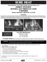
WESTERN CAMPFYRE
TM
STYLE LOGS LAYOUT SUMMARY
If you have purchased this style of log set, follow the instructions below.
Note: LOG PLACEMENT is very important for the proper operation and performance of the Real-
Fyre
®
gas log set. Please follow these instructions carefully. Refer to the photo (Fig. 19-1)
for log numbering and the overall look of the completed layout.
Step 1. Install the ember bed provided with the G46, as shown on the previous page.
Step 2. Place the bottom rear log (Log #1 in the photo) on the back of the grate so that the bark faces
to the front. The two fl at indentations and “V” notch will be face up.
Step 3. Place the left and right logs (Logs #2 & #3) so they rest on the fl at indentations on the rear log
(Log #1) and on the ends of the grate front bar leg. You may need to adjust slightly to secure
in position.
Step 4. Place top Log #4 resting with the pointed end fi tting in the “V” notch on the rear log (Log #1).
The notch on the other end of Log #4 rests against the second right-side outer grate fi nger
(check photo).
Step 5. Place top Log #5 with the “Y” end resting securely on the second left-side outer grate fi nger,
the opposite end resting on Log #4 (check photo).
Step 6. Place top Log #6 resting in the cutout on right Log #3, with its opposite resting on Log #4 (check
photo).
Step 7. Place top Log #7 (the shortest log) on the fi replace bottom, resting against the front middle
grate fi nger (check photo).
Step 8. Place top Log #8 so it rests on Log #4 and on Log #3 (check photo).
Step 9. Place top Log #9 (the round log) so it rests against the right front leg and between the two
right-side outer grate fi ngers (check photo).
1. MWCFL-18BR Rear log
2. MWCFL-18L Left log
3. MWCFL-18R Right log
4. MWCFL-13T Top log
5. MWCFL-13TY Top log
6. MWCFL-10TY Top log
7. MWCFL-8T1 Top log
8. MWCFL-11T Top log
9. MWCFL-5T Top log
ITEMS
Fig. 19-1
WESTERN CAMPFYRE
TM
LOG PLACEMENT
1
2
5
4
7
6
8
3
9

LIGHTING INSTRUCTIONS - MANUAL PILOT VALVE
The Real-Fyre
®
burner system has a pilot that can be lit by hand using a match or lighter. When lighting the pilot, follow these
instructions exactly.
BEFORE LIGHTING, smell all around the burner area for gas. Be sure to smell next to the fl oor, as some gas is heavier than
air and will settle on the fl oor. IF YOU SMELL GAS, FOLLOW THE INSTRUCTIONS ON P. 1.
Use only your hand to push in or turn the gas control knob. Never use tools. If the knob will not push in or turn by hand, don't
try to repair it. Call a qualifi ed professional service technician. Force or attempted repair may result in fi re or explosion.
WARNING
If you do not follow these instructions exactly, a fi re or explosion may result, causing property
damage, personal injury, or loss of life.
Do not use this appliance if any part has been underwater. Immediately call for a qualifi ed professional service technician to
inspect the appliance and to replace any part of the control system and any gas control that has been underwater.
FOR YOUR SAFETY, READ BEFORE LIGHTING
LIGHTING THE PILOT
1. If the burner control valve knob is not in the OFF
position, push in the gas control handle slightly
and turn clockwise
to OFF (Fig. 21-1).
Refer to the PARTS LIST for the location of the
burner control valve knob.
Note: The burner control knob cannot be turned
from PILOT to OFF unless the handle is
pushed in slightly. Do not force.
Wait fi ve minutes to clear out any gas. If you then
smell gas, STOP! Notify your gas supplier or the
fi re department immediately. If you don’t smell gas,
go on to step 2.
2. Turn the burner control knob counter-clockwise
to PILOT (Fig. 21-1). Push the control
handle all the way in and hold it. Hold a long
fi replace match or lighter near the thermocouple
to light the pilot. Continue to hold the control
knob for approximately 30 seconds after the
pilot is lit to allow the thermocouple to detect
the pilot fl ame, then release the knob. The pilot
will remain lit.
• If the pilot will not light, repeat steps 1 and 2.
• If the pilot will not stay lit after several tries, turn
the gas control handle to OFF and call your
service technician or gas supplier.
IGNITING THE MAIN BURNER
1. Make sure the pilot is burning.
2. Turn the gas control handle counterclockwise
to ON (Fig. 21-1) to ignite the burner. The
burner will ignite.
Note: Periodically check the pilot fl ame for the
proper fl ame pattern (
Fig. 21-1).
MAKE SURE THE THERMOCOUPLE AND PILOT
ASSEMBLY ARE IN CORRECT ALIGNMENT WITH
EACH OTHER (
Fig. 21-1).
TURNING OFF THE MAIN BURNER
1. From the ON position, turn the control knob
clockwise
to the PILOT position. The burner
will extinguish, and the pilot will remain lit.
EXTINGUISHING THE PILOT
1. If complete shutdown is desired, from the PILOT
position, push in the control knob slightly and
turn clockwise
to the OFF position. Do not
force the knob. This will require the pilot to be
relit before using the burner again.
21
1. Turn the knob
clockwise to
OFF
only
when complete
shutdown is
desired.
Fig. 21-1
1. Lighting -Turn the burner control knob
to OFF
and wait 5 minutes before
lighting.
2. Turn knob
counterclockwise
to PILOT position. With
match ready, press
knob in and hold for 60
seconds while lighting
pilot.
3. Turn the knob
counterclockwise
to ON to light the
burner.
PILO T
ON
OFF
OFF
ON
PILOT
OFF
ON
PILOT
OFF
ON
PILOT
Thermocouple
The Real-Fyre
®
burner system has a pilot that can be lit using the built-in piezo ignitor switch on the burner, or by hand using
a match or long-necked lighter. When lighting the pilot, follow these instructions exactly.
2. Turn the burner control knob counterclockwise
to PILOT (Fig. 21-1). Push the control
handle all the way in and hold it. Push in the
piezo ignitor button several times until the pilot
lights. Continue to hold the control knob for
approximately 60 seconds after the pilot is lit
to allow the thermocouple to detect the pilot
fl ame, then release the knob. The pilot will
remain lit.

ADJUSTING THE PILOT
a. The pilot fl ame should encircle the generator tip,
and is preset at the factory (Fig. 23-2).
b. If adjustment is necessary (Fig.23-1), turn the gas
adjustment screw counterclockwise
to increase
the pilot fl ame, or clockwise
to decrease the
pilot fl ame.
MAINTENANCE
Your pan burner is equipped with a safety pilot that will
shut off the gas supply in the event that the pilot is not
functioning properly. Make sure the pilot is adjusted
properly and that the generator spade clips are tightly
connected to the terminal screws on the valve. If the
pilot will not stay lit, call your local gas utility or gas
supplier.
A periodic check of the following should be performed
at least annually by a qualifi ed professional service
representative:
1. Valves and toggle switch control for proper
operation.
2. Flue system for rust, damage, or leaks.
3. Damper operation.
4. Orifi ces for dirt or other foreign matter.
5. Visual check on the burner.
If this unit was shipped with a remote, or if a remote
system was installed later, read and follow the
separate remote instructions to operate the burner
remotely.
WARNING
If you do not follow these instructions exactly, a fi re or explosion may result, causing property
damage, personal injury, or loss of life.
Do not use this appliance if any part has been underwater. Immediately call for a qualifi ed professional service technician
to inspect the appliance and to replace any part of the control system and any gas control that has been underwater.
FOR YOUR SAFETY, READ BEFORE LIGHTING
LIGHTING THE PILOT
To read the safety valve control knob (Fig. 23-1),
read the marking nearest the teardrop-shaped metal
pointer.
1. If the safety valve control knob is in the PILOT
position, push in slightly on the knob and rotate it
clockwise
to the OFF position.
2. Release knob and wait fi ve minutes.
3. Turn safety valve knob counterclockwise to the
PILOT position. (Only the pilot gas will fl ow when
the knob is pushed in.)
4. Place a long match or a butane lighter at the pilot
burner, and at the same time, push the safety valve
knob fully in. The pilot will light.
5. Hold the safety valve knob in for approximately 60
seconds before releasing.
6. If the pilot does not stay lit, turn the safety valve
knob clockwise
to the full OFF position. Wait fi ve
minutes, then repeat steps 3 through 5.
IGNITING THE MAIN BURNER
With the pilot lit, turn the safety valve knob counterclockwise
to the ON position. Switch the toggle switch control
to the ON position, and the burner will light.
Refer to the
PARTS LIST for the toggle switch location.
SHUTTING OFF THE MAIN BURNER
Switch the toggle switch control to the OFF position. The
pilot will remain lit.
SHUTTING OFF THE PILOT
Be sure the toggle switch control is OFF and depress
and turn the safety valve knob
clockwise to the OFF
position.
Fig. 23-1
Wiring harness
Toggle switch
Pilot screw
Pilot gas
port
control
knob
Safety
valve
IN
TH
TP
TH
TP
IN
OUT
23
LIGHTING INSTRUCTIONS - SERIES 11 VALVE
The Real-Fyre
®
burner system has a pilot that can be lit by hand using - match or lighter. When lighting the pilot, follow
these instructions exactly.
BEFORE LIGHTING, smell all around the burner area for gas. Be sure to smell next to the fl oor, as some gas is heavier than
air and will settle on the fl oor. IF YOU SMELL GAS, FOLLOW THE INSTRUCTIONS ON P. 1.
Use only your hand to push in or turn the gas control knob. Never use tools. If the knob will not push in or turn by hand, don't
try to repair it. Call a qualifi ed professional service technician. Force or attempted repair may result in fi re or explosion.
Generator
Pilot
Note: Pilot fl ame should encircle top of the generator
Fig. 23-2 Lighting the pilot
The Real-Fyre
®
burner system has a pilot that can be lit by using the built-in piezo ignitor switch on the burner, or by hand
using a match or long-necked lighter. When lighting the pilot, follow these instructions exactly.
4. Push and hold the safety valve knob fully in and
push in the piezo ignitor button several times until
the pilot lights.
Fig. 23-1
Wiring harness
Toggle switch
Pilot screw
Pilot gas
port
control
knob
Safety
valve
IN
TH
TP
TH
TP
IN
OUT
Generator
Pilot
Electrode

25
* We recommend that before you install your log set, you familiarize yourself with the control valve layout. This will help
you to be confi dent operating the log set when fully installed.
WARNING
If you do not follow these instructions exactly, a fi re or explosion may result, causing property
damage, personal injury, or loss of life.
TO LIGHT THE PILOT AND MAIN BURNER
1. STOP! Read the safety information above.
2. Tur n OFF any electrical appliance (such as the Peterson warm air circulator system) if used with the log set.
3. Place the switch (marked I = IGNITE; O = OFF,
Fig. 25-1) in the OFF position.
4. Wait fi ve (5) minutes to clear out any gas. If you then smell gas, STOP! Follow the instructions on page 1.
5. Press the switch on top of the pine cone to the I position (see
Fig. 25-2). There will be a rapid series of
sparks at the pilot (cobra) head. These sparks cease when the pilot fl ame is lit and stable. When the pilot
becomes stable, the electronic valve will open and light the main burner.
CAUTION: If the gas set does not ignite within 20 seconds, stop, wait 5 minutes, and then repeat TO LIGHT
THE PILOT AND MAIN BURNER.
LIGHTING INSTRUCTIONS - 01 VALVE
THIS UNIT (G46-01) HAS A NON-STANDING PILOT.
TO TURN OFF THE G46-01 REMOTE GAS LOG SET
1. Press the switch on top of the pine cone to the O position (O = OFF,
Fig. 25-3). The gas fl ow will cease,
and all fl ames (main burner and pilot) will go out.
If this unit was shipped with a remote, or if a remote system was installed later, read and follow the
separate remote instructions to operate the burner remotely.
Pine cone switch
Fig. 25-1
Fig. 25-2
Fig. 25-3
Pine cone switch in
ON position
Pine cone switch in
OFF position
FOR YOUR SAFETY, READ BEFORE LIGHTING
The Real-Fyre
®
G46 Series gas log set has a pilot that can be lit by hand using the piezo ignitor. When lighting
the pilot, follow these instructions exactly.
BEFORE LIGHTING, smell all around the gas log set area for gas. Be sure to smell next to the fl oor as some gas is
heavier than air and will settle on the fl oor. IF YOU SMELL GAS, FOLLOW THE INSTRUCTIONS ON PAGE 1.
Use only your hand to push in or turn the gas control knob. Never use tools. If the knob will not push in or turn by
hand, don't try to repair it. Call a qualifi ed professional service technician. Force or attempted repair may result in
fi re or explosion.
/