KitchenAid KODC304EBL Owner's manual

Category
Cookers
Type
Owner's manual
INSTALLATION INSTRUCTIONS
24" (61.0 CM) ELECTRIC SINGLE AND DOUBLE
BUILT-IN OVEN
INSTRUCTIONS D’INSTALLATION
FOUR ENCASTRÉ SIMPLE ET DOUBLE
ÉLECTRIQUE DE 24" (61,0 CM)
W10758285A
BUILT-IN OVEN SAFETY .......................................................... 1
INSTALLATION REQUIREMENTS .......................................... 2
Tools and Parts .................................................................... 2
Location Requirements ....................................................... 2
Electrical Requirements ....................................................... 4
INSTALLATION INSTRUCTIONS ........................................... 4
Prepare Built-In Oven .......................................................... 4
Remove Oven Door(s) ......................................................... 4
Make Electrical Connection ................................................. 5
Install Oven ........................................................................... 6
Complete Installation ........................................................... 7
Remove Oven Trim (if necessary) ........................................ 7
SÉCURITÉ DU FOUR ENCASTRÉ ........................................ 8
EXIGENCES D’INSTALLATION ............................................. 8
Outillage et pièces ............................................................... 8
Exigences d’emplacement .................................................. 8
Spécications électriques .................................................. 10
INSTRUCTIONS D’INSTALLATION. .................................... 11
Préparation du four encastré ............................................. 11
Retirer le(s) porte(s) du four(s) ........................................... 11
Raccordement électrique ................................................... 11
Installation du four ............................................................. 12
Achever l’installation .......................................................... 14
Dépose des garnitures du four (au besoin) ....................... 14
Table of Contents/Table des matières
IMPORTANT:
Save for local electrical inspector’s use.
IMPORTANT :
À conserver pour consultation par l’inspecteur local des installations électriques.
BUILT-IN OVEN SAFETY
2
INSTALLATION REQUIREMENTS
Tools and Parts
Gather the required tools and parts before starting installation.
Read and follow the instructions provided with any tools listed
here.
Tools Needed
Phillips screwdriver
Measuring tape
Level
Hand or electric drill (for
wall cabinet installations)
1" (25 mm) drill bit (for wall
cabinet installations)
Parts Needed
UL-listed or CSA-approved conduit connector
UL-listed wire connectors
Parts Supplied
Four# 8-14 x 1" screws
Right and left side trim
Bottom vent (supplied on some models)
Bottom vent trim
Two # 8-18 x ³⁄8" screws – bottom vent
Check local codes. Check existing electrical supply.
See “Electrical Requirements.”
It is recommended that all electrical connections be made
by a licensed, qualified electrical installer.
Product Dimensions – Single Oven
Location Requirements
IMPORTANT: Observe all governing codes and ordinances.
Cabinet opening dimensions that are shown must be used.
Given dimensions provide minimum clearance with oven.
Recessed installation area must provide complete
enclosure around the recessed portion of the oven.
Grounded electrical supply is required. See “Electrical
Requirements” section.
Electrical supply junction box should be located 3"
(7.6 cm) maximum below the support surface when the
oven is installed in a wall cabinet. A 1" (2.5 cm) minimum
diameter hole should have been drilled in right rear or the
left rear corner of the support surface to pass the appliance
cable through to the junction box.
NOTE: For undercounter installation, it is recommended
that the junction box be located in the adjacent right or
left cabinet. If you are installing the junction box on rear
wall behind oven, the junction box must be recessed and
located in the upper or lower right or left corner of the
cabinet; otherwise, the oven will not t into the cabinet
opening.
Oven support surface must be solid, level, and ush with
bottom of cabinet cutout. Floor must be able to support
a single oven weight of 140 lbs (63.5 kg) or a double oven
weight of 245 lbs (111.1 kg).
Undercounter Installation (with cooktop installed above):
Ovens approved for this type of installation have an approval
label located on the top of the oven. Refer to undercounter
installation instructions for cutout dimensions and approved
oven cooktop combinations (separate sheet).
Cabinet Dimensions – Single Oven
Single Oven Undercounter (without cooktop installed above)
A. 22³⁄8" (56.8 cm) max. recessed width
B. 29" (73.7 cm) max. overall height
C. 23³⁄4" (60.3 cm) overall width
D. 23" (58.4 cm) max. recessed depth
E. 27¹⁄2" (69.9 cm) recessed height
A. 24" (61 cm) min. cabinet width
B. 1¹⁄2" (3.8 cm) min. top of cutout
to underside of countertop
C. 5¹⁄4" (13.3 cm) bottom of cutout to floor
D. 22
5
8" (57.5 cm) cutout width
E. 27³⁄4" (70.5 cm) min. cutout height
A
B
C
D
E
A
B
C
D
E
3
Single Oven Installed in Cabinet
A. 24" (61 cm) min. cabinet width
B. 1" (2.5 cm) top of cutout to bottom
of upper cabinet door
C. 32" (81.3 cm) bottom of cutout
to floor
D. 22
5
8" (57.5 cm) cutout width
E. 1¹⁄2" (3.8 cm) min. bottom of cutout
to top of cabinet door
F. 27³⁄4" (70.5 cm) min. cutout height
Product Dimensions – Double Oven
A. 22³⁄8" (56.8 cm) max. recessed width
B. 51" (129.5 cm) max. overall height
C. 23³⁄4" (60.3 cm) overall width
D. 23" (58.4 cm) max. recessed depth
E. 49¹⁄2" (125.7 cm) recessed height
Cabinet Dimensions – Double Oven
Double Oven Installed in Cabinet
A. 24" (61 cm) min. cabinet width
B. 1" (2.5 cm) top of cutout to bottom of upper
cabinet door
C. 14³⁄4" (37.5 cm) bottom of cutout to floor
D. 22
5
8" (57.5 cm) cutout width
E. 1¹⁄2" (3.8 cm) min. bottom of cutout to top
of cabinet door
F. 49³⁄4" (126.4 cm) min. cutout height
Cabinet Side View – Double or Single Oven
A. 23¹⁄4" (59.1 cm) min. cutout depth
B. 23" (58.4 cm) recessed oven depth
C. Oven front
D. Recessed oven
E. Cabinet
A
B
D
E
C
A
B
C
D
E
F
A
B
C
D
E
F
A
B
C
D
E
4
If the house has aluminum wiring, follow the procedure
below:
1. Connect a section of solid copper wire to the pigtail
leads.
2. Connect the aluminum wiring to the added section
of copper wire using special connectors and/or tools
designed and UL listed for joining copper to aluminum.
Follow the electrical connector manufacturer’s
recommended procedure. Aluminum/copper connection
must conform with local codes and industry-accepted
wiring practices.
INSTALLATION
INSTRUCTIONS
Prepare Built-In Oven
1. Decide on the nal location for the oven. Locate existing
wiring to avoid drilling into or severing wiring during
installation.
2. To avoid oor damage, set the oven onto cardboard prior
to installation. Do not use handle or any portion of the front
frame for lifting.
On models with shipping feet attached:
To avoid product damage, do not remove the shipping feet
at the front lower corners of the oven. The shipping feet will
protect the lower oven trim until the oven is inserted into
cabinet.
3. Remove the shipping materials and tape from the oven.
4. Remove the hardware package from inside the bag
containing literature.
5. Remove and set aside racks and other parts from inside
the oven.
6. Move the oven and cardboard close to the oven’s nal
location.
Electrical Requirements
If codes permit and a separate ground wire is used, it is
recommended that a qualied electrical installer determine that
the ground path and wire gauge are in accordance with local
codes.
Check with a qualied electrical installer if you are not sure the
oven is properly grounded.
This oven must be connected to a grounded metal, permanent
wiring system.
Be sure that the electrical connection and wire size are
adequate and in conformance with the National Electrical Code,
ANSI/NFPA 70 – latest edition or CSA Standards C22.1-94,
Canadian Electrical Code, Part 1 and C22.2 No. O-M91 – latest
edition, and all local codes and ordinances.
A copy of the above code standards can be obtained from:
National Fire Protection Association
1 Batterymarch Park
Quincy, MA 02169-7471
CSA International
8501 East Pleasant Valley Road
Cleveland, OH 44131-5575
Electrical Connection
To properly install your oven, you must determine the type
of electrical connection you will be using and follow the
instructions provided for it here.
Oven must be connected to the proper electrical voltage
and frequency as specied on the model/serial number
rating plate. The model/serial number rating plate is located
on the right mounting rail. See the following illustration.
Single oven
A. Model/serial/rating plate
Models rated from 7.3 to 9.6 kW at 240 volts (5.5 to
7.2 kW at 208 volts) require a separate 40-amp circuit.
Models rated at 7.2 kW and below at 240 volts (5.4 kW
and below at 208 volts) require a separate 30-amp circuit.
A time-delay fuse or circuit breaker is recommended.
Connect directly to the fused disconnect (or circuit breaker
box) through exible, armored, or nonmetallic sheathed,
copper cable (with grounding wire). See “Make Electrical
Connection” section.
Flexible cable from the oven should be connected directly
to the junction box.
Fuse both sides of the line.
Do not cut the conduit. The length of conduit provided
is for serviceability of the oven.
A UL-listed or CSA-approved conduit connector must
be provided.
Double oven
A. Model/serial/rating plate
A
A
WARNING
Excessive Weight Hazard
Use two or more people to move and install oven.
Failure to do so can result in back or other injury.
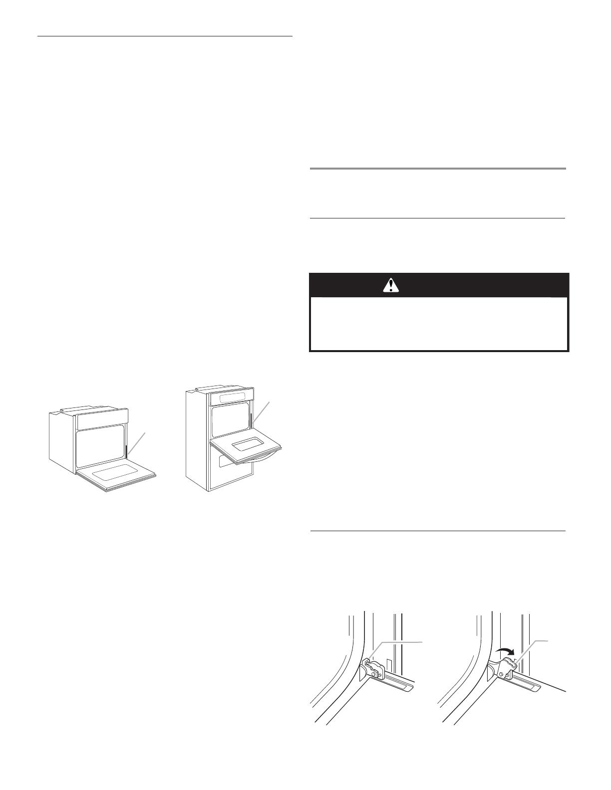
Remove Oven Door(s)
IMPORTANT: Use both hands to remove oven doors.
1. Open the oven door.
2. Locate the oven door latches in both corners of the oven
door, and rotate the latches forward to the unlocked
position.
A
B
A. Oven door latch in locked
position
A. Oven door latch in unlocked
position
5
Make Electrical Connection
The oven is manufactured with a neutral (white) power supply
wire and a cabinet-connected green (or bare) ground wire
twisted together.
1. Disconnect power.
2. Feed the exible conduit from the oven through the opening
in the cabinet.
3. Remove junction box cover if it is present.
4. Install a UL-listed or CSA-approved conduit connector
to the junction box.
5. Route the exible conduit from the oven to the junction box
through a UL-listed or CSA-approved conduit connector.
6. Tighten screws on conduit connector.
7. See “Electrical Connection Options Chart” to complete
installation for your type of electrical connection.
A. UL-listed or CSA-approved conduit connector
WARNING
Electrical Shock Hazard
Disconnect power before servicing.
Use 8 gauge solid copper wire.
Electrically ground oven.
Failure to follow these instructions can result in death,
fire, or electrical shock.
A
Electrical Connection Options Chart
If your home has: Go to section:
4-wire
½"
(1.3 cm)
4-Wire Cable from Home
Power Supply
3-wire
½"
(1.3 cm)
3-Wire Cable from Home
Power Supply
4-Wire Cable from Home Power Supply
IMPORTANT: Use the 4-wire cable from home power supply
in the U.S. where local codes do not allow grounding through
neutral, New Branch circuit installations (1996 NEC), mobile
homes and recreational vehicles, new construction and in
Canada.
A. Cable from home power supply
B. Black wires
C. Red wires
D. 4-wire exible cable from oven
E. Junction box
F. White wires
G. UL-listed wire connectors
H. Green (or bare) ground wires
I. UL-listed or CSA-approved
conduit connector
1. Connect the 2 black wires (B) together using a UL-listed wire
connector.
2. Connect the 2 red wires (C) together using a UL-listed wire
connector.
3. Untwist white wire from green (or bare) ground wire coming
from the oven.
4. Connect the 2 white wires (F) together using a UL-listed wire
connector.
5. Connect the green (or bare) ground wire (H) from the oven
cable to the green (or bare) ground wire (in the junction box)
using a UL-listed wire connector.
6. Install junction box cover.
A
D
F
H
B
C
E
G
I
3. Grasp the edges of the oven door with both hands and close
the oven door until it will no longer close. Lift and pull oven
door toward you and remove. Set the oven door aside on
a covered work surface.
6
Install Oven
2. Push against seal area of front frame to push oven
into cabinet.
3. Push oven completely into cabinet and center oven
into cabinet cutout.
4. Securely fasten oven to cabinet using the # 8-14 x 1" screws
(2 for single oven, 4 for double oven) provided. Insert the
screws through holes in mounting rails. Do not overtighten
screws.
3-Wire Cable from Home Power Supply – U.S. Only
IMPORTANT: Use the 3-wire cable from home power supply
where local codes permit a 3-wire connection.
A. Cable from home power supply
B. Junction box
C. Black wires
D. White wires
E. Green (or bare) ground wire
(from oven)
F. 4-wire flexible cable from
oven
G. Red wires
H. UL-listed wire connectors
I. UL-listed or CSA-approved
conduit connector
1. Connect the 2 black wires (C) together using a UL-listed wire
connector.
2. Connect the 2 white wires (D) and the green (or bare) ground
wire (of the oven cable) using a UL-listed wire connector.
3. Connect the 2 red wires (G) together using a UL-listed wire
connector.
4. Install junction box cover.
B
H
G
I
NOTE: Remove side and vent trims taped to oven before
installing.
1. Using 2 or more people, lift oven partially into cabinet
cutout. Use the oven opening as an area to grip.
NOTE: Push against seal area of oven front frame when
pushing oven into cabinet. Do not push against outside
edges.
A
A. Shipping foot
A
A. # 8–14 x 1" screws
5. See the following instructions to install.
Insert the vent tabs (B) into slots (A) in the oven frame.
With one # 8-18 x ³⁄8" screw (C) for each side of the vent,
fasten vent securely to the oven.
A
B
C
D
A. Oven frame slot
B. Vent tab
C. # 8-18 x ³⁄8" screw
D. Oven vent
7
4. When oven has been on for 5 minutes, feel for heat.
If you do not feel heat or if an “F” followed by a number
appears in the display, turn off the oven and contact
a qualied technician.
5. Press CANCEL.
Check Operation of Double Oven
1. Turn power on. “PF” should appear in the display.
2. Press UPPER OVEN or LOWER OVEN to select the oven
you are testing.
3. Repeat “Check Operation of Single Oven” steps 2–5.
To set the clock and other oven functions, refer to the Use
and Care Guide.
If you need Assistance or Service:
Please reference the “Assistance or Service” section of the
Use and Care Guide or contact the dealer from whom you
purchased your built-in oven.
6. Slide top end of each trim piece upward onto oven
side rails.
7. Push each trim piece into place at bottom of trim.
A
A. Push trim into place and replace screw.
8. Use screws to attach each trim piece to oven.
9. Replace oven racks.
10. Replace oven door by inserting ends of hinges into hinge
slots in the oven frame.
11. Push hinges in as far as they will go and open the oven
door. You should feel the oven door drop into place.
12. Rotate both hinge latches back to the locked position.
13. Check that door is free to open and close. If it is not, repeat
the removal and installation procedures. See “Remove
Oven Trim” section.
14. Repeat for lower oven door.
15. Reconnect power.
16. Display panel will light briey, and “PF” should appear
in the display.
17. If display panel does not light, please reference the
“Assistance or Service” section of the Use and Care Guide
or contact the dealer from whom you purchased your oven.
A. Remove trim screw and pull out.
A
Remove Oven Trim (if necessary)
1. Remove bottom screw on each side of the oven trim.
2. Grasp the bottom end of trim and pull away from oven.
3. Slide top end of trim downward to remove trim from oven.
Set trim aside.
Complete Installation
1. Check that all parts are now installed. If there is an extra
part, go back through the steps to see which step was
skipped.
2. Check that you have all of your tools.
3. Dispose of/recycle all packaging materials.
4. For oven use and cleaning, read the Use and Care Guide.
Check Operation of Single Oven
1. Turn power on. “PF” should appear in the display.
2. Press BROIL. “BROIL” will appear in the display.
3. Press START. Make sure the oven door is closed
and the “ON” light is shown in the display.
If oven(s) does not operate, check the following:
Household fuse is intact and tight or circuit breaker
has not tripped.
Electrical supply is connected.
See “Troubleshooting” section in the Use and Care
Guide.
  • Page 1 1
  • Page 2 2
  • Page 3 3
  • Page 4 4
  • Page 5 5
  • Page 6 6
  • Page 7 7
  • Page 8 8
  • Page 9 9
  • Page 10 10
  • Page 11 11
  • Page 12 12
  • Page 13 13
  • Page 14 14
  • Page 15 15
  • Page 16 16

KitchenAid KODC304EBL Owner's manual

Category
Cookers
Type
Owner's manual

Ask a question and I''ll find the answer in the document

Finding information in a document is now easier with AI

in other languages