
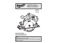
18V CIRCULAR SAW
SCIE CIRCULAIRE DE 18 V
SIERRA CIRCULAR DE 18V
Cat. No.
No de cat.
2630-20
OPERATOR'S MANUAL
MANUEL de L'UTILISATEUR
MANUAL del OPERADOR
TO REDUCE THE RISK OF INJURY, USER MUST READ AND UNDERSTAND OPERATOR'S
MANUAL.
AFIN DE RÉDUIRE LE RISQUE DE BLESSURES, L'UTILISATEUR DOIT LIRE ET BIEN
COMPRENDRE LE MANUEL DE L'UTILISATEUR.
PARA REDUCIR EL RIESGO DE LESIONES, EL USUARIO DEBE LEER Y ENTENDER EL
MANUAL DEL OPERADOR.

2
3
If the blade becomes twisted or misaligned in
the cut, the teeth at the back edge of the blade
can dig into the top surface of the wood causing
the blade to climb out of the kerf and jump back
toward operator.
KICKBACK is the result of saw misuse and/or
incorrect operating procedures or conditions and
can be avoided by taking proper precautions as
given below:
• Maintain a fi rm grip with both hands on the
saw and position your arms to resist kickback
forces. Position your body to either side of the
blade, but not in line with the blade. Kickback
could cause the saw to jumb backwards, but kick-
back forces can be controlled by the operator, if
proper precautions are taken.
• When blade is binding, or when interrupting
a cut for any reason, release the trigger and
hold the saw motionless in the material until
the blade comes to a complete stop. Never
attempt to remove the saw from the work or
pull the saw backward while the blade is in
motion or kickback may occur. Investigate and
take corrective actions to eliminate the cause of
blade binding.
• When restarting a saw in the workpiece, center
the saw blade in the kerf and check that saw
teeth are not engaged into the material. If saw
blade is binding, it may walk up or kickback from
the workpiece as the saw is restarted.
• Support large panels to minimise the risk of
blade pinching and kickback. Large panels tend
to sag under their own weight. Supports must be
placed under the panel on both sides, near the
line of cut and near the edge of the panel.
• Do not use dull or damaged blade. Unsharp-
ened or improperly set blades produce narrow
kerf causing excessive friction, blade binding and
kickback.
• Blade depth and bevel adjusting locking levers
must be tight and secure before making cut. If
blade adjustment shifts while cutting, it may cause
binding and kickback.
• Use extra caution when making a "plunge cut"
(or pocket cut) into existing walls or other blind
areas. The protruding blade may cut objects that
can cause kickback.
• Check lower guard for proper closing before
each use. Do not operate saw if lower guard
does not move freely and close instantly. Never
clamp or tie the lower guard into the open posi-
tion. If saw is accidentally dropped, lower guard
may be bent. Raise the lower guard with the lower
guard lever and make sure it moves freely and
does not touch the blade or any other part, in all
angles and depths of cut.
• Check the operation of the lower guard spring.
If the guard and the spring are not operating
properly, they must be serviced before use.
Lower guard may operate sluggishly due to
damaged parts, gummy deposits, or a buildup of
debris.
• Lower guard should be retracted manually only
for special cuts such as "plunge cuts" and
"compound cuts". Raise lower guard by lower
PERSONAL SAFETY
GENERAL POWER TOOL SAFETY WARNINGS
WORK AREA SAFETY
ELECTRICAL SAFETY
• Keep work area clean and well lit. Cluttered or
dark areas invite accidents.
• Do not operate power tools in explosive atmo-
spheres, such as in the presence of fl ammable
liquids, gases or dust. Power tools create sparks
which may ignite the dust or fumes.
• Keep children and bystanders away while
operating a power tool. Distractions can cause
you to lose control.
• Power tool plugs must match the outlet. Never
modify the plug in any way. Do not use any
adapter plugs with earthed (grounded) power
tools. Unmodifi ed plugs and matching outlets will
reduce risk of electric shock.
• Avoid body contact with earthed or grounded
surfaces such as pipes, radiators, ranges and
refrigerators. There is an increased risk of electric
shock if your body is earthed or grounded.
• Do not expose power tools to rain or wet condi-
tions. Water entering a power tool will increase
the risk of electric shock.
• Do not abuse the cord. Never use the cord for
carrying, pulling or unplugging the power tool.
Keep cord away from heat, oil, sharp edges
or moving parts. Damaged or entangled cords
increase the risk of electric shock.
• When operating a power tool outdoors, use an
extension cord suitable for outdoor use. Use
of a cord suitable for outdoor use reduces the risk
of electric shock.
• If operating a power tool in a damp location
is unavoidable, use a residual current device
(RCD) protected supply. Use of an RCD reduces
the risk of electric shock.
• Remove any adjusting key or wrench before
turning the power tool on. A wrench or a key left
attached to a rotating part of the power tool may
result in personal injury.
• Do not overreach. Keep proper footing and
balance at all times. This enables better control
of the power tool in unexpected situations.
• Dress properly. Do not wear loose clothing or
jewellery. Keep your hair, clothing and gloves
away from moving parts. Loose clothes, jewel-
lery or long hair can be caught in moving parts.
• If devices are provided for the connection of
dust extraction and collection facilities, ensure
these are connected and properly used. Use of
dust collection can reduce dust-related hazards.
POWER TOOL USE AND CARE
• Do not force the power tool. Use the correct
power tool for your application. The correct
power tool will do the job better and safer at the
rate for which it was designed.
• Do not use the power tool if the switch does not
turn it on and off. Any power tool that cannot be
controlled with the switch is dangerous and must
be repaired.
• Disconnect the plug from the power source
and/or the battery pack from the power tool
before making any adjustments, changing
accessories, or storing power tools. Such
preventive safety measures reduce the risk of
starting the power tool accidentally.
• Store idle power tools out of the reach of chil-
dren and do not allow persons unfamiliar with
the power tool or these instructions to operate
the power tool. Power tools are dangerous in the
hands of untrained users.
• Maintain power tools. Check for misalignment
or binding of moving parts, breakage of parts
and any other condition that may affect the
power tool’s operation. If damaged, have the
power tool repaired before use. Many accidents
are caused by poorly maintained power tools.
• Keep cutting tools sharp and clean. Properly
maintained cutting tools with sharp cutting edges
are less likely to bind and are easier to control.
• Use the power tool, accessories and tool bits
etc., in accordance with these instructions,
taking into account the working conditions and
the work to be performed. Use of the power tool
for operations different from those intended could
result in a hazardous situation.
• Stay alert, watch what you are doing and use
common sense when operating a power tool. Do
not use a power tool while you are tired or under
the infl uence of drugs, alcohol or medication. A
moment of inattention while operating power tools
may result in serious personal injury.
• Use personal protective equipment. Always
wear eye protection. Protective equipment such
as dust mask, non-skid safety shoes, hard hat, or
hearing protection used for appropriate conditions
will reduce personal injuries.
• Prevent unintentional starting. Ensure the
switch is in the off-position before connecting
to power source and/or battery pack, picking
up or carrying the tool. Carrying power tools with
your fi nger on the switch or energising power tools
that have the switch on invites accidents.
• Recharge only with the charger specifi ed by
the manufacturer. A charger that is suitable for
one type of battery pack may create a risk of fi re
when used with another battery pack.
BATTERY TOOL USE AND CARE
SPECIFIC SAFETY RULES
• Use power tools only with specifi cally desig-
nated battery packs. Use of any other battery
packs may create a risk of injury and fi re.
• When battery pack is not in use, keep it away
from other metal objects like paper clips,
coins, keys, nails, screws, or other small metal
objects that can make a connection from one
terminal to another. Shorting the battery termi-
nals together may cause burns or a fi re.
• Under abusive conditions, liquid may be eject-
ed from the battery; avoid contact. If contact
accidentally occurs, fl ush with water. If liquid
contacts eyes, additionally seek medical help.
Liquid ejected from the battery may cause irritation
or burns.
SERVICE
• Have your power tool serviced by a qualifi ed
repair person using only identical replacement
parts. This will ensure that the safety of the power
tool is maintained.
DANGER:
• Keep hands away from cutting area and blade.
Keep your second hand on auxiliary handle or
motor housing. If both hands are holding the saw,
they cannot be cut by the blade.
• Do not reach underneath the workpiece. The
guard cannot protect you from the blade below the
workpiece.
• Adjust the cutting depth to the thickness of
the workpiece. Less than a full tooth of the blade
teeth should be visible below the workpiece.
• NEVER hold piece being cut in your hands
or across your leg. Secure the workpiece to
a stable platform. It is important to support the
work properly to minimize body exposure, blade
binding, or loss of control.
• Hold power tool by insulated gripping surfaces
when performing an operation where the cut-
ting tool may contact hidden wiring or its own
cord. Contact with a “live” wire will also make
exposed metal parts of the tool “live” and shock
the operator.
• When ripping always use a rip fence or straight
edge guide. This improves the accuracy of cut and
reduces the chance of blade binding.
• Always use blades with correct size and shape
(diamond versus round) of arbor holes. Blades
that do not match the mounting hardware of the
saw will run eccentrically, causing loss of control.
• Never use damaged or incorrect blade wash-
ers or bolts. The blade washers and bolts were
specially designed for your saw, for optimum
performance and safety of operation.
Causes and Operator Prevention of KICK-
BACK:
KICKBACK is a sudden reaction to a pinched,
bound or misaligned saw blade, causing an un-
controlled saw to lift up and out of the workpiece
toward the operator.
When the blade is pinched or bound tightly by the
kerf closing down, the blade stalls and the motor
reaction drives the unit rapidly back toward the
operator.
WARNING READ ALL SAFETY WARNINGS AND ALL INSTRUCTIONS.
Failure to follow the warnings and instructions may result in electric shock, fi re and/or
serious injury. Save all warnings and instructions for future reference.
The term "power tool" in the warnings refers to your mains-operated (corded) power tool or
battery-operated (cordless) power tool.

4
5
guard lever and as soon as blade enters the
material, the lower guard must be released. For
all other sawing, the lower guard should operate
automatically.
• Always observe that the lower guard is cov-
ering the blade before placing saw down on
bench or fl oor. An unprotected, coasting blade
will cause the saw to walk backwards, cutting
whatever is in its path. Be aware of the time it takes
for the blade to stop after switch is released.
• Maintain labels and nameplates. These carry
important information. If unreadable or missing,
contact a MILWAUKEE service facility for a free
replacement.
• WARNING Some dust created by power sanding,
sawing, grinding, drilling, and other construction
activities contains chemicals known to cause
cancer, birth defects or other reproductive harm.
Some examples of these chemicals are:
• lead from lead-based paint
• crystalline silica from bricks and cement and other
masonry products, and
• arsenic and chromium from chemically-treated
lumber.
Your risk from these exposures varies, depending
on how often you do this type of work. To reduce
your exposure to these chemicals: work in a well
ventilated area, and work with approved safety
equipment, such as those dust masks that are spe-
cially designed to fi lter out microscopic particles.
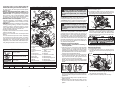
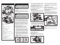
1. Front handle
2. Lock-off button
3. Trigger
4. Handle
5. Lower guard lever
6. Shoe
7. Lower guard
8. Lower guard arrow
9. Blade bolt
10. Blade fl ange
11. Blade
12. Rip fence slot
13. Sight line
14. Rip fence adjusting
knob
15. Upper guard
16. Wrench
17. Spindle lock button
18. Bevel pointer
19. Bevel adjusting knob
20. Bevel scale
21. Depth adjusting lever
Direct Current
Underwriters Laboratories, Inc.
United States and Canada
No Load Revolutions per
Minute (RPM)
Cat. No. Volts DC No Load RPM Blade Size Arbor Depth of Cut At 90° Depth of Cut at 45°
2630-20 18 3500 6-1/2” 5/8” 0 to 2-1/8" 0 to 1-9/16”
FUNCTIONAL DESCRIPTION
SYMBOLOGY
SPECIFICATIONS
ASSEMBLY
WARNING Recharge only with the
charger specifi ed for the battery. For
specifi c charging instructions, read the opera-
tor’s manual supplied with your charger and
battery.
Inserting/Removing the Battery
To remove the battery, push in the release buttons
and pull the battery pack away from the tool.
To insert the battery, slide the pack into the body of
the tool. Make sure it latches securely into place.
2
1
5
3
6
7
4
13
8
15
9
14
10
12
11
16
18
17
20
21
19
Selecting Blade
Always use sharp blades. Dull blades tend to
overload the tool and increase the chance of
KICKBACK (see "Causes and Operator Prevention
of KICKBACK"). Only use thin kerf blades with a
maximum safe operating speed greater than the no
load RPM marked on the tool's nameplate. Read
the blade manufacturer's instructions before use.
Do not use any type of abrasive cut-off wheel or
dry diamond cutting blades.
Installing and Removing Blades
1. Remove battery pack before installing or
removing blades.
2. Place the saw on a fl at surface with the blade
facing upwards. To remove the bolt from the
spindle, push in the spindle lock button. While
holding in the spindle lock button, use the wrench
provided with the tool to turn the bolt clockwise.
Remove the bolt and blade fl ange.
3. Slide the lower guard lever up to raise the lower
guard. Remove the blade from the spindle. Al-
ways clean the spindle, upper guard and lower
guard to remove any dirt and sawdust.
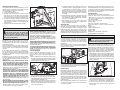
NOTE: Do not remove inner blade fl ange. Larger
diameter of inner fl ange (Fig. 1) should face the
blade.
Bolt
Outer fl ange
Inner fl ange
Spindle
Fig. 1
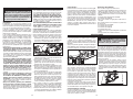
3. Raise or lower the shoe to the desired position.
Markings in 1/4" increments are located on the
inner side of the upper guard for depth setting.
For the proper depth setting, the blade should
extend no more than 1/8" to 1/4" below the mate-
rial being cut (Fig. 3).
4. Lift the depth adjusting lever up towards the
motor housing to secure the shoe position.
Adjusting Bevel Angle
1. Remove battery pack.
2. To adjust the angle of the cut, hold the saw by
the handle and loosen the bevel adjusting knob
(Fig. 4).
4. To install a blade, place the blade on the spindle
with the teeth pointing in the same direction as
the arrow on the lower guard. Release the lower
guard lever.
5. Place the blade fl ange on the spindle and hand
tighten the bolt.
6. While holding in the spindle lock button, use the
wrench to turn the bolt counterclockwise and
tighten.
1/4”
(
6 mm
)
Fig. 2
Fig. 3
WARNING Always remove battery
pack before changing or removing ac-
cessories. Only use accessories specifi cally
recommended for this tool. Others may be
hazardous.
3. Hold the front of the shoe and rotate the saw by
the handle to the desired angle as indicated by
the markings on the bevel scale.
4. Tighten the bevel adjusting knob securely.
Fig. 4
Adjusting Depth
1. Remove battery pack.
2. To adjust the depth of the cut, hold the saw by
the handle and loosen the depth adjusting lever
by pushing it down toward the shoe (Fig. 2).

6
7
• Support large panels to minimise the risk of
blade pinching and kickback. Large panels tend
to sag under their own weight. Supports must be
placed under the panel on both sides, near the
line of cut and near the edge of the panel.
• Do not use dull or damaged blade. Unsharp-
ened or improperly set blades produce narrow
kerf causing excessive friction, blade binding and
kickback.
• Blade depth and bevel adjusting locking levers
must be tight and secure before making cut. If
blade adjustment shifts while cutting, it may cause
binding and kickback.
• Use extra caution when making a "plunge cut"
(or pocket cut) into existing walls or other blind
areas. The protruding blade may cut objects that
can cause kickback.
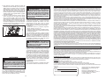
General Operation
Always clamp the workpiece securely on a saw
horse or bench. See “APPLICATIONS” for the
correct way to support your work in different situ-
ations.
1. Draw a cutting line. Place the front of the shoe on
the edge of the workpiece without making blade
contact. Hold the handle with one hand and the
front handle with the other (Fig. 6).
WARNING To reduce the risk of injury,
keep hands away from the blade and
other moving parts. Always wear safety
goggles or glasses with side shields. Use
only specifi cally recommended accessories.
Others may be hazardous.
frequently, the saw needs servicing by an autho-
rized MILWAUKEE service facility. The brake is not
a substitute for the guard, and you must always wait
for the blade to stop completely before removing
the saw from the workpiece.
Troubleshooting
If the blade does not follow a straight line:
• Teeth are dull. This is caused by hitting a hard
object such as a nail or stone, dulling teeth on
one side. The blade tends to cut to the side with
the sharpest teeth.
• Shoe is out of line or bent
• Blade is bent
• Rip fence or guide is not being used
If the blade binds, smokes or turns blue from
friction:
• Blade is dull
• Blade is on backwards
• Blade is bent
• Blade is dirty
• Workpiece is not properly supported
• Incorrect blade is being used
2. Line up the sight line with your cutting line. Posi-
tion your arms and body to resist KICKBACK.
3. To start the saw, push the lock-off button down
while pulling the trigger. Allow the motor to reach
full speed before beginning cut.
4. While cutting, keep the shoe fl at against the
workpiece and maintain a fi rm grip. Do not force
the saw through the workpiece. Forcing a saw
can cause KICKBACK.
Cutting Large Panels
Large panels and long boards sag or bend if they
are not correctly supported. If you attempt to
cut without leveling and properly supporting the
workpiece, the blade will tend to bind, causing
KICKBACK.
Support large panels. Be sure to set the depth of
the cut so that you only cut through the workpiece,
not through the supports.
Fig. 7
Fig. 6
OPERATION
APPLICATIONS
Cross-Cutting Wood
Cross-cutting is cutting across the grain. Select the
proper blade for your job. Advance the saw slowly
to avoid splintering the wood.
Ripping Wood
Ripping is cutting lengthwise with the grain. Select
the proper blade for your job. Use a rip fence for
rips 4" wide or less. To install the rip fence, slide
the bar through the rip fence slot in either side of
the shoe. The width of the cut is the distance from
the inside of the blade to the inside edge of the rip
fence. Adjust the rip fence for the desired width,
and lock the setting by tightening the rip fence
adjusting knob.
When ripping widths greater than 4", clamp or tack
1" lumber to workpiece and use the inside edge of
the shoe as a guide.
Plunge Cutting
Plunge cuts are made in the middle of the work-
piece when it can not be cut from an edge. We rec-
ommend using a Sawzall
®
reciprocating saw or jig
saw for this type of cut. However, if you must use a
circular saw to make a plunge cut, USE EXTREME
CAUTION. To maintain control of the saw during
plunge cutting, keep both hands on the saw.
1. Beginning at a corner, line up the sight line with
your cutting line. Tilt the saw forward, fi rmly fi xing
the front of the shoe on the workpiece (Fig. 8).
The blade should be just above cutting line, but
not touching it. Raise the lower guard using the
lower guard lever.
WARNING To reduce the risk of elec-
tric shock, check work area for hidden pipes
and wires before making plunge cuts.
Fig. 8
Bevel
adjustment
screw
Fig. 5
Adjusting the Blade to Shoe
The shoe has been adjusted at the factory to a 90
degree setting. Inspect the saw regularly to make
sure the blade is 90 degrees to the shoe.
1. Remove battery pack.
2. Set the bevel pointer to zero.
3. To make sure the blade is 90 degrees to the
shoe, place saw on the blade side and retract
lower guard. Place a square against the blade
and shoe to inspect the degree setting (Fig. 5).
4. To adjust the degree setting, loosen the bevel
adjusting knob. Turn the bevel adjustment screw
in or out until the blade is at a 90 degree angle
with the shoe.
5. Tighten the bevel adjusting knob securely.
Causes and Operator Prevention of KICKBACK:
KICKBACK is a sudden reaction to a pinched,
bound or misaligned saw blade, causing an un-
controlled saw to lift up and out of the workpiece
toward the operator.
When the blade is pinched or bound tightly by the
kerf closing down, the blade stalls and the motor
reaction drives the unit rapidly back toward the
operator.
If the blade becomes twisted or misaligned in
the cut, the teeth at the back edge of the blade
can dig into the top surface of the wood causing
the blade to climb out of the kerf and jump back
toward operator.
KICKBACK is the result of saw misuse and/or
incorrect operating procedures or conditions and
can be avoided by taking proper precautions as
given below:
• Maintain a fi rm grip with both hands on the
saw and position your arms to resist kickback
forces. Position your body to either side of the
blade, but not in line with the blade. Kickback
could cause the saw to jumb backwards, but kick-
back forces can be controlled by the operator, if
proper precautions are taken.
• When blade is binding, or when interrupting
a cut for any reason, release the trigger and
hold the saw motionless in the material until
the blade comes to a complete stop. Never
attempt to remove the saw from the work or
pull the saw backward while the blade is in
motion or kickback may occur. Investigate and
take corrective actions to eliminate the cause of
blade binding.
• When restarting a saw in the workpiece, center
the saw blade in the kerf and check that saw
teeth are not engaged into the material. If saw
blade is binding, it may walk up or kickback from
the workpiece as the saw is restarted.
5. If making a partial cut, restarting in mid-cut or
correcting direction, allow the blade to come to
a complete stop. To resume cutting, center the
blade in the kerf, back the saw away from cut-
ting edge a few inches, push the lock-off button
down while pulling the trigger and re-enter the
cut slowly.
6. If the saw binds and stalls, maintain a fi rm grip
and release the trigger immediately. Hold the
saw motionless in the workpiece until the blade
comes to a complete stop.
7. After fi nishing a cut, be sure the lower guard
closes and the blade comes to a complete stop
before setting the saw down.
Electric Brake
The electric brake engages when the trigger is
released, causing the blade to stop and allowing
you to proceed with your work. Generally, the saw
blade stops within two seconds. However, there
may be a delay between the time you release the
trigger and when the brake engages. Occasionally
the brake may miss completely. If the brake misses
2. To start the saw, push the lock-off button down
while pulling the trigger. Allow the motor to reach
full speed before beginning cut. Using the front
of the shoe as a hinge point, gradually lower
the back end of the saw into the workpiece.
Release the lower guard lever and grasp the
front handle.

8
9
ACCESSORIES
For a complete listing of accessories refer to your
MILWAUKEE Electric Tool catalog or go online
to www.milwaukeetool.com. To obtain a catalog,
contact your local distributor or service center.
WARNING Always remove battery
pack before changing or removing ac-
cessories. Only use accessories specifi cally
recommended for this tool. Others may be
hazardous.
Maintaining Tool
Keep your tool, battery pack and charger in good re-
pair by adopting a regular maintenance program.
After six months to one year, depending on use,
return the tool, battery pack and charger to a
MILWAUKEE service facility for:
• Lubrication
• Mechanical inspection and cleaning (gears,
spindles, bearings, housing, etc.)
• Electrical inspection (battery pack, charger,
motor)
• Testing to assure proper mechanical and
electrical operation
If the tool does not start or operate at full power
with a fully charged battery pack, clean the contacts
on the battery pack. If the tool still does not work
properly, return the tool, charger and battery pack,
to a MILWAUKEE service facility for repairs.
MAINTENANCE
Cleaning
Clean dust and debris from charger and tool vents.
Keep tool handles clean, dry and free of oil or grease.
Use only mild soap and a damp cloth to clean the
tool, battery pack and charger since certain cleaning
agents and solvents are harmful to plastics and other
insulated parts. Some of these include gasoline,
turpentine, lacquer thinner, paint thinner, chlorinated
cleaning solvents, ammonia and household deter-
gents containing ammonia. Never use fl ammable or
combustible solvents around tools.
Repairs
For repairs, return the tool, battery pack and char-
ger to the nearest service center.
WARNING To reduce the risk of per-
sonal injury and damage, never immerse your
tool, battery pack or charger in liquid or allow
a liquid to fl ow inside them.
WARNING To reduce the risk of injury,
always unplug the charger and remove
the battery pack from the charger or tool
before performing any maintenance. Never
disassemble the tool, battery pack or charger.
Contact a MILWAUKEE service facility for ALL
repairs.
TECHTRONIC INDUSTRIES' warranty is for 5 year since the original purchase date.
This warranty card covers any defect in material and workmanship on this Power Tool.
To make this warranty valid, present this warranty card, sealed/stamped by the distributor or store where you purchased the
product, to the Authorized Service Center (ASC). Or, if this card has not been sealed/stamped, present the original proof of
purchase to the ASC.
Call toll-free 1 800 832 1949 to fi nd the nearest ASC, for service, parts, accessories or components.
Procedure to make this warranty valid
Take the product to the ASC, along with the warranty card sealed/stamped by the distributor or store where you purchased the
product, and there any faulty piece or component will be replaced without cost for you. We will cover all freight costs relative
with this warranty process.
Exceptions
This warranty is not valid in the following situations:
a) When the product is used in a different manners from the end-user guide or instruction manual.
b) When the conditions of use are not normal.
c) When the product was modifi ed or repaired by people not authorized by TECHTRONIC INDUSTRIES.
Note: If cord set is damaged, it should be replaced by an Authorized Service Center to avoid electric risks.
SERVICE AND ATTENTION CENTER
Rafael Buelna No.1.
Col. Tezozomoc Mexico, Azcapotzalco D.F.
Ph. 01 800 832 1949
IMPORTED AND COMMERCIALIZED BY:
TECHTRONIC INDUSTRIES MEXICO, .S.A. DE C.V.
Av. Santa Fe 481 piso 6, Col. Curz Manca.
CP 05349, Cuajimalpa, D.F.
LIMITED WARRANTY - USA AND CANADA
LIMITED WARRANTY - MEXICO, CENTRAL AMERICA AND CARIBBEAN
Model:
Date of Purchase:
Distributor or Store Stamp:
Every MILWAUKEE power tool (including cordless product – tool, battery pack(s) - see separate & distinct CORDLESS BAT-
TERY PACK LIMITED WARRANTY statements & battery charger and Work Lights*) is warranted to the original purchaser only
to be free from defects in material and workmanship. Subject to certain exceptions, MILWAUKEE will repair or replace any part
on an electric power tool which, after examination, is determined by MILWAUKEE to be defective in material or workmanship
for a period of fi ve (5) years* after the date of purchase unless otherwise noted. Return of the power tool to a MILWAUKEE
factory Service Center location or MILWAUKEE Authorized Service Station, freight prepaid and insured, is required. A copy of
the proof of purchase should be included with the return product. This warranty does not apply to damage that MILWAUKEE
determines to be from repairs made or attempted by anyone other than MILWAUKEE authorized personnel, misuse, alterations,
abuse, normal wear and tear, lack of maintenance, or accidents.
*The warranty period for, Job Site Radios, M12™ Power Port and Trade Titan™ Industrial Work Carts is one (1) year from the
date of purchase. The warranty period for a LED Work Light and LEDUpgrade Bulb is a limited LIFETIME warranty to the original
purchaser only, if during normal use the LED bulb fails the Work Light or Upgrade Bulb will be replaced free of charge.
*This warranty does not cover Air Nailers & Stapler, Airless Paint Sprayer, Cordless Battery Packs, Gasoline Driven Portable
Power Generators, Hand Tools, Hoist – Electric, Lever & Hand Chain, M12™ Heated Jackets, Reconditioned product and Test
& Measurement products. There are separate and distinct warranties available for these products.
Warranty Registration is not necessary to obtain the applicable warranty on a MILWAUKEE power tool product. The manu-
facturing date of the product will be used to determine the warranty period if no proof of purchase is provided at the time
warranty service is requested.
ACCEPTANCE OF THE EXCLUSIVE REPAIR AND REPLACEMENT REMEDIES DESCRIBED HEREIN IS A CONDITION OF
THE CONTRACT FOR THE PURCHASE OF EVERY MILWAUKEE PRODUCT. IF YOU DO NOT AGREE TO THIS CONDITION,
YOU SHOULD NOT PURCHASE THE PRODUCT. IN NO EVENT SHALL MILWAUKEE BE LIABLE FOR ANY INCIDENTAL,
SPECIAL, CONSEQUENTIAL OR PUNITIVE DAMAGES, OR FOR ANY COSTS, ATTORNEY FEES, EXPENSES, LOSSES
OR DELAYS ALLEGED TO BE AS A CONSEQUENCE OF ANY DAMAGE TO, FAILURE OF, OR DEFECT IN ANY PRODUCT
INCLUDING, BUT NOT LIMITED TO, ANY CLAIMS FOR LOSS OF PROFITS. SOME STATES DO NOT ALLOW THE EXCLU-
SION OR LIMITATION OF INCIDENTAL OR CONSEQUENTIAL DAMAGES, SO THE ABOVE LIMITATION OR EXCLUSION
MAY NOT APPLY TO YOU. THIS WARRANTY IS EXCLUSIVE AND IN LIEU OF ALL OTHER EXPRESS WARRANTIES,
WRITTEN OR ORAL. TO THE EXTENT PERMITTED BY LAW, MILWAUKEE DISCLAIMS ANY IMPLIED WARRANTIES,
INCLUDING WITHOUT LIMITATION ANY IMPLIED WARRANTY OF MERCHANTABILITY OR FITNESS FOR A PARTICULAR
USE OR PURPOSE; TO THE EXTENT SUCH DISCLAIMER IS NOT PERMITTED BY LAW, SUCH IMPLIED WARRANTIES
ARE LIMITED TO THE DURATION OF THE APPLICABLE EXPRESS WARRANTY AS DESCRIBED ABOVE. SOME STATES
DO NOT ALLOW LIMITATIONS ON HOW LONG AN IMPLIED WARRANTY LASTS, SO THE ABOVE LIMITATION MAY NOT
APPLY TO YOU, THIS WARRANTY GIVES YOU SPECIFIC LEGAL RIGHTS, AND YOU MAY ALSO HAVE OTHER RIGHTS
WHICH VARY FROM STATE TO STATE.
This warranty applies to product sold in the U.S.A. and Canada only.
Please consult the ‘Service Center Search’ in the Parts & Service section of MILWAUKEE’s website www.milwaukeetool.com
or call 1.800.SAWDUST (1.800.729.3878) to locate your nearest MILWAUKEE factory Service Center location.
Fig. 9
3. When the shoe rests fl at against workpiece,
advance the saw to the far corner (Fig. 9). Re-
lease the trigger and allow the blade to come to
a complete stop before removing it from work-
piece. Repeat the above steps for each side of
the opening. Use a Sawzall
®
reciprocating saw,
jig saw or small hand saw to fi nish the corners
if they are not completely cut through.
Page is loading ...
Page is loading ...
Page is loading ...
Page is loading ...
Page is loading ...
Page is loading ...
Page is loading ...
Page is loading ...
Page is loading ...

28
MILWAUKEE ELECTRIC TOOL CORPORATION
13135 West Lisbon Road • Brookfi eld, Wisconsin, U.S.A. 53005
58-14-2631d3 09/10 Printed in China
960931596-01( )
UNITED STATES - MILWAUKEE Service
MILWAUKEE prides itself in producing a premium
quality product that is NOTHING BUT HEAVY DUTY
®
.
Your satisfaction with our products is very impor-
tant to us! If you encounter any problems with the
operation of this tool, or you would like to locate the
factory Service/Sales Support Branch or authorized
service station nearest you, please call...
Canada - Service MILWAUKEE
MILWAUKEE est fi er de proposer un produit de
première qualité NOTHING BUT HEAVY DUTY
®
. Votre
satisfaction est ce qui compte le plus!
En cas de problèmes d’utilisation de l’outil ou pour local-
iser le centre de service/ventes ou le centre d’entretien
le plus proche, appelez le...
416.439.4181
fax: 416.439.6210
Milwaukee Electric Tool (Canada) Ltd
755 Progress Avenue
Scarborough, Ontario M1H 2W7
Notre réseau national de distributeurs agréés se
tient à votre disposition pour fournir l’aide technique,
l’outillage et les accessoires nécessaires. Composez
le 416.439.4181 pour obtenir les noms et adresses
des revendeurs les plus proches ou bien consultez la
section «Où acheter» sur notre site web à l’adresse
www.milwaukeetool.com
MEXICO - Soporte de Servicio
MILWAUKEE
1-800-SAWDUST
(1.800.729.3878)
Monday-Friday
7:00 AM - 6:30 PM
Central Time
or visit our website at
www.milwaukeetool.com
Additionally, we have a nationwide network of
authorized Distributors ready to assist you with
your tool and accessory needs. Check your “Yellow
Pages” phone directory under “Tools-Electric” for
the names & addresses of those nearest you or see
the 'Where To Buy' section of our website.
Contact our Corporate After Sales Service
Technical Support about ...
•Technical Questions
•Service/Repair Questions
•Warranty
call: 1-800-SAWDUST
fax: 1.800.638.9582
email: [email protected]
Register your tool online at
www.milwaukeetool.com and...
• receive important notifi cations regarding
your purchase
• ensure that your tool is protected under the
warranty
• become a HEAVY DUTY club member
For service information, use the 'Service Center
Search' icon found in the 'Parts & Service' section.
CENTRO DE ATENCIÓN A CLIENTES
Rafael Buelna No. 1, Col Tezozomoc,
Delegación Azcapotzalco, México, D.F.
Telefono sin costo 01 800 832 1949
e-mail: [email protected]
Adicionalmente, tenemos una red nacional de distribui-
dores autorizados listos para ayudarle con su herramienta
y sus accesorios. Por favor, llame al 01 800 832 1949 para
obtener los nombres y direcciones de los más cercanos
a usted, o consulte la sección ‘Where to buy’ (Dónde
comprar) de nuestro sitio web en
www.ttigroupmexico.com
Registre su herramienta en línea, en
www.ttigroupmexico.com y...
• reciba importantes avisos sobre su compra
• asegúrese de que su herramienta esté
protegida por la garantía
• conviértase en integrante de Heavy Duty
-
 1
1
-
 2
2
-
 3
3
-
 4
4
-
 5
5
-
 6
6
-
 7
7
-
 8
8
-
 9
9
-
 10
10
-
 11
11
-
 12
12
-
 13
13
-
 14
14
-
 15
15


Ask a question and I''ll find the answer in the document
Finding information in a document is now easier with AI
in other languages
- français: Milwaukee 2630-20 Manuel utilisateur
- español: Milwaukee 2630-20 Manual de usuario
Related papers
-
Milwaukee 2630-20 User manual
-
-
NEC V28 0730-20 User manual
-
-
-
Milwaukee V28 0730-20 User manual
-
-
-
-
Other documents
-
Poulan Saw V28 User manual
-
DeWalt DCS391B User manual
-
DeWalt DCS393-XE User manual
-
Black & Decker CS1500 User manual
-
-
Black & Decker KS1300 User manual
-
-
DeWalt DCS573 User manual
-
DeWalt DWE560 Owner's manual
-
BLACK DECKER KS1600L T1 Owner's manual