Craftsman 247.88664 User manual
- Category
- Snow throwers
- Type
- User manual
This manual is also suitable for

Owner's Manual
5 Horse Power
24" Two-Stage
Snow Thrower
Model No.
247.886640
CAUTION: Before
using this product,
read this manual and
follow all safety rules
and operating
instructions.
• Safety
• Assembly
• _peration
• Service
° Maintenance
• EspaSol, p. 30
Sears, Roebuck And Co., Hoffman Estates, IL 60179, U.S.A.
Visit our website: www.sears.com/craftsman
PRINTED IN U,S,A. FORM NO. 770-10433F
(7/2003)

Content Page
Warranty Information ......................................... 2
Safe Operation Practices ................................... 3
Assembly ........................................................... 5
Operation ........................................................... 8
Maintenance ...................................................... 11
Content Page
Service & Adjustment ......................................... 14
Off-Season Storage ........................................... 17
Troubleshooting ................................................. 18
Parts List............................................................ 20
Espanbl .............................................................. 30
Two -Year Warranty on Craftsman Snow Thrower
For two years from the date of purchase, when this Craftsman Snow Thrower is maintained, lubricated and tuned up according to the instruc-
tions in the owner's manual, Sears will repair, free of charge, any defect in material and workmanship.
If this Craftsman snow thrower is used for commercial or rental purposes, this warranty applies for only 30 days from the date of purchase.
This warranty does not cover:
Expendable items which become worn during normal use, such as skid shoes, shave plate and spark plugs.
Repairs necessary because of operator abuse or negligence, including bent crankshafts and the failure to maintain the equipment
according to the instructions contained in the owner's manual.
WARRANTY SERVICE IS AVAILABLE BY RETURNING THE CRAFTSMAN SNOW THROWER TO THE NEAREST SEARS PARTS & REPAIR
CENTER IN THE UNITED STATES.
This warranty applies only while this product is in use in the United States.
This warranty gives you specific legal rights and you may also have other rights which may vary from state to state.
SEARS, ROEBUCK AND CO., D/817WA, HOFFMAN ESTATES, IL 60179
Repair Protection Agreements
Congratulations on making a smart purchase.Your new Craftsman®
product is designed and manufactured for years of dependable
operation. But like all products, it may require repair from time to
time. That's when having a Repair Protection Agreement can save
you money and aggravation.
Here's what's included in the Agreement:
,_ Expert service bY °Ur12_OOO prefessional repair
specialists
,jr Unlimited service and no charge for parts and labor on
" all covered repairs
Product replacement if your covered product can't be
fixed
Discount of 10% from regular price of service and service-
related parts not covered by the agreement; also, 10% off
regular price of preventive maintenance check
Fast help by phone - phone support from a Sears
technician on products requiring in-home repair, plus
convenient repair scheduling
Purchase a Repair Protection Agreement now and protect yourself
from unexpected hassle and expense.
Once you purchase the Agreement, a simple phone call is all that it
takes for you to schedule service. You can call anytime day or night,
or schedule a service appointment online. Sears has over 12,000
professional repair specialists, who have access to over 4.5 million
quality parts and accessories. That's the kind of professionalism you
can count on to help prolong the life of your new purchase for years
to come. Purchase your Repair Protection Agreement today!
Some limitations and exclusions apply. For prices and additional
information call 1-800-827-6655.
Sears Installation Service
For Sears professional installation of home appliances, garage door
openers, water heaters, and other major home items, in the U.S.A.
call 1-800-4-MY-HOME®.
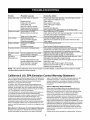
Horsepower: 5
Engine Oil: SAE 5W30
Fuel: Unleaded Regular
Spark Plug: RJ19LM
Eng he: Craftsman Eng ne Moode 143.045001
Model Number a safe
Serial Number ...........................................................
Date of Purchase ......................................................
Record both serial number and date of purchase and keep in
,lace for future reference.

_lb WARNING: This symbol points out important safety instructions which, if not followed, could endanger
the personal safety and/or property of yourself and others. Read and follow all instructions in this manual
before attempting to operate this machine. Failure to comply with these instructions may result in personal
injury. When you see this symbol--heed its warning.
,_ WARNING: Engine Exhaust, some of its constituents, and certain vehicle components contain or emit
chemicals known to State of California to cause cancer and birth defects or other reproductive harm.
DANGER: This machine was built to be operated according to the rules for safe operation in this manual. As with
any type of power equipment, carelessness or error on the part of the operator can result in serious injury. This
machine is capable of amputating hands and feet and throwing objects. Failure to observe the following safety
instructions could result in serious injury or death.
Training
1. Read, understand, and follow all instructions on the
machine and in the manual(s) before attempting to
assemble and operate. Keep this manual in a safe place
for future and regular reference and for ordering
replacement parts.
2. Be familiar with all controls and their operation. Know
how to stop the machine and disengage controls.
3. Never allow children under 14 years old to operate this
machine. Children 14 years old and over should read and
understand the operation instructions and safety rules in
this manual and should be trained and supervised by a
parent.
4. Never allow adults to operate this machine without
proper instruction.
5. Thrown objects can cause serious personal injury. Plan
your snow-throwing pattern to avoid discharge of material
toward roads, bystanders and the like.
6. Keep bystanders, helpers, pets and children at least 75
feet from the machine while it is in operation. Stop
machine if anyone enters the area.
7. Exercise caution to avoid slipping or falling, especially
when operating in reverse.
Preparation
1. Thoroughly inspect the area where the equipment is to
be used. Remove all doormats, newspapers, sleds,
boards, wires and other foreign objects, which could be
tripped over or thrown by the auger/impeller.
2. Always wear safety glasses or eye shields during
operation and while performing an adjustment or repair to
protect your eyes. Thrown objects which ricochet can
cause serious injury to the eyes.
3. Do not operate without wearing adequate winter outer
garments. Do not wear jewelry, long scarves or other
loose clothing, which could become entangled in moving
parts. Wear footwear which will improve footing on
slippery surfaces.
4. Use a grounded three-wire extension cord and
receptacle for all units with electric start engines.
5. Adjust collector housing height to clear gravel or crushed
rock surfaces.
6. Disengage all clutch levers before starting the engine.
7. Never attempt to make any adjustments while engine is
running, except where specifically recommended in the
operator's manual.
8. Let engine and machine adjust to outdoor temperature
before starting to clear snow.
9. To avoid personal injury or property damage use extreme
care in handling gasoline. Gasoline is extremely
flammable and the vapors are explosive. Serious
personal injury can occur when gasoline is spilled on
yourself or your clothes, which can ignite. Wash your skin
and change clothes immediately.
a. Use only an approved gasoline container.
b. Extinguish all cigarettes, cigars, pipes and other
sources of ignition.
c. Never fuel machine indoors.
d. Never remove gas cap or add fuel while the
engine is hot or running.
e. Allow engine to cool at least two minutes before
refueling.
f. Never over fill fuel tank. Fill tank to no more than
½ inch below bottom of filler neck to provide space
for fuel expansion.
g. Replace gasoline cap and tighten securely.
h. If gasoline is spilled, wipe it off the engine and
equipment. Move machine to another area. Wait 5
minutes before starting the engine.
i. Never store the machine or fuel container inside
where there is an open flame, spark or pilot light
(e.g. furnace, water heater, space heater, clothes
dryer etc.).
j. Allow unit to cool for 5 minutes before storing.
Operation
1. Do not put hands or feet near rotating parts, in the auger/
impeller housing or discharge chute. Contact with the
rotating parts can amputate hands and feet.
2. The auger/impeller clutch lever is a safety device. Never
bypass its operation. Doing so makes the machine
unsafe and may cause personal injury.
3. The clutch levers must operate easily in both directions
and automatically return to the disengaged position when
released.
4. Never operate with a missing or damaged discharge
chute. Keep all safety devices in place and working.
5. Never run an engine indoors or in a poorly ventilated
area. Engine exhaust contains carbon monoxide, an
odorless and deadly gas.
6. Do not operate machine while under the influence of
alcohol or drugs.

7. Mufflerandenginebecomehotandcancauseaburn.Do
nottouch.
8. Exerciseextremecautionwhenoperatingonorcrossing
gravelsurfaces.Stayalertforhiddenhazardsortraffic.
9. Exercisecautionwhenchangingdirectionandwhile
operatingonslopes.
10.Planyoursnow-throwingpatterntoavoiddischarge
towardswindows,walls,carsetc.Thus,avoiding
possiblepropertydamageorpersonalinjurycausedbya
ricochet.
11.Neverdirectdischargeatchildren,bystandersandpets
orallowanyoneinfrontofthemachine.
12.Donotoverloadmachinecapacitybyattemptingtoclear
snowattoofastofarate.
13.Neveroperatethismachinewithoutgoodvisibilityor
light.Alwaysbesureofyourfootingandkeepafirmhold
onthehandles.Walk,neverrun.
14.Disengagepowertotheauger/impellerwhen
transportingornotin use.
15. Never operate machine at high transport speeds on
slippery surfaces. Look down and behind and use care
when in reverse.
16. If the machine should start to vibrate abnormally, stop the
engine, disconnect the spark plug wire and ground it
against the engine. Inspect thoroughly for damage.
Repair any damage before starting and operating.
17. Disengage all clutch levers and stop engine before you
leave the operating position (behind the handles). Wait
until the augedimpeller comes to a complete stop before
unclogging the discharge chute, making any
adjustments, or inspections.
18. Never put your hand in the discharge or collector
openings. Always use the clean-out tool provided to
unclog the discharge opening. Do not unclog discharge
chute while engine is running. Before unclogging, shut off
engine and remain behind handles until all moving parts
have stopped completely.
19. Use only attachments and accessories approved by the
manufacturer (e.g. wheel weights, tire chains, cabs etc.).
20. If situations occur which are not covered in this manual,
use care and good judgment. Contact Sears service
center for assistance.
Maintenance & Storage
1. Never tamper with safety devices. Check their proper
operation regularly. Refer to the maintenance and
adjustment sections of this manual.
2. Before cleaning, repairing, or inspecting machine
disengage all clutchlevers and stop engine. Wait untilthe
auger/impeller come toa complete stop. Disconnect the
spark plugwire and ground against the engine toprevent
unintended starting.
3. Check bolts and screws for proper tightness at frequent
intervals to keep the machine in safe working condition.
Also, visually inspect machine for any damage.
4. Do not change the engine governor setting orover-speed
the engine. The governor controls the maximum safe
operating speed of the engine.
5. Snow thrower shave plates and skid shoes are subject to
wear and damage. For your safety protection, frequently
check all components and replace with original
equipment manufacturer's (OEM) parts only. "Use of
parts which do not meet the original equipment
specifications may lead to improper performance and
compromise safety!"
6. Check clutch controls periodically to verify they engage
and disengage properly and adjust, if necessary. Refer to
the adjustment section in this operator's manual for
instructions.
7. Maintain/replace safety/instruction labels, as necessary.
8. Observe proper disposal laws and regulations for gas,
oil, etc. to protect the environment.
9. Prior to storing, run machine a few minutes to clear snow
from machine and prevent freeze up of auger/impeller.
10. Never store the machine or fuel container inside where
there is an open flame, spark or pilot light such as a water
heater, furnace, clothes dryer etc.
11. Always refer to the operator's manual for proper
instructions on off-season storage.
Your Responsibility
Restrict the use of this power machine to persons who read,
understand and follow the warnings and instructions in this
manual and on the machine. The safety labels are shown
below for your reference.
Do not modify engine
To avoid serious injury or death, do not modify engine in any
way. Tampering with the governor setting can lead to a
runaway engine and cause it to operate at unsafe speeds.
Never tamper with factory setting of engine governor.
Notice regarding emissions
Engines which are certified to comply with California and
federal EPA emission regulations for SORE (Small Off Road
Equipment) are certified to operate on regular unleaded
gasoline, and may include the following emission control
systems: Engine Modification (EM) and Three Way Catalyst
(TWC) if so equipped.
Engine Identification Decal
This decal indicates the engine's model number, specification
and teh date of manufacture. Please look at the decal on the
engine of your equipment and record these information for
future reference.
The engine identification decal also includeds engine life
specifications for the emissions-related useful life period of
the engine. This period relates to the emission compliance life
as certified by EPA and/or CARB. To find teh life period
specification of the engine, please read the engine decal and
and locate the letter (enclosed by quotation marks) between
the words Moderate and Life Period. Match one of the
following letters with the letter printed on your decal. For
example, HSSK models are designated as:
"C"-- 125 hours
"B" -- 250 hours
"A" -- 500 hours

Unpacking
1. Remove screws from the top sides and ends of the
shipping crate.
2. Set crate panels aside to avoid tire punctures or
personal injury.
3. Remove and discard plastic bag that covers unit.
4. Remove any loose parts included with unit (i.e.,
Operator's Manual, etc).
5. Roll unit out of crate.
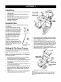
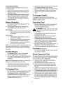
Hardware Pack
Following items make up the hardware pack for your
snow thrower:
1. Shear bolts and lock nuts (2)
The augers are secured to the auger
shaft with two shear bolts and hex
lock nuts. Ifyou hit a foreign object
or icejam, these bolts may shear.
Two replacement shear boltsand
lock nuts are provided for your
convenience. Save these until
needed.
2. Z fittings and hex nuts (2)
These four hardware pieces will be
required inthe assembly ofthe snow
thrower. Identify the items and use
as instructed.
®
®
Hardware not drawn
to size here
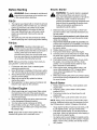
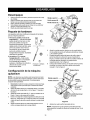
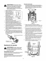
Setting Up The Snow Thrower
Your snow thrower was fully assembled at the factory
and needs minimum set-up.
NOTE: All references in this manual to left, right, top or
bottom is from the operating position only. Exceptions, if
any, will be specified.
1. Disconnect spark plug wire and ground it against
the engine to prevent unintended starting.
2. Remove hand knob A, cupped washer and carriage
screw from the lower handle. See Figure 1. Save
the hardware.
3. Loosen hand knobs B and C, shown in Figure 1, but
do not remove from the unit.
4. Raise the handle assembly up following direction of
the arrow in Figure 1. Make sure not to scrape the
paint on the unit by the eyebolt when you flip the
handle up.
5. Align the lower hole on each upper handle with the
corresponding hole on the lower handle.
Hand Knob B
Upper
Handle
Figure 1
6. Secure the right upper handle to the lower handle
with handle knob A and hardware removed in step
2. Do not tighten the knob.
7. Remove the hand knob on the eye bolt and pivot
eye bolt in the direction shown in Figure 2. Insert the
eye bolt into the lower hole of the left upper handle
and the lower handle respectively. See Figure 2.
8. Place cupped washer, with the concave side
against the handle, on the eye bolt and secure with
the hand knob D. See Figure 2.
Lower Handle
Upper
Hand Knob
Handle
ye
bolt from here
Directional
Control
Figure 2
9. Tighten all four hand knobs now.
NOTE: Make sure that spiral on the chute directional
control fully engages teeth on chute assembly. See
Figure 3.

Figure 3
10. Take a "Z" fitting from the hardware pack and insert
the Z end into the hole on the left clutch grip on the
handle panel. See Figure 4. Thread a hex nut from
hardware pack on to the Z fitting.
P
Hex Nut
Figure 4
11. Route the left cable between engine and speed
selector plate and then between handle panel and
clutch lever pivot rod. Make sure the cable is routed
correctly in the cable roller guides located at the
lower rear of the unit.
12. Thread cable onto the left "Z" fitting.
13. Assemble the right "Z" fitting on the right clutch grip
and attach the right cable in the same manner. Both
cables should have minimal slack, but not tight.
Tighten or loosen hex nuts on "Z" fittings to adjust.
IMPORTANT: If the right lock-out cable isnot adjusted,
the wheels will tend to turn. If the left lock-out cable is
not adjusted, the augers will keep on rotating.
NOTE: The drive clutch cable is routed overthe axle.
_bb WARNING: Do not over-tighten the clutch
cables. Tension on either cable in the
disengaged (up) position may override the
safety features of the machine.
Chute Clean-Out Tool
This tool and the electric extension cord are fastened
with a cable tie to the rear of the auger housing for
shipping purposes. Cut the cable tie and remove the
electric cord before operating the snow thrower.
Final Assembly & Adjustments
Auger Control
1. To check the adjustment of the auger control, push
forward on the left hand clutch grip (depress the
rubber bumper). There should be slack in the cable.
Release the clutch grip. The cable should be
straight. Make certain you can depress the auger
control grip against the left handle completely.
2. If necessary, loosen the hex lock nut and thread the
cable in (for less slack) or out (for more slack) as
necessary. Refer to Figure 4.
3. Tighten the lock nut against the cable when correct
adjustment is reached.
Traction Control & Shift Lever
1. To check the adjustment of the traction controt and
shift lever, move the shift lever all the way to the
right to fifth (5) position. With the traction control
released, push the snow thrower forward. The unit
should move forward freely. Then engage the
traction control grip. The wheels should not turn.
2. Now release the traction control grip, and push the
unit again. Move the shift lever back to the fast
reverse position, then all the way forward again.
There should be no resistance in the shift lever, and
the wheels should keep turning.
3. If you feel resistance when moving the shift lever or
the wheels stop when they should not, loosen the
jam nut on the traction control cable and unthread
the cable one turn.
4. If the wheels do not stop when you engage the
traction control grip, loosen jam nut on the traction
control cable and thread the cable in one turn.
5. Recheck the adjustment and repeat as necessary.
Tighten the jam nut to secure the cable when
correct adjustment is reached.
NOTE: For more details, refer to the Adjustment
section on page 16.
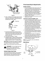
Skid Shoes
Low Position
Skid
Shoe Hex Nuts _High Position
Carriage Bolts
Figure 5

1. Locate the shave plate in Figure 6. The space
between this shave plate and ground can be
adjusted.
2. For close snow removal on smooth surface, raise
skid shoes higher. See Figure 5.
3. Place skid shoes in middle or lower position when
the area to be cleared is uneven. See Figure 5.
4. Adjust skid shoes by loosening the four hex nuts
and carriage bolts as shown in Figure 5. Move skid
shoes to desired position.
5. Make certain the entire bottom surface of skid shoe
is against the ground to avoid uneven wear on the
skid shoes. Retighten nuts and bolts securely.
Tire Pressure
The tires are overinflated for shipping purposes.
1. Check tire pressure. Maintain pressure between 15
to 20 psi. Refer to tire sidewalls for recommended
tire pressure.
NOTE: If the tire pressure is not equal in beth tires, the
unit may pull to ene side or the ether.
_ WARNING: Maximum tire under
pressure
any circumstance is 20 psi. Equal tire pressure
should be maintained at all times. Excessive
pressure (over 20 psi) when seating beads
may cause tire!rim assembly to burst with force
sufficient to cause serious injury.

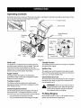
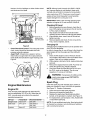
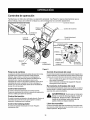
Operating Controls
Be familiar with all the controls and their proper operation. See Figure 6 and follow descriptions given below. Know
how to stop the machine and disengage them quickly.
Chute ( Traction Control
Shift Leve_ ger Control
Gas Fill
Discharge
Chute
Chute Directional
,.--Control
Auger
Plate
*_Skid Shoe
Figure 6
Shift Lever
The shift lever is located below the handle panel and
should be used to determine ground speed. There are
five forward and two reverse speeds on this unit--
positionone (1) is the slowest and positionfive (5) is the
fastest; among reverse speeds, R2 isfaster.
Auger Control
The auger control is located on the left handle.
Squeeze the auger control grip to engage the augers.
Release to stop the augers.
Traction Control
The traction control is located on the right handle.
Squeeze the traction control grip to engage the wheel
drive. Release to stop.
Chute Directional Control
The chute directional control is located on left side of
the snow thrower. To change the direction in which
snow is thrown, turn chute directional control as follows:
Crank clockwise to discharge to the left.
Crank counterclockwise to discharge to the right.
Throttle Control
The throtttecontrol islocated on the engine. Itregulates
the speed of the engine.
Ignition Key
The ignition key must be inserted in the switch to start
the unit. Remove the ignition key when snow thrower is
not in use. Do not turn ignition key.
Chute Clean-Out Tool
The chute clean-out tool is designed to clear a clogged
discharge chute. Refer to page 10 for instructions on
how to properly use it.
,_ WARNING: Never use hand to clear a
your
clogged discharge chute. Shut off engine and
remain behind handles until all moving parts
have stopped before unclogging.
To Stop Engine
Move throttle control to "stop" or "off" position; remove
ignition key and disconnect spark plug.

Before Starting
_ WARNING: Read, understand, and follow all
instructions and warnings on the machine and
in this manual before operating.
Fill Oil
1. The engine was shipped with oil. Check the oil level
before operating. After the initial use, you will have
to fill up as necessary. Be careful not to overfill.
2. Before filling up gas in the engine for the first
time, open the gas tank cap, and locate a white
plastic cap underneath. Remove this cap and
discard it.
3. The spark plug wire was disconnected for safety.
Attach spark plug wire to spark plug before starting.
Fill Gas
_lb ARNING: Gasoline is flammable and
caution must be used when handling or storing
it. Do not fill fuel tank while the snow thrower is
running, when itis hot or when it is in an
enclosed area. Keep your snow thrower away
from any open flame or an electrical spark and
do not smoke while filling the fuel tank.
NOTE: Make sure that the containerfrem which you
pour gasoline is clean and rust-free .
1. Fill fuel tank with clean, fresh, unleaded grade
automotive gasoline only.
2. Never fill fuel tank completely. Fill the tank to within
1/4"-1/2" from the top to provide for fuel expansion.
3. Always fill fuel tank outdoors and use a funnel or
spout to prevent spilling.
4. Make sure to wipe off any spilled fuel before
starting the engine.
5. Store gasoline in a clean, approved container and
keep the cap in place on the container.
To Start Engine
1. Attach spark plug wire to spark plug. Make certain
the metal loop on the end of the spark plug wire
(inside the boot) is fastened securely over the metal
tip on the spark plug.
2. Make certain the auger and drive clutch levers are
in the disengaged (released) position.
3. Turn fuel valve counter-clockwise to OPEN.
4. Move throttle control up to FAST position. Insert
ignition key into slot. Make sure it snaps into place.
Do not turn key.
NOTE: Engine will not start unless ignition key is
inserted into ignition slot in carburetor cover.
Electric Starter
,_ WARNING: The electric starter is equipped
with a grounded three-wire power cord and
plug, and is designed to operate on 120 volt AC
household current. It must be used with a
propedy grounded three-prong receptacle at all
times to avoid the possibility of electdc shock.
Follow all instructions carefully prior to
operating the electric starter.
1. Determine that your house widng is a three-wire
grounded system. Ask a licensed electrician if you
are not certain.
If your house wiring system is not a three-wire
grounded system, do not use this electdc starter
under any conditions.
If your home electrical system is grounded, but
a three-hole receptacle is not available, one should
be installed by a licensed electrician before using
the electric starter.
2. Rotate choke knob to OFF position.
3. Push primer three times to pdme the engine.
4. Connect power cord to switch box on engine. Plug
the other end of power cord into a three-prong 120-
volt, grounded, AC receptacle.
5. Push starter button to crank engine. As you crank
the engine, move choke knob to FULL choke
position. Do not operate electdc starer for more
than 5 seconds on each attempt.
6. When engine starts, release starter button, and
move choke gradually to OFF. If engine falters,
move choke immediately to FULL and then
gradually to OFF.
7. When disconnecting the power cord, always unplug
from the three-prong receptacle first, and then from
the snow thrower.
Recoil Starter
1. Rotate choke knob to FULL choke position (cold
engine start).
2. If engine is warm, place choke in OFF position
instead of FULL.
3. Push pdmer button two or three times for cold
engine start.
4. If engine is warm, push primer button only once.
NOTE: Always cover vent hole in primer button when
pushing. Additional priming may be necessary for first
start if tempereture is below 15 degrees Fahrenheit.
Grasp starter handle and pull rope out slowly, until
it pulls slightly harder. Let rope rewind slowly.
Pull starter handle rapidly. Do not allow handle to
snap back. Allow it to rewind slowly while keeping a
firm hold on the starter handle.
As engine warms up and begins to operate evenly,
rotate choke knob slowly to OFF position. If engine
falters, return to FULL choke, then slowly move to
OFF position.

Frozen Recoil Starter
If the starter isfrozen and wilt not turn the engine,
proceed as follows:
1. Pull as much rope out of the starter as possible.
2. Release the starter handle and let it snap back
against the starter.
3. If the engine still fails to start, repeat the first two
steps. If continued attempts do not free starter,
follow the electric starter procedures to start.
4. Avoid freezing of the recoil starter by following
instructions below.
Before Stopping
1. Run engine for a few minutes to help dry off any
moisture on engine.
2. Avoid freezing of the starter by following these
steps before stopping the snow thrower:
Recoil Starter
a. With the engine running, pull the starter rope
with a rapid, continuous full arm stroke three
or four times.
Electric Starter
a. Connect power cord to switch box, then to
120 Volt AC receptacle.
b. While engine is running, push starter button
and spin the starter for several seconds.
c. Disconnect power cord from the receptacle
first, then from the snow thrower.
NOTE: The unusual sound from pulling the starter rope
in the case of the recoil starter, or from spinning the
starter in the case of the electric starter, will not harm
the engine.
To Stop Engine
1. Move throttle control to "stop" or "off' position.
2. Remove the ignition key. Do not turn key.
3. Disconnect the spark plug wire from the spark plug
to prevent accidental starting while equipment is
unattended.
NOTE: Do not lose ignition key. Keep it in a safe place.
Engine will not start without the ignition key.
4. Wipe all snow and moisture from the carburetor
cover in the area of the control levers. Also, move
control levers back and forth several times.
To Engage Drive
1. With the engine running near top speed, move shift
lever into one of the five FORWARD positions or
two REVERSE positions. Select a speed
appropriate for the snow conditions that exist. Use
the slower speeds until you are familiar with the
operation of the snow thrower.
2. Squeeze the auger control grip and the augers will
turn. Release it and the augers wilt stop.
3. Squeeze traction control grip and the snow thrower
will move. Release it and drive motion will stop.
4. NEVER move shift lever without releasing drive
clutch.
To Engage Augers
To engage the augers and start throwing snow,
squeeze the auger control grip against the left handle.
Release to stop the augers.
Operating Tips
Allow the engine to warm up for a few minutes as
the engine will not develop full power until it
reaches operating temperature.
_ WARNING: Muffler, engine and surrounding
areas become hot and can cause a burn. Do
not touch.
For most efficient snow removal, remove snow
immediately after it falls.
Discharge snow downwind whenever possible.
Slightly overlap each previous swath.
Set the skid shoes 1/4" below the scraper bar for
normal usage. The skid shoes may be adjusted
upward for hard-packed snow. Adjust downward
when using on gravel or crushed rock.
Be certain to follow the precautions listed under "To
Stop Engine" to prevent possible freeze-up.
Clean the snow thrower thoroughly after each use.
Tire Chains (ifequipped)
Tire chains, if equipped, should be used whenever
extra traction is needed.
Chute Clean-Out Tool
The chute clean-out tool is conveniently fastened to the
rear of the auger housing with a mounting clip. Never
use your hand to clean a clogged chute.
1. Release both the auger control lever and the
traction/auger control locklever.
2. Stop the engine by removing the ignition key.
3. Remove the clean-out tool from the clip which
secures itto the rear of the auger housing. See
Figure 6.
4. Use the shovel-shaped end of the clean-out tool to
remove any snow and ice in the discharge chute.
5. Re-fasten the clean-out tool to the mounting clip on
the rear of the auger housing and restart engine.
6. While standing in the operator's position (behind
the snow thrower), engage the auger clutch lever
for a few seconds to clear any remaining snow or
ice from the discharge chute before continuing to
clear snow.
10

General Recommendations
Always observe safety rules when performing any
maintenance.
The warranty on this snow thrower does not cover
items that have been subjected to operator abuse
or negligence. To receive full value from the
warranty, operator must maintain the snow thrower
as instructed in this manual.
Follow the maintenance schedule given below.
Periodically check all fasteners and make sure
these are tight.
_ WARNING: Before lubricating, repairing, or
inspecting, disengage all clutch levers and stop
engine. Wait until all moving parts have come
to a complete stop. Disconnect spark plug wire
and ground it against the engine to prevent
unintended starting.
Maintenance Schedule
Maint. Tasks Before Aftereach &fterfirst2 Every25 Every50 Before Service Dates
_=achuse use hours hours hours storage
operation operation operation
Product: , , ,
Lubricate pivotpoints I I I I _ I
Clean equipment
Clean skid shoe
Check V belts
Engine:
Check engine oil
Change engine oil _
Check spark plug I I I I
Empty fuel system
,/
,/
iiiiiiiiiii
,/
,/
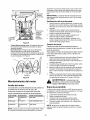
Lubrication
Wheels: Oil or spray lubricant into bearings at
wheels at least once a season. Pullktickpin,
remove wheels, clean and coat axles with a
multipurpose automotive grease. See Figure 7.
Oil bearings
Klick Pin , lubricant
Figure 7
Gear Shaft: Lubricate the gear shaft with a good
all-weather multi-purpose light grease at least once
a season or after every 25 hours of operation. Keep
all grease and oil off the friction wheel and drive
plate.
IMPORTANT: When lubricating engine or draining oil,
avoid spillage onto transmission parts.
Gear Case: The worm gear case has been filled
with grease at the factory. If disassembled for any
reason, lubricate with 2 ounces of shell grease.
IMPORTANT: Do not overfill the gear case. Damage to
the seals could result. Be sure the vent plug is free of
grease in order to relieve pressure.
Drive and Shifting Mechanism: Remove rear
cover. Oil any chains, sprockets, gears, bearings,
shafts, and shifting mechanism at least once a
season. See Figure 8. Use engine oil or a spray
11

lubricant. Avoid oil spillage on rubber friction wheel
and aluminum drive plate.
Lever
Lube
Gear
Sha_
friction wheel
and drive plate
Figure 8
Chute Directional Control: The worm gear on the
chute control should be lubricated with multi-
purpose automotive grease.
Auger Shaft: At least once a season, remove
shear bolts on auger shaft. Oil or spray lubricant
inside shaft and lubricate the auger bearings. See
Figure 9.
Shear Bolts
Bearings
Figure 9
Engine Maintenance
Engine Oil
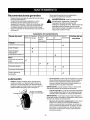
Only use high quality detergent oil rated with API
service classification SF, SG or SH. Select the oil's
SAE viscosity grade according to the expected
operating temperature:
Oil Type Temperature Recommended Oil
Straight Grade Above32°F SAE 3OW
Multi Grade 0°Fto 32°F SAE 5W30or
SAE 10W
Synthetic BelowO°F SAE 0W30
NOTE: Although multi-viscosity oils(5W30, 10W30
etc.) improve starting in cold weather, these multi-
viscosity oils will result in increased oil consumption
when used above 32°F. Check your snow thrower's
engine oil level more frequently to avoid possible
engine damage from running low on oil.
IMPORTANT: Refer to the viscosity chart for proper
selection of engine oil. Do not use SAE 10W40 oil.
Checking Oil Level
1. Before operating the snow thrower, check the oil
level. With engine on level ground, the oil must be
to FULL mark on dipstick.
2. Stop engine and wait several minutes before
checking oil level. Remove oilfillcap and dipstick.
3. Wipe dipstick clean, insertitinto oilfill hole and
tighten securely.
4. Remove dipstick and check. Ifoilis not up to the
FULL mark on dipstick,add oil.
Changing Oil
Change engine oil after first two hours of operation and
every 25 hours thereafter.
In order to change the oil, you will have to first drain the
spent engine oil from the engine and then refill with
fresh oil.
1. Drain oil while engine is warm. Remove oil drain
cap located at the bottom of the recoil starter of the
engine. Catch oil in a suitable container.
2. When engine is drained of all oil, replace drain plug
securely.
3. Remove the dipstick from the oil fill. Pour fresh oil
slowly through the plug. Replace dipstick.
4. Check and make sure that the level of oil is up to
the FULL mark on the dipstick. The oil sump
capacity is 21 ounces or 0.62 liters.
_i_ WARNING: Temperature of muffler and its
nearby areas may exceed 150° F(65°C).
Avoid these areas.
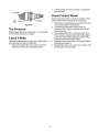
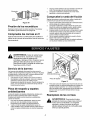
Spark Plug
Clean the spark plug and reset the gap to 0.030" at
least once a season or every 100 hours of operation.
See Figure 10. Replace if necessary.
1. Clean area around the spark plug base.
2. Remove and inspect the spark plug.
3. Replace the spark plug if electrodes are pitted,
burned, or the porcelain is cracked. See Figure 10.
4. For replacement, use Champion J-8C, Autolite 356
or equivalent spark plug.
NOTE: Do not sandblast spark plug. Spark plug should
be cleaned by scraping or wire brushing and washing
with a commercial solvent.
12

2. Visually inspect for frayed, cracked, or excessively
Electrodes worn out belts.
.030" Porcelain
Gap
Figure 10
Tire Pressure
Maintain equal pressure on both tires. For more details
on this, follow instructions on page 7.
Check V-Belts
Follow instructionsbelow to check the condition of the
drive belts every 50 hours of operation.
1. Remove the plastic belt cover on the front of the
engine by removing two self-tapping screws.
Check Friction Wheel
Follow instructions below to check the condition of the
friction wheel rubber every 25 hours of operation.
1. Remove the six self-tapping screws from the frame
cover underneath the snow thrower.
2. Visually inspect the friction wheel rubber for
excessive wear, cracks, or loose fit on the friction
wheel drive hub.
3. Also engage the traction control and check if the
friction wheel is making contact with friction plate. If
it does not make contact, adjust the traction drive
cable and recheck the friction wheel.
4. Replace friction wheel rubber if necessary. Refer to
instructions on page 15.
5. Re-attach the frame cover to the snow thrower with
the hardware removed earlier.
13

i_hl WARNING: Beforeservicing,repairing,or
inspecting,disengageallclutchleversandstop
engine.Waituntilallmovingpartshavecome
toacompletestop.Disconnectsparkplug wire
and ground it against the engine to prevent
unintended starting.
All adjustments in the Service and Adjustments
section of this manual should be checked at least
once each season.
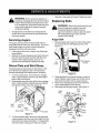
Servicing Augers
The augers are secured to the spiral shaft with two
shear bolts and hex lock nuts. See Figure 9. If you hit a
hard foreign object or ice jam, the snow thrower is
designed so that the bolts may shear.
1. If the augers will not turn, check to see if the bolts
have sheared.
2. Replace as needed. Replacement shear bolts and
hex lock nuts have been provided with the snow
thrower. When replacing bolts, spray an oil
lubricant into shaft before inserting new bolts.
Shave Plate and Skid Shoes
The shave plate and skid shoes on the bottom of the
snow thrower are subject to wear. They should be
checked periodically and replaced when necessary.
1. To remove skid shoes, remove the four carriage
bolts, cupped washers and hex nuts which attach
them to the snow thrower.
2. Reassemble new skid shoes with the four carriage
bolts, cupped washers (cupped side goes against
skid shoes) and hex nuts. See Figure 11.
bolts are to the inside of housing. Tighten securely.
Replacing Belts
_i WARNING: Disconnect spark plug wire and
ground it against the engine to prevent
unintended starting. Drain fuel into an
approved container or place a piece of plastic
film underneath the gas cap to prevent
gasoline from leaking.
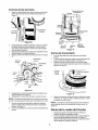
Auger Belt
1. Remove plastic belt cover from front ofthe engine
byremoving the two self-tapping screws. See
Figure 12.
Belt
Cover
Screws
2.
3.
4.
Figure 12
Drain gasoline from the snow thrower, or place a
piece of plastic under the gas cap.Tip the unit up
and forward so that it rests on auger housing.
Remove six self-tapping screws from the frame
cover underneath the snow thrower.
Roll auger belt off engine pulley. See Figure 13.
Drive
Auger Belt
Belt
X Drive
Pulley
Skid Carriage
Shoe Bolts
3.
Shave
Nuts
Figure 11
To remove shave plate, remove the carriage bolts,
cupped washers and hex nuts which attach it to the
snow thrower housing. See Figure 11. Reassemble
new shave plate, making sure heads of carriage
Idler
Pulley
Pulley
Figure 13
14

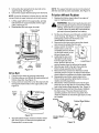
5. Unhook the idler spring from the hex bolt on the
auger housing. See Figure 14.
6. Unhook the support bracket spring from the frame.
NOTE: It may be necessary to loosen the six nuts that
connect frame to auger housing to aid in belt removal.
7. Lift the auger belt from the auger pulley, and slip
belt between the support bracket and the auger
pulley. See Figure 13.
8. Reassemble with new auger drive belt.
Friction Wheel
Assembly
Pin
Pulley /
Idler Auger Bracket
Spring Housing Spring
Figure 14
Drive Belt
1. Follow first four steps of previous instructions.
2. Pull idler pulley up, and lift belt off engine pulley and
friction wheel disc. See Figure 13.
3. Using a wrench, loosen the nut on the stop bolt until
the support bracket rests on the auger pulley. See
Figure 15.
Friction
Wheel
Disc
NOTE: The support bracket must rest on the stop bolt
afterthe new belt has been assembled. See Figure 15.
Friction Wheel Rubber
1. Replace the friction wheel rubber if any signs of
wear or cracking are found.
_b WARNING: Disconnect spark plug wire and
ground it against engine to prevent unintended
starting. Drain fuel into an approved container
or place a piece of plastic film underneath the
gas cap to prevent gasoline from leaking.
2.
3.
4.
5.
.
7.
8.
9.
10.
Tip the snow thrower up and forward, so that itrests
on the housing. See Figure 17. Remove the six
self-tapping screws from the frame cover
underneath the snow thrower.
Remove the ktick pins which secure the wheels,
and remove the wheels from the axle.
Using a wrench to hold the
shaft, loosen, but do not
completely remove, the hex
nut and bell washer on the
left end of gear shaft.
Lightly tap the hex nut to
dislodge the ball bearing
from the right side of the
frame. Remove the hex nut
and bell washer from the left end of the shaft.
Slide the gear shaft to the right, then slide the
friction wheel assembly from the shaft.
Remove the four screws from the friction wheel
assembly shown in Figure 16. Remove the friction
wheel rubber from between the friction wheel plate.
Reassemble new friction wheel rubber to the
friction wheel assembly, tightening the screws in
rotation and with equal force.
Slide friction wheel assembly back onto the gear
shaft. Be sure to align the pin on the shift rod with
hole in the friction wheel assembly. See Figure 14.
Reassemble gear shaft and the wheels. Reattach
the frame cover. Flip snow thrower back to its
operating position and remove any plastic from
under the machine or around the gas cap if you had
put it eadier.
Friction Wheel Rubber
4.
Figure 15
Slip belt between friction wheel and friction wheel
disc. See Figure 15. Remove and replace belt.
Reassemble in reverse order.
Plates
Figure 16
15

Making Adjustments
_bb WARNING: Never attempt to make any
adjustments while the engine is running,
except where specified in operator's manual.
Chute Assembly
The distance snow is thrown can be controlled by
adjusting the angle of the top section of the chute
assembly.
Skid Shoe
The space between the shave plate and the ground can
be adjusted. Refer to the Final Assembly and
Adjustments section on page 6.
Traction Control
1. Drain gasoline and engine oil from the snow
thrower. Place plastic film under the gas cap if the
snow thrower has already been operated. Tip the
snow thrower so that it rests on the auger housing.
See Figure 17.
Fram_
.
Tighten the lock nut to secure the cable when
correct adjustment is reached. Reassemble the
frame cover.
If you placed plastic under the gas cap earlier,
remove it now.
Figure 18
Auger Control
To adjustthe auger clutch, refer to Final Assembly and
Adjustments on page 6.
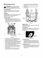
Drive Wheels
The wheels may be adjusted for two different methods
ofoperation. Follow the steps below for adjustment.
See Figure 19.
_round
Housing
Figure 17
2. Remove the frame cover underneath the snow
thrower byremoving six self-tapping screws. For
location of the frame cover, see Figure 17.
3. When thetraction control isreleased, there must be
clearance between the friction wheel and the ddve
plate in all positionsof the shift lever. When the
traction controlis engaged, the friction wheel must
contact the drive plate. See Figure 18.
4. Ifany one of these are not occuring, adjustment is
necessary. Followthe steps below to adjust the
traction control.
5. Loosen the lock nuton the traction controlcable
and thread the cable in or out as necessary.
Figure 19
One Wheel Driving
1. On the right side of the unit, place ktick pin in the
outside axle hole only. Do not place pin through
wheel hub. This position gives power drive to the
left wheel only, making the unit easier to maneuver.
Both Wheels Driving
2. Rotate wheel assembly to align hole in the hub with
the inner hole on the axle shaft. Insert klick pin in
the hole. Outer axle shaft hole should be visible.
See Figure 19.
16

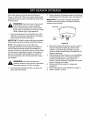
Ifthesnowthrowerwiltnotbeusedfor30daysor
longer,orattheendofthesnowseasonwhenthelast
possibilityofsnowisgone,theequipmentneedstobe
storedproperly.
_b WARNING: Never store snow thrower with
fuel in tank indoors or in poorly ventilated
areas, where fuel fumes may reach an open
flame, spark or pilot light as on a furnace, water
heater, clothes dryer or gas appliance.
1. Remove all gasoline from the carburetor and the
fuel tank to prevent gum deposits from forming on
these parts and harming the engine.
IMPORTANT: Fuel left in engine during warm weather
deteriorates and will cause serious starting problems.
NOTE: Fuel stabilizer (such as STA-BIL) is an
acceptable alternative in minimizing the formation of
fuel gum deposits during storage. Add stabilizer to
gasoline in fuel tank or storage container. Always follow
mix ratio found on stabilizer container. Run engine at
least 10 minutes after adding stabilizer to allow it to
reach the carburetor. Do not drain carburetor if using
fuel stabilizer.
_ WARNING: Drain fuel into approved
container outdoors, away from any open flame.
Be certain engine is cool. Do not smoke.
2. Run the engine until the fuel tank is empty and it
stops due to lack of fuel
3. Drain carburetor by pressing upward on bowl drain,
located below the carburetor cover. See Figure 20.
IMPORTANT: Do not drain carburetor if using fuel
stabilizer. Never use engine or carburetor cleaning
products in the fuel tank.
Carburetor
Bowl
Drain
Figure 20
4. Remove the spark plug and pour one (1) ounce of
engine oil through the spark plug hole into the
cylinder. Cover spark plug hole with a rag and
crank the engine several times to distribute the oil.
Replace spark plug.
5. When storing the snow thrower in an unventilated
or metal storage shed, care should be taken to
rustproof the equipment. Using a light oil or
silicone, coat the equipment, especially any chains,
springs, bearings and cables.
6. Remove all dirt from exterior of engine and
equipment.
7. Follow lubrication recommendations on page 11.
8. Store in a clean, dry area.
17

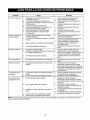
Trouble Possible Cause(s) Corrective Action
Engine failsto start Fueltank empty,or stalefuel,
Engine runs erratic
Water or dirt in fuel system,
Loss of power Spark plug wire loose,
Gas cap vent hole plugged.
Exhaust port plugged.
Engine overheats Carburetor not adjusted
properly.
Blocked fuel line,
Choke not in ON position
Faulty spark plug.
Key not in switch on engine,
Spark plug wire disconnected.
Primer button not depressed.
Unit running on CHOKE.
Blocked fuel line or stale fuel,
Fill tank with clean, flesh gasoline. Fuel will not last over thirty
days unless a fuel stabilizer is used.
Clean fuel line,
Move switch to ON position
Clean, adjust gap or replace.
Insert key,
Connect spark plug wire.
Prime engine 5 times, See instructions for starting engine.
Move choke lever to OFF position.
Clean fuel line; fill tank with clean flesh gasoline, Fuel will not last
over thirty days unless a fuel stabilizer is used,
Drain fuel tank. Refill with fresh fuel.
Connect and tighten spark plug wire.
Remove ice and snow from cap, Be certain vent hole is clear.
Clean engine.
Contact Sears service center,
Incorrect fuel mixture. Drain fuel tank. Refill with proper fuel mixture,
Excessive vibration Loose parts or damaged auger. Stop engine immediately and disconnect spark plug wire. Tighten
all bolts and nuts, Make all necessary repairs. Ifvibration
continues, have unit serviced by an authorized service dealer,
Unit fails to propel Incorrect adjustment of drive cable. Adjust drive cable. Refer to page 9 of this manual.
itself Drive belt loose or damaged. Replace drive belt. Refer to page 17 of this manual.
Unit fails to Discharge chute clogged, Stop engine immediately and disconnect spark plug wire. Clean
discharge snow discharge chute and inside of auger housing,
Foreign object lodged in auger. Stop engine immediately and disconnect spark plug wire. Remove
incorrect adjustment of drive cable, object from auger,
Drive belt loose or damaged. Adjust drive cable. Refer to page 9 of this manual.
Shear bolts have sheared. Replace drive belt. Refer to page 17 of this manual.
Replace with new shear bolts,
NOTE: This section addresses minor service issues. For further details, contact Sears service center or call the
numbers listed on the back of this manual.
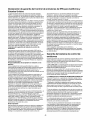
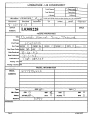
California & U.S. EPA Emission Control Warranty Statement
The U. S. Environmental Protection Agency ("EPA'), the California Air
Resources Board ("CARB") and Tecumseh Products Co. are pleased
to explain the Federal and California Emission Control Systems
Warranty on your new small off-road engine.
In California, new 1995 and later small off-road engines must be
designed, built and equipped to meet the State's stringent anti-smog
standards. In other states, new 1997 and later model year engines
must be designed, built and equipped, at the time of sale, to meet the
U.S. EPA regulations for small non-road engines.
Tecumseh Products Co. will warrant the emission control system on
your small off-road engine for the periods of time listed below,
provided there has been no abuse, neglect, unapproved modification,
or improper maintenance of your small off-road engine. Your
emission control system may include parts such as the carburetor,
ignition system and exhaust system. Also included may be the
compression release system and other emission-related assemblies.
Where a warrantable condition exists, Tecumseh Products Co. will
repair your small off-road engine at no cost to you for diagnosis, parts
and labor.
Manufacturer's Emission Control System Warranty
Emissioncontrol systemson 1995 and latermodel yearCalifornia
smalloff-road engines arewarrantedfortwo years as hereinafter
noted. In other states, 1997 and later model year engines are also
warranted for two years, if, during such warranty period, any
emission-related part on your engine is defective in materials or
workmanship, the part will be repaired or replaced by Tecumseh
Products Co.
Owner's Warranty Responsibilities
As the small off-road engine owner, you are responsible for the
performance of the required maintenance listed in your Owner's
Manual, but Tecumseh Products Co. will not deny warranty solely
due to the lack of receipts or for your failure to provide written
evidence of the performance of all scheduled maintenance.
As the small off-road engine owner, you should, however, be aware
that Tecumseh Products Co. may deny you warranty coverage if your
small off-road engine or a part thereof has failed due to abuse,
neglect, improper maintenance or unapproved modifications. You are
responsible for presenting your small off-road engine to a Tecumseh
Authorized Service Outlet (any Tecumseh Registered Service Dealer,
Tecumseh Authorized Service Distributor or Tecumseh Central
Warehouse Distributor) as soon as a problem exists. The warranty
repairs should be completed in a reasonable amount of time, not to
exceed 30 days.
Warranty service can be arranged by contacting either Authorized
18

Tecumseh Servicing Dealer or bycontacting Tecumseh Products Co.,
c/o Service Manager, Engine and Transmission Group Service
Division, 900 North Street, Grafton, W153024-1499. Telephone 1-262-
377-2700 [or in USA/Canada call 1-800-558-5402] or see your local
telephone yellow pages under "Engines, Gasoline" for the name,
address and telephone number of a Authorized Tecumseh Servicing
Dealer near you.
Important Note
This warranty statement explains your rights and obligations under the
Emission Control System Warranty ("ECS Warranty") which is provided
to you by Tecumseh Products Co. pursuant to California law.
Tecumseh Products Co. also provides to original purchasers of new
Tecumseh Products Co. engines. The Tecumseh Products Co. Limited
Warranties for New Tecumseh Engine and Electronic Ignition Modules
("Tecumseh Products Co. Warranty") which is enclosed with all new
Tecumseh Products Co. engines on a separate sheet.
The ECS Warranty applies only to the emission control system of your
new engine.To the extent that there is any conflict in terms between the
ECS Warranty and the Tecumseh Products Co. Warranty, the ECS
Warranty shall apply except in any circumstances in which the
Tecumseh Products Co. Warranty may provide a longer warranty
pedod. Both the ECS Warranty and the Tecumseh Products Co.
Warranty describe important dghts and obligations with respect to your
new engine.
Warranty service can only be performed by a Tecumseh Products Co.
Authorized Servicing Dealer. At the time of requesting warranty
service, evidence must be presented of the date of sale to the odginal
purchaser. The purchaser shall pay any charges for making service
calls and/or for transporting the products to and from the place where
the inspection and/or warranty work is performed. The purchaser shall
be responsible for any damage or loss incurred in connection with the
transportation of any engine or any part(s) thereof submitted for
inspection and/or warranty work.
If you have any questions regarding your warranty rights and
responsibilities, you should contact Tecumseh Products Co. at 1-262-
377-2700 or in USA/Canada call 1-800-558-5402.
Emission Control System Warranty
Emission Control System Warranty ("ECS Warranty") for 1995 and
later model year California small off-road engines (for other states,
1997 and later model year engines):
A, APPLICABILITY: This warranty shall apply to 1995 and later
model year California small off-road engines (for other
states, 1997 and later model year engines). The ECS Warranty Period
shall begin on the date the new engine or equipment is delivered to its
original, end-use purchaser, and shall continue for 24 consecutive
months thereafter.
warranted for the remainder of the ECS Warranty Pedod prior to the
first scheduled replacement point for such emissions-related part.
4. Repair or replacement of any warranted, emissionsrelated part
under this ECS Warranty shall be performed at no charge to the owner
at a Tecumseh Authorized Service Outlet.
5. The owner shall not be charged for diagnostic labor which leads to
the determination that a part covered by the ECS Warranty is in fact
defective, provided that such diagnostic work is performed at a
Tecumseh Authorized Service Outlet.
B, GENERAL EMISSIONS WARRANTY COVERAGE:
Tecumseh Products Co. warrants to the original, end-use purchaser of
new engine or equipment and to each subsequent purchaser that its
small off-road engines are:
1. Designed, built and equipped so as to conform with all applicable
regulations adopted by the Air Resources
Board pursuant to its authority in Chapters 1 and 2, Part 5, Division 26
of the Health and Safety Code, and
2. Free from defects in materials and workmanship which,at any time
during the ECS Warranty Period, will cause a warranted emissions-
related part to fail to be identical in all material respects to the part as
described in the engine manufacturer's application for certification.
6. Tecumseh Products Co. shall be liable for damages to other original
engine components or approved modifications proximately caused by
a failure under warranty of an emissiomrelated part covered by the
ECS Warranty.
7. Throughout the ECS Warranty Period, Tecumseh Products Co. shall
maintain a supply of warranted emission-related parts sufficient to
meet the expected demand for such emission-related parts.
8. Any Tecumseh Products Co. authorized and approved emission-
related replacement part may be used in the performance of any ECS
Warranty maintenance or repair and will be provided without charge to
the owner. Such use shall not reduce Tecumseh Products Co. ECS
Warranty obligations.
C. The ECS Warranty only pertains to emissions-related parts on your
engine, as follows:
1. Any warranted, emissions-related parts which are not scheduled for
replacement as required maintenance in the Owner's Manual shall be
warranted for the ECS Warranty Pedod. If any such part fails during the
ECS Warranty Period, it shall be repaired or replaced by Tecumseh
Products Co. according to Subsection 4 below. Any such part repaired
or replaced under the ECS Warranty shall be warranted for any
remainder of the ECS Warranty Period.
2. Any warranted, emissions-related part which is scheduled only for
regular inspection as specified in the Owner's Manual shall be
warranted for the ECS Warranty Pedod. A statement in such written
instructions to the effect of "repair or replace as necessary", shall not
reduce the ECS Warranty Pedod. Any such part repaired or replaced
under the ECS Warranty shall be warranted for the remainder of the
ECS Warranty Period.
3. Any warranted, emissions-related part which is scheduled for
replacement as required maintenance in the Owner's Manual, shall be
warranted for the period of time prior to the first scheduled replacement
point for that part. Ifthe part fails prior to the first scheduled
replacement, the part shall be repaired or replaced by Tecumseh
Products Co. according to Subsection 4 below. Any such emissions-
9. Unapproved add-on or modified parts may not be used to modify or
repair a Tecumseh Products Co. engine. Such use voids this ECS
Warranty and shall be sufficient grounds for disallowing an ECS
Warranty claim. Tecumseh Products Co. shall not be liable hereunder
for failures of any warranted parts of a Tecumseh Products Co. engine
caused by the use of such an unapproved add-on or modified part.
Emission-Related Parts include the following:
1. Carburetor Assembly and its Internal Components
a. Fuel filter
b. Carburetor gaskets
c. Intake pipe
2. Air Cleaner Assembly
a. Air filterelement
3. ignition System, including:
a. Spark plug
b. Ignition module
c. Flywheel assembly
4. Catalytic Muffler (if so equipped)
a. Muffler gasket (if so equipped)
b. Exhaust manifold (ifsoequipped)
5. Crankcase Breather Assembly and its Components
a. Breather connection tube
related part repaired or replaced under the ECS Warranty, shall be
19

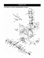
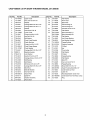
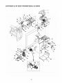
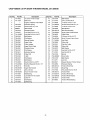
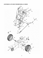
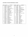
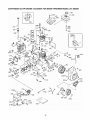
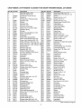
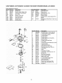
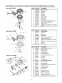
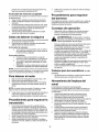
CRAFTSMAN 5.0 HP SNOW THROWER MODEL 247.886640
6_ 6_
14 13
14
/
65 36\
/
\
4O
.41
28
/
3O
/43
/
44
47
20
Page is loading ...
Page is loading ...
Page is loading ...
Page is loading ...
Page is loading ...
Page is loading ...
Page is loading ...
Page is loading ...
Page is loading ...
Page is loading ...
Page is loading ...
Page is loading ...
Page is loading ...
Page is loading ...
Page is loading ...
Page is loading ...
Page is loading ...
Page is loading ...
Page is loading ...
Page is loading ...
Page is loading ...
Page is loading ...
Page is loading ...
Page is loading ...
Page is loading ...
Page is loading ...
Page is loading ...
Page is loading ...
Page is loading ...
-
 1
1
-
 2
2
-
 3
3
-
 4
4
-
 5
5
-
 6
6
-
 7
7
-
 8
8
-
 9
9
-
 10
10
-
 11
11
-
 12
12
-
 13
13
-
 14
14
-
 15
15
-
 16
16
-
 17
17
-
 18
18
-
 19
19
-
 20
20
-
 21
21
-
 22
22
-
 23
23
-
 24
24
-
 25
25
-
 26
26
-
 27
27
-
 28
28
-
 29
29
-
 30
30
-
 31
31
-
 32
32
-
 33
33
-
 34
34
-
 35
35
-
 36
36
-
 37
37
-
 38
38
-
 39
39
-
 40
40
-
 41
41
-
 42
42
-
 43
43
-
 44
44
-
 45
45
-
 46
46
-
 47
47
-
 48
48
-
 49
49


Craftsman 247.88664 User manual
- Category
- Snow throwers
- Type
- User manual
- This manual is also suitable for
Ask a question and I''ll find the answer in the document
Finding information in a document is now easier with AI
in other languages
Related papers
-
Craftsman 247888540 Owner's manual
-
Champion Power Equipment 40011 User manual
-
-
-
-
-
-
-
-
Other documents
-
Sears 247.88853 User manual
-
-
-
MTD 60-3754-4 User manual
-
Yard-Man Snow Blower 600 User manual
-
Bolens 31AE5MLH565 Owner's manual
-
-
-
Tecumseh OHH50 User manual
-
Yard Machines 31A-150-000 Owner's manual