Astria Fireplaces DRL4000 Instruction Sheet
- Category
- Fireplaces
- Type
- Instruction Sheet
This manual is also suitable for
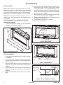
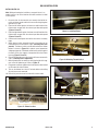
Astria Fireplaces DRL4000 is a thermostatically-controlled blower kit that improves the heat circulation of your gas fireplace, ensuring a more comfortable and even temperature in your room.
Features:
- Variable speed blower control for customized comfort levels
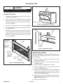
- Easy installation with pre-installed magnets for secure blower placement
- Thermal switch for automatic blower activation when the fireplace is in use
Possible use cases:
- Enhance the heating efficiency of your gas fireplace, reducing energy consumption
- Distribute heat more evenly throughout the room, eliminating cold spots
Astria Fireplaces DRL4000 is a thermostatically-controlled blower kit that improves the heat circulation of your gas fireplace, ensuring a more comfortable and even temperature in your room.
Features:
- Variable speed blower control for customized comfort levels
- Easy installation with pre-installed magnets for secure blower placement
- Thermal switch for automatic blower activation when the fireplace is in use
Possible use cases:
- Enhance the heating efficiency of your gas fireplace, reducing energy consumption
- Distribute heat more evenly throughout the room, eliminating cold spots


-
 1
1
-
 2
2
-
 3
3
-
 4
4
-
 5
5
-
 6
6
-
 7
7
-
 8
8


Astria Fireplaces DRL4000 Instruction Sheet
- Category
- Fireplaces
- Type
- Instruction Sheet
- This manual is also suitable for
Astria Fireplaces DRL4000 is a thermostatically-controlled blower kit that improves the heat circulation of your gas fireplace, ensuring a more comfortable and even temperature in your room.
Features:
- Variable speed blower control for customized comfort levels
- Easy installation with pre-installed magnets for secure blower placement
- Thermal switch for automatic blower activation when the fireplace is in use
Possible use cases:
- Enhance the heating efficiency of your gas fireplace, reducing energy consumption
- Distribute heat more evenly throughout the room, eliminating cold spots
Ask a question and I''ll find the answer in the document
Finding information in a document is now easier with AI
Related papers
-
Astria Fireplaces Allume Instruction Sheet
-
-
-
-
-
-
-
-
-
Other documents
-
Superior Fireplaces DRL3500 Operating instructions
-
-
-
-
-
-
-
-
Superior DRT2033 Installation And Operation Instructions Manual
-