International comfort products R2H336GHR Installation guide
- Category
- Heat pumps
- Type
- Installation guide
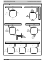
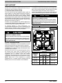
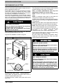
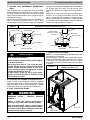
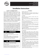
International Comfort Products R2H336GHR is a high-performance R-22 heat pump outdoor component designed to provide efficient and reliable heating and cooling for your home. With its advanced features, including adjustable clearances, ground-level or rooftop installation options, and a durable construction, this unit is engineered to deliver optimal comfort and energy savings.
International Comfort Products R2H336GHR is a high-performance R-22 heat pump outdoor component designed to provide efficient and reliable heating and cooling for your home. With its advanced features, including adjustable clearances, ground-level or rooftop installation options, and a durable construction, this unit is engineered to deliver optimal comfort and energy savings.


-
 1
1
-
 2
2
-
 3
3
-
 4
4
-
 5
5
-
 6
6
-
 7
7
-
 8
8
-
 9
9
-
 10
10
-
 11
11
-
 12
12
-
 13
13
-
 14
14
-
 15
15
-
 16
16
-
 17
17
-
 18
18
-
 19
19


International comfort products R2H336GHR Installation guide
- Category
- Heat pumps
- Type
- Installation guide
International Comfort Products R2H336GHR is a high-performance R-22 heat pump outdoor component designed to provide efficient and reliable heating and cooling for your home. With its advanced features, including adjustable clearances, ground-level or rooftop installation options, and a durable construction, this unit is engineered to deliver optimal comfort and energy savings.
Ask a question and I''ll find the answer in the document
Finding information in a document is now easier with AI
Related papers
-
International comfort products R2A330GKR Installation guide
-
-
-
-
-
-
-
-
ICP C4H418GKD100 Installation guide
-
Other documents
-
 Payne PH4A Installation Instructions Manual
-
Carrier 34SCA5 User manual
-
-
ICP T4H430GKD100 Installation guide
-
Carrier 38CKW Installation And Start-Up Instructions Manual
-
 Tempstar TXH5 Installation Instructions Manual
-
ICP H4A318GKD100 Installation guide
-
 AirQuest R4A5S36AKAWA User manual
-
Carrier 24SCA4 User manual
-


