
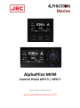
AlphaPilot MFM
Control Panel APH-5 / APH-7
Operation Manual
www.alphatronmarine.com

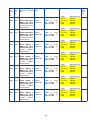
Document history
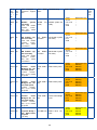
Revision Date Modifications Author
A01 February, 2017 Document was created and reviewed VS
B01 June, 2017 Document completely revised MK
C01 March, 2021
Ch.2 Control panel descriptions are updated,
4.3 “Follow-up Override” control mode is
added, Ch.5 Menu description is updated,
Ch.7 “Hardware” is added, App. A “Alert list” is
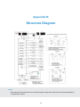
updated, App. B “Structure Diagram” is added
LP, MO
C02 May, 2021 Ch.3 “Turning On/Off and Restart” is updated LP
C03 June, 2021 Item 7.2.6 “INS Sensor (Work with INS)” and
Appendix A “Alert List” are updated LP
C04 July, 2021 Item 6.2.2 “Alert Indicators” and Appendix A
“Alert List” are updated LP
1

Contents
1 Introduction 4
1.1 General .................................................... 4
1.2 Compliance.................................................. 5
2 Control Panel 6
2.1 APH-7ControlPanel............................................. 6
2.1.1 Buttons ................................................ 7
2.1.2 Meanings of Light Notifications . . . . . . . . . . . . . . . . . . . . . . . . . . . . . . . . . . . 8
2.2 APH-5ControlPanel............................................. 8
2.2.1 Buttons ................................................ 9
2.2.2 Meanings of Light Notifications . . . . . . . . . . . . . . . . . . . . . . . . . . . . . . . . . . . 10
2.3 PanelInterface................................................ 10
2.3.1 FieldDescriptions .......................................... 10
2.3.2 InfoField ............................................... 12
2.4 ControlTransfer ............................................... 13
2.5 AlarmAcknowledgement .......................................... 14
3 Turning On/Off and Restart 15
4 Operational Modes 16
4.1 ModesOverview ............................................... 16
4.2 OperationalModeSelection......................................... 17
4.3 OperationalModesDescriptions ...................................... 18
AutoHDG................................................... 18
LowSpeedHeading ............................................. 19
Track(CategoryA/B)............................................. 20
Track(CategoryC) .............................................. 21
CTSPilot ................................................... 22
Fu ....................................................... 23
Follow-upOverride.............................................. 24
Riverpilot................................................... 25
Windvane................................................... 26
Dodge..................................................... 27
5 Menu Overview 28
5.1 QuickMenu.................................................. 28
5.1.1 MenuAccess............................................. 28
5.1.2 Menu“Parameters” ......................................... 29
5.2 ExtendedMenu................................................ 31
5.2.1 ExtendedMenuAccess ....................................... 31
5.2.2 ExtendedMenuTree......................................... 32
5.2.3 ParameterDescriptions ....................................... 33
5.3 AlarmSettings ................................................ 37
6 Fault Finding 38
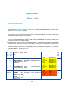
6.1 AlertsLog................................................... 38
6.2 AlarmsandWarnings ............................................ 38
6.2.1 AlertMessages............................................ 39
6.2.2 AlertIndicators............................................ 39
6.3 PowerFailure................................................. 40
2

6.3.1 InputDataControl .......................................... 40
6.3.2 Steering Gear / Thruster Control Failure . . . . . . . . . . . . . . . . . . . . . . . . . . . . . . 40
7 Hardware 41
7.1 MainComponents .............................................. 41
7.1.1 APH-7ControlPanel......................................... 41
7.1.2 APH-5ControlPanel......................................... 41
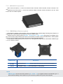
7.1.3 MCU/ACUControlUnit ....................................... 42
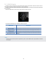
7.1.4 SMS-B Mode Selector (option) . . . . . . . . . . . . . . . . . . . . . . . . . . . . . . . . . . . 42
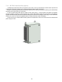
7.1.5 LVR-NF-AP(option) ......................................... 43
7.1.6 IB-TCS-2 Interface Box (option) . . . . . . . . . . . . . . . . . . . . . . . . . . . . . . . . . . 44
7.2 DataSources................................................. 45
7.2.1 Compass ............................................... 45
7.2.2 Rate-of-Turn ............................................. 45
7.2.3 WaterSpeedLOG .......................................... 45
7.2.4 GPSReceiver ............................................ 45
7.2.5 WindSensor ............................................. 45
7.2.6 INSSensor(WorkwithINS)..................................... 45
7.2.7 TrackControlSystem ........................................ 46
7.2.8 RudderFeedbackUnit........................................ 46
7.3 DataSentOut ................................................ 47
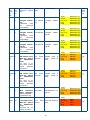
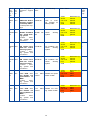
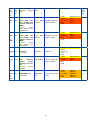
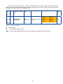
A Alert List 48
B Structure Diagram 74
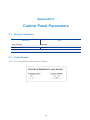
C Control Panel Parameters 75
C.1 DisplayParameters ............................................. 75
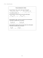
C.2 PanelSounds................................................. 75
C.2.1 Pressing Buttons and Control Transfer . . . . . . . . . . . . . . . . . . . . . . . . . . . . . . . 75
C.2.2 AlertSounds ............................................. 76
D Operating Conditions 77
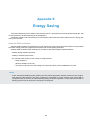
E Energy Saving 78
E.1 Power Consumption Calculation . . . . . . . . . . . . . . . . . . . . . . . . . . . . . . . . . . . . . . 79
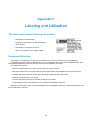
F Labeling and Utilization 80
3

Abbreviations
AC Alternating current
ACK Acknowledge
ADC Analog to digital converter
AP Autopilot
APM Controller module for main control unit
APP Controller module for all control units except
main control unit
AUTO Automatic (Heading Control mode)
BAM Bridge Alert Management
CALC Calculated value (“C” in some fields)
CAM Central Alert Management
COG Course over ground
COM Serial data port
CU Control Unit
DC Direct Current
ECDIS Electronic chart display and information system
ECS Electronic chart systems
EEPROM Electrically Erasable Programmable Read-
Only Memory (PCB)
FFU Full-Follow-Up
GPS Global Positioning system
HCS Heading Control System
HDG Heading
IMO International Maritime Organization
INS Integrated navigational system
JP Joystick Pilot System
MAGN Magnetic Compass (NMEA sensor)
MAS Mandatory Alarm System
NFU Non-Follow-Up
RAD Steering Radius
RFU Rudder Feedback Unit
ROT Rate of turn
SG Steering Gear
SMS Steering Mode Selector
SOG Speed over ground
SS Steering System
STW Speed through water
TCS Track Control System
THD Transmitting Heading Device
WP Way Point
4

Chapter 1
Introduction
1.1 General
•The Autopilot is designed to control displacement-type ships and high-speed crafts in the open sea. “Fail-
to-safety” principle is implemented in the Autopilot design, i.e. any failure leads to the least critical of any
possible new conditions.
•Navis NavAP is easy to install and maintain on the vessel. However, AP is a sophisticated electronic device,
which performance affected by sea conditions, hull shape and size, vessel speed.
•Navis NavAP main control station should be installed in the wheelhouse. Network AP stations (up to 5 units)
can be installed on the wings (indoor installation by default). Some AP units can be installed near the Steering
Gear / Steering System compartment.
•Navis NavAP Heading control system can be an integrated part of the Navis NJoy Advanced Joystick control
system in case of ordering and delivery of NJoy system to the Customer.
•Please read this Manual thoroughly prior to start operating Navis NavAP Heading control system.
WARNING
Autopilot is a very useful navigational aid, but it does not replace a human navigator under any circumstances.
Do not use automatic steering in the following conditions:
•In heavy traffic areas or in narrow waters
•In poor visibility or extreme sea conditions;
•When in areas where use of Autopilot is prohibited by the law.
When using Autopilot:
•Do not leave the helm unattended;
•Do not place any magnetic material or equipment near heading sensor used in the Autopilot system;
•Verify at regular intervals course and position of the vessel;
•Always switch to Standby mode in due time to avoid hazardous situations
5

1.2 Compliance
Heading control system hereinafter referred to as the Autopilot has DNV type examination for the compliance
with:
•IMO Res. A.342 (IX)
•IMO Res. MSC. 64(67) Annex 3
•IMO Res. A694 (17)
Autopilot is also compliant with:
•IMO Res. A.822 (19) and ISO11674 (2019) /16329 (2003) for High Speed Crafts
•IEC 62065 ed2 Track Control System
•IEC 62288:2014 Presentation of navigation-related information on shipborne navigational displays
•IEC62923 ed1.0(2018)
•DNV Rules for Classification of Ships (additional requirements NAUT-AW notation)
6

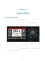
Chapter 2
Control Panel
2.1 APH-7 Control Panel
7

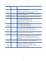
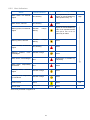
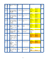
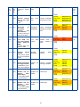
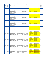
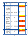
2.1.1 Buttons
Button View Name Function
Menu
Used to enter into user “Mode Menu”, which enables changing of the
Navis NavAP operating parameters.
Single press the button to enter into Quick menu “Parameters”.
Long press the button to enter into Extended menu.
Track
Used for immediate change-over into “Track” Heading control mode
from the current autopilot mode.
Auto HDG
Used for immediate change-over into “Auto” Heading control mode
from the current autopilot mode.
ROT/RAD
Used to change a “Steering by” method and its operational parame-
ters (“SET ROT” or “SET RAD”) using knob.
Single press the button to change the value.
Long press the button to change the “Steering by” parameter be-
tween “SET ROT” or “SET RAD”.
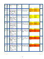
Mode
Used to select the required control mode.
Press the button single or several times to select the new control
mode. Then press knob to confirm choice.
Alarm ACK
Used for alert acknowledgement and scrolling.
Single press the button to acknowledge an active alert.
Press the button several times to scroll all active alerts in the list.
Long press the button to enter into “Alarm Settings”.
Cancel Used for immediate switch to the initial screen.
Dim Mode
Used for dimming LEDs and Display.
Press the button and rotate the knob clockwise to increase the high-
light level and rotate counterclockwise to decrease the level.
Long press the button to switch from Night mode to Dusk mode and
to Day mode.
In Control Used to transfer control (for the network configuration only).
Rotary knob
Turning knob clockwise changes heading/rudder angle order to the
right (Stbd), counterclockwise — to the left (Port).
Knob tilt left/right switches Info field, up/down — ignored.
Knob also has a pushbutton, which is used for confirmation new set-
ting of heading and other functions.
8

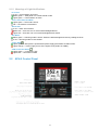
2.1.2 Meanings of Light Notifications
In Control
Is off — Control station is inactive
Blinks green — APH panel is in control transfer mode
Lights green — Control station is active
Track, Auto HDG, ROT/RAD
Lights green — the mode is active
Off — the mode is not activated
Alarm ACK
Is off — there are no alarms
Blinks red — there are one or more unacknowledged alarms
Lights red — there are one or more acknowledged active alarms
Dim Mode
Blinks green — Dimming mode is active. Select the desired brightness level by rotating the knob
Is off — Dimming mode is not activated
Power State
Lights green — APH panel is powered and power supply parameters are within limits
Lights orange — Power supply at one of the inputs is lost (PWR1 or PWR2)
CAN Connection State
Lights green — connection is OK
Lights red — connection is failed
2.2 APH-5 Control Panel
9

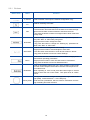
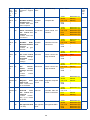
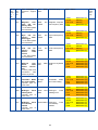
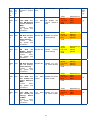
2.2.1 Buttons
Button View Name Function
In Control Used to transfer control (for the network configuration only).
Fn Used for switching “Info Field”.
Dim
Used for dimming LEDs and Display.
Press the button and rotate the knob clockwise to increase the high-
light level and rotate counterclockwise to decrease the level.
Long press the button to switch from Night mode to Dusk mode and
to Day mode.
ROT/RAD
Used to change a “Steering by” method and its operational parame-
ters (“SET ROT” or “SET RAD”) using knob.
Single press the button change the value.
Long press the button to change the “Steering by” parameter be-
tween “SET ROT” or “SET RAD”.
Alarm ACK
Used for alert acknowledgement and scrolling.
Single press the button to acknowledge an active alert.
Press the button several times to scroll all active alerts in the list.
Long press the button to enter into “Alarm Settings”.
Menu
Used to enter into user “Mode Menu”, which enables changing of the
Navis NavAP operating parameters.
Single press the button to enter into Quick menu “Parameters”.
Long press the button to enter into Extended menu.
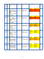
Mode/Auto
Used for immediate change-over into “Auto” Heading control mode
from the current autopilot mode and for selection of the required con-
trol mode as well.
When operating in “Auto” mode press the button single or several
times to select the new control mode. Then press knob to confirm
choice.
Rotary Knob
Turning knob clockwise changes heading/rudder angle order to the
right (Stbd), counterclockwise — to the left (Port).
Knob also has a pushbutton, which is used for confirmation new set-
ting of heading and other functions.
10

2.2.2 Meanings of Light Notifications
In Control
Is off — Control station is inactive
Blinks green — APH panel is in control transfer mode
Lights green — Control station is active
Alarm ACK
Is off — there are no alarms
Blinks red — there are one or more unacknowledged alarms
Lights red — there are one or more acknowledged active alarms
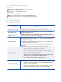
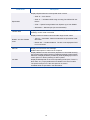
2.3 Panel Interface
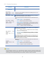
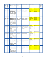
2.3.1 Field Descriptions
Field Name Description
Current control mode Displays the identification symbol of current operating mode
Set control mode Displays the name of selected operating mode. The field is displayed
during mode selection only.
Active/Locked Displays the panel status (Active/Locked). If the control panel is locked,
then “Key” symbol or “Locked” text is displayed.
Current Heading
Displays actual heading.
Set Heading and input resolution (1° or 1/10°) are shown below the
actual “Current Heading”.
Set Heading can be changed by turning knob: CW — increase, CCW
— decrease. Press knob to confirm.
Input resolution (1° or 1/10°) can be changed by long pressing knob (2
seconds).
Compass in use
Displays device type from which the actual heading is taken:
•GYRO1, GYRO2 — Gyrocompass 1/2 (NMEA)
•THD — True Heading Device (i.e. Satellite Compass, NMEA)
•MAGN — Magnetic compass (NMEA)
•HMS “ID1” — ID of the Master Compass from an external HMS
system (ID1 from incoming NMEA HMR sentences)
•INS — Integrated Navigational System (NMEA)
Steering by method
Displays Steering method in different control modes:
•SET ROT — Steering By Rate of Turn. Operating ROT value is
shown in degrees per minute
•SET RAD — Steering By Radius. Operating Radius value is
shown in nautical miles also used in “Track” control mode
11

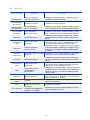
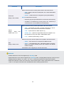
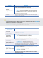
Field Name Description
Speed data
Displays Speed data source and speed value in knots:
•SOG: S — from Sensor
•SOG: C — calculated SOG using incoming GLL/GGA/VTG sen-
tences
•STW — Speed Through Water from Speed Log or from ECDIS
•SPD MAN — Manual input (not recommended)
Thruster data Displays the direction and force of tunnel thruster(s), when “Low Speed
Heading” control mode is activated
Rudder and Set Rudder
scale
Displays values of rudder order and rudder angle as bar charts.
•Top bar — Set rudder. Red mark indicates the operational “Rud-
der Limits”.
•Bottom bar — Rudder feedback. The bar is not displayed if RFU
is not connected
Alert bar Displays current active alert message.
Detailed descriptions of alerts see in Chapter 6.
Info field
Displays different sensor information (depends on connected sensors),
Track control data, HDG monitoring in different autopilot control modes.
Selection of displayed data is provided by knob tilt (left/right) on APH-7
control panel / Fn button pressing on APH-5 panel.
Displayed data depend on the current operating mode (Auto, Track, Fu,
River Pilot, etc.). Empty default bar is available in all control modes.
The spinner always runs if the APH panel is not frozen.
Available fields are specified in the table below.
12

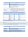
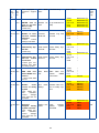
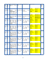
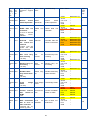
2.3.2 Info Field
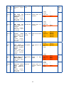
Info Field Name Example Description
Ship position
LAT 24° 54.2466’ N
LON 049° 42.1009’ E
Available in all control modes, if position source is
available from GPS or ECDIS
COG-SOG data
and its type
COG 325.0°
SOG 07.2 kn SENS
Available in all control modes, if COG/SOG data is
available from GPS or ECDIS
Relative Wind
data and its type
REL WIND 003° P
SPD 10.1 kn SENS
Available in all control modes excepting “Wind
Vane”, if Wind Sensor is connected to Navis NavAP
True Wind data
and its type
TRUE WIND 020°
SPD 01.2 kn CALC
Available in all control modes excepting “Wind
Vane”, if Wind Sensor is connected to Navis NavAP
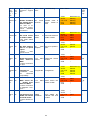
HDG Error HDG ERROR 000.1° →
Available in “Auto” Heading control mode. HDG er-
ror and its direction to Actual Heading value are dis-
played
Previously set
HDG
PREVIOUSLY SET
HDG 268.1°
Available in “Auto” Heading control mode. Pre-
vious “SET HDG” value is displayed during knob
movement (to set a new commanded HDG)
Way point
WP001 BTW 085.2°
DTW 12.15 NM
Available in “Auto”, “CTS Pilot” and “Track” control
modes if WP data is available from ECDIS or GPS
from the incoming NMEA sentences APB and BWC
(or BWR)
New WP.
Confirm Turn
BTW 085.2° DTW 12.15 NM
CHG 149° →
Available in “Track” control mode only, during WP
changing in the external ECDIS/ECS system
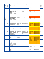
COG Error COG ERROR 002.5° →
Available in “CTS Pilot” control mode. COG keep-
ing error and direction to actual COG value are dis-
played
Previously set
COG
PREVIOUSLY SET
COG 270.0°
Available in “CTS Pilot” control mode. Previous
“SET COG” value is displayed during knob move-
ment (to set a new commanded COG)
HMS
HMS GYRO1 350.6°
GYRO2 350.6°
DELTA 000.0°
Available in all control modes, if more than one
Heading source is connected to Navis NavAP or
Heading Source is the external Heading Monitor
System (HMS)
Route Leg ROUTE LEG 268.1°
Available in “Track” (Ti) control mode only, when
TCS Category C is adjusted in the Installation
Menu as “ExtTRS” or “ExtHTC”
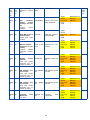
Curves CURVE1 Available when “Curves” (custom function) was or-
dered and configured
Drift DRIFT 90.0° (T) 0.9 kn Available when NMEA sentences received from
navigational equipment
Gyro Correction
HDG 297.3°
CORRECTION ADDED 0.2°
(SPD/LAT + DYNAMIC)
Available when receiving HCR (Heading correction
report) messages from Gyro
13

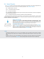
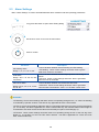
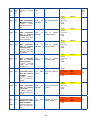
2.4 Control Transfer
The In Control button is used for the network control transfer and operating in the network configuration only.
The following control transfer methods are available (adjustable in the Installation Menu):
•Def — default method, see below;
•Conv — conventional method, see below;
•Off — for single control station;
•DI — the method is provided by discrete input of the APH panel and reserved for enhanced configuration
with hardwired station selector;
•Ext — for logically linked joystick controller, reserved for joystick configurations.
When Navis NavAP includes several control panels, only one is active (in control) at the time. The rest control
panels are disabled for vessel control (locked), i.e. buttons and knobs are inactive and “Key” symbols are shown
in Active/Locked fields on these displays.
Default control transfer
Press the In Control button on any network locked panel. The previous active control
panel becomes locked, i.e. buttons and knob are inactive (excepting “Menu”, “Dim
Mode” and “Alarm ACK” buttons). The previous active control panel generates time
limited audible signal and displays warning message “Control Transfer”.
Conventional control transfer
At first perform “Give” function from the current active station by pressing its In Control
button. In Control buttons on all locked panels start blinking by their green LEDs
and “Key” symbol is also presented on all locked panels. Next step is to confirm the
selection of the new station by pressing In Control button.
NOTE
•If parameter “Appointed St” set as “P HS” in the Installation menu, this station becomes active by default
after switching to “Auto HDG” mode. Otherwise, the latest active station remains in control in any control
mode.
•If station is named as “P HS” in the Installation menu (arranged as main helm’s station) and control transfer
is set as “Conv” (Conventional), In Control button pressing makes P HS station active unconditionally.
14

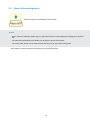
2.5 Alarm Acknowledgement
Press the button to acknowledge incoming alarm
NOTES
•When a failure is detected, audible signal is generated and the corresponding alert is displayed in the Alert
bar.
•The alarm acknowledgement is available only through the active control panel.
•The “Alarm ACK” button can be used for alarm silencing only at any locked control panel.
See Chapter 6 for alert indicators and Appendix A for alert descriptions.
15

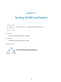
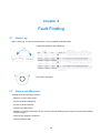
Chapter 3
Turning On/Off and Restart
Set mode selector to off position and select Standby mode
Turning On
•Turn On main power supply PWR1 and PWR2
Turning Off
•Turn Off main power supply PWR1 and PWR2
Software Reset
Long press buttons to reboot all controllers.
It will not cause restart of APH operating system.
16

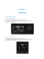
Chapter 4
Operational Modes
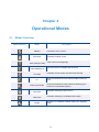
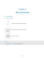
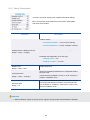
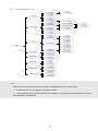
4.1 Modes Overview
Mode Indication Mode Description
Standby Auto Pilot is not in control
Auto HDG Automatic heading control
Track (Category A/B) Track control on straight legs
Track (Category C) Full track control on straight legs and turns
CTS Pilot Automatic Course control (Course-Over-Ground)
Fu
Short-term switchover to the manual rudder control via
knob
Follow-up Override
Short-term switchover to the manual FU steering by ex-
ternal FFU override tiller (option)
River Pilot Automatic steering by Rate-Of-Turn
Wind vane Automatic steering by set Relative Wind angle
Dodge
Avoidance of obstacles without leaving the autopilot
mode
17

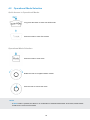
4.2 Operational Mode Selection
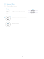
Quick Access to Operational Modes
Long press the button to enter Auto HDG mode
Press the button to enter Track mode
Operational Mode Selection
Press the button to view mode
Rotate the knob to navigate between modes
Push the knob to choose the mode
NOTE
•If Mode button is pressed, but there is no confirmation of selected mode within 20 seconds, Navis NavAP
remains in the current control mode.
18

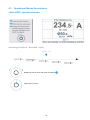
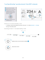
4.3 Operational Modes Descriptions
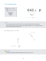
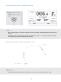
“Auto HDG” operational mode
Operating principle of “Auto HDG” mode
Rotate the knob to set a new value of heading
Push knob to confirm
19
Page is loading ...
Page is loading ...
Page is loading ...
Page is loading ...
Page is loading ...
Page is loading ...
Page is loading ...
Page is loading ...
Page is loading ...
Page is loading ...
Page is loading ...
Page is loading ...
Page is loading ...
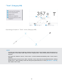
Page is loading ...
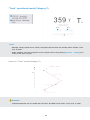
Page is loading ...
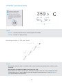
Page is loading ...
Page is loading ...
Page is loading ...
Page is loading ...
Page is loading ...
Page is loading ...
Page is loading ...
Page is loading ...
Page is loading ...
Page is loading ...
Page is loading ...
Page is loading ...
Page is loading ...
Page is loading ...
Page is loading ...
Page is loading ...
Page is loading ...
Page is loading ...
Page is loading ...
Page is loading ...
Page is loading ...
Page is loading ...
Page is loading ...
Page is loading ...
Page is loading ...
Page is loading ...
Page is loading ...
Page is loading ...
Page is loading ...
Page is loading ...
Page is loading ...
Page is loading ...
Page is loading ...
Page is loading ...
Page is loading ...
Page is loading ...
Page is loading ...
Page is loading ...
Page is loading ...
Page is loading ...
Page is loading ...
Page is loading ...
Page is loading ...
Page is loading ...
Page is loading ...
Page is loading ...
Page is loading ...
Page is loading ...
Page is loading ...
-
 1
1
-
 2
2
-
 3
3
-
 4
4
-
 5
5
-
 6
6
-
 7
7
-
 8
8
-
 9
9
-
 10
10
-
 11
11
-
 12
12
-
 13
13
-
 14
14
-
 15
15
-
 16
16
-
 17
17
-
 18
18
-
 19
19
-
 20
20
-
 21
21
-
 22
22
-
 23
23
-
 24
24
-
 25
25
-
 26
26
-
 27
27
-
 28
28
-
 29
29
-
 30
30
-
 31
31
-
 32
32
-
 33
33
-
 34
34
-
 35
35
-
 36
36
-
 37
37
-
 38
38
-
 39
39
-
 40
40
-
 41
41
-
 42
42
-
 43
43
-
 44
44
-
 45
45
-
 46
46
-
 47
47
-
 48
48
-
 49
49
-
 50
50
-
 51
51
-
 52
52
-
 53
53
-
 54
54
-
 55
55
-
 56
56
-
 57
57
-
 58
58
-
 59
59
-
 60
60
-
 61
61
-
 62
62
-
 63
63
-
 64
64
-
 65
65
-
 66
66
-
 67
67
-
 68
68
-
 69
69
-
 70
70
-
 71
71
-
 72
72
-
 73
73
-
 74
74
-
 75
75
-
 76
76
-
 77
77
-
 78
78
-
 79
79
-
 80
80
-
 81
81
-
 82
82
-
 83
83
-
 84
84


Alphatron Marine AlphaPilot MFM Owner's manual
- Type
- Owner's manual
- This manual is also suitable for
Ask a question and I''ll find the answer in the document
Finding information in a document is now easier with AI
Related papers

Other documents
-
Simrad AP70/AP80 User manual
-
Raytheon Autopilot NP 5000 Series, Autopilot Operator Unit AS 102-890 Operating instructions
-
-
-
-
Furuno FMD3300 User manual
-
Furuno FMD-3300 User manual
-
-
-