Page is loading ...

INSTALLATION MANUAL
UltraGRIND Package System with
Float Switches
Form No. 088314-Rev. D
IMPORTANT: Read all instructions in this manual before operating pump.
As a result of Crane Pumps & Systems, Inc., constant product improvement program, product
changes may occur. As such Crane Pumps & Systems, Inc., reserves the right to change product
without prior written notification.
420 Third Street/P.O. Box 603 83 West Drive, Brampton
Piqua, Ohio 45356-0603 Ontario, Canada L6T 2J6
Phone: (937) 778-8947 Phone: (905) 457-6223
Fax: (937) 773-7157 Fax: (905) 457-2650
www.cranepumps.com
A Crane Co. Company
PUMPS & SYSTEMS

TABLE OF CONTENTS
USER GUIDE ....................................................................................................................... 3
SAFETY FIRST..................................................................................................................... 4
A. GENERAL INFORMATION
(Receiving, Storage, Service Centers, Unpacking, Location) ............................................... 5
B. INSTALLATION
(Bedding, Gravel Specifications, Placing into Hole) (Fig. 1, 2 & 3)....................................... 5 - 6
(Locating and Installing Inlet) (Fig. 4, 5, 6 & 7) ..................................................................... 6 - 7
(Discharge) (Fig. 8) ............................................................................................................... 7
(Incoming Cable Location) (Fig. 9 10 & 11) .......................................................................... 8 - 9
(Backfill) (Fig 12)................................................................................................................... 9
(Pump Installation) (Fig. 13 & 14) ......................................................................................... 9
(Junction Box Connections, Direct Burial Cable, Level Controls) (Fig. 15) ........................... 10 - 11
(Winterization)....................................................................................................................... 11
(Junction Box Table) ............................................................................................................. 12
C. REPLACEMENT PARTS ...................................................................................................... 11
JUNCTION BOX WIRING:
SGV Simplex w/Temp- 200-230V, 1Ph & 200-230/460V, 3Ph (Fig. 16).............................. 13
SGV Simplex w/Moist & Temp. - 200-230V, 1Ph & 200-230/460V, 3Ph (Fig. 17) ................ 14
SGV Simplex w/Temp. 5HP- 200-230V, 1Ph (Fig. 18) ......................................................... 15
SGV Simplex w/Moist & Temp. 5HP- 200-230V, 1Ph (Fig. 19) ............................................ 16
SGV Duplex-200-230V, 1Ph & 200-230/460V, 3Ph (Fig. 20) ............................................... 17
SGPC Simplex - 115-230V, 1Ph (Fig. 21) ............................................................................ 18
SGPC Duplex - 115-230V, 1Ph (Fig. 22) .............................................................................. 19
EXPLODED VIEW - SIMPLEX ............................................................................................. 20
PARTS LIST - SIMPLEX....................................................................................................... 21 - 22
EXPLODED VIEW - DUPLEX............................................................................................... 23
PARTS LIST - DUPLEX........................................................................................................ 24 - 26
DIRECT BURIAL CABLE REQUIREMENTS ........................................................................ 27
BASIN VOLUME CHART...................................................................................................... 28
BASIN BALLAST REQUIREMENTS .................................................................................... 29
RETURNED GOODS POLICY .................................................................................................... 30
WARRANTY
Other brand and product names are trademarks or registered trademarks of their respective holders.
UltraGRIND is a trademark of Barnes Pumps, Inc.
® Barnes is a registered trademark of Barnes Pumps, Inc.
© Barnes Pumps, Inc. 1993, 2000, 2002 Alteration Rights Reserved. Printed in U.S.A.
2

USER GUIDE
Congratulations on
your purchase of a
Barnes UltraGRIND grinder pump system.
With proper care and by following a few
simple guidelines your grinder pump will give
you many years of dependable service.
Use and Care
The UltraGRIND grinder pump station is
designed to handle routine, domestic
sewage. Solid waste materials should be
thrown in the trash. While your station is
capable of accepting and pumping a wide
range of materials, regulatory agencies
advise that the following items should not be
introduced into any sewer either directly or
through a kitchen waste disposal:
•Glass
•Metal
•Diapers
•Socks, rags or cloth
•Plastic objects (e.g., toys, utensils, etc.)
•Sanitary napkins or tampons
In addition you must NEVER introduce into
any sewer:
•Explosives
•Flammable Material
•Lubricating Oil and/or Grease
•Strong Chemicals
•Gasoline
General Information
Your home wastewater disposal service is
part of a low pressure sewer system. The key
element in this system is the Barnes
UltraGRIND grinder pump station. The basin
collects all wastewater from the house. The
solids in the sewage are then ground to a
small size suitable for pumping in the slurry.
The grinder pump
generates sufficient
pressure to pump
this slurry from your home to the wastewater
plant.
Power Failure
Your grinder pump cannot dispose of
wastewater or provide an alarm signal without
electrical power. If electrical power service is
interrupted, keep water usage to a minimum.
Warranty
Your grinder pump is furnished with a
warranty against defects in material or
workmanship. A properly completed Start
Up/Warranty Registration form must be on file
at the Barnes factory in order to activate your
warranty. In addition your pump must be
installed in accordance with the installation
instructions.
If you have a claim under the provisions of the
warranty, contact your local Barnes Pumps,
Inc. Distributor.
When contacting your representative for
service, please include your station serial
number, pump model number, and pump
serial number.
For future reference, record the following
information:
Station Serial No:
Pump Model No:
Pump Serial No:
Local Distributor:
Distributor Telephone:
3

SAFETY FIRST!
PLEASE READ THIS BEFORE INSTALLING
OR OPERATING PUMP.
GENERAL
1. Most accidents can be avoided by using COMMON SENSE.
2. Read this operation and maintenance instruction manual.
3. Do not wear loose clothing that may become entangled in the impeller or other moving parts.
4. Always wear appropriate safety gear, such as safety glasses, when working on the pump or piping.
5. Bronze/brass and bronze/brass fitted pumps may contain lead levels higher than considered safe for potable water systems.
Various government agencies have determined that leaded copper alloys should not be used in potable water applications.
For non-leaded copper alloy materials of construction, please contact factory.
6. Minimize the amount of cooking grease entering the system.
7. Do Not leave pump cover off the basin, except while servicing, to prevent entrance of foreign materials such as rocks, metal,
soil, animals or humans.
8. Prevent large articles of clothing, large amounts of chemicals, other materials or substances such as are uncommon in
domestic sewage from entering the system.
9. During power black-outs, discontinue water consumption at the home(s) to prevent sewage from backing up into the house.
10. Prevent infiltration or direct flow of rain or run-off water into the pump basin to minimize pump cycling. This will prevent
overloading the treatment facility, and will facilitate swift transportation of sewage.
11. Always keep the shut-off valve completely open when system is in operation (unless advised otherwise by the proper authorities).
12. Keep the control panel locked or confined to prevent unauthorized access to it.
13. If the pump is idle for long periods of time, it is advisable to start the pump occasionally by adding water to the basin.
14. Before removing the pump from the basin, be sure to close the shut-off valve. (This prevents backflow from the pressure sewer.)
15. Make sure level controls are provided at time of installation.
PUMPS
16. Recommended no more than 10 starts per hour.
17. Pumps build up heat and pressure during operation-allow time for pumps to cool before handling or servicing.
18. Only qualified personnel should install, operate and repair pump.
19. Keep clear of suction and discharge openings. DO NOT insert fingers in pump with power connected.
20. Do not pump hazardous materials (flammable, caustic, etc.) unless the pump is specifically designed and designated to handle
them.
21. Do not block or restrict discharge hose, as discharge hose may whip under pressure.
22. Make sure lifting handles are securely fastened each time before lifting.
23. Do not lift pump by the power cord.
24. Do not exceed manufacturers recommendation for maximum performance, as this could cause the motor to overheat.
25. Secure the pump in its operating position so it can not tip over, fall or slide.
26. Keep hands and feet away from impeller when power is connected.
27. Submersible Pumps are not approved for use in swimming pools, recreational water installations, decorative fountains or any
installation where human contact with the pumped fluid is common.
28. Do not operate pump without safety devices in place.
29. Always replace safety devices that have been removed during service or repair.
ELECTRICAL
30. To reduce risk of electrical shock, pump must be properly grounded in accordance with the National Electric Code (NEC) and all
applicable state and local codes and ordinances.
31. To reduce risk of electrical shock, always disconnect the pump from the power source before handling or servicing. Lock out
power and tag.
32. Any wiring of pumps should be performed by a qualified electrician.
33. Never operate a pump with a power cord that has frayed or brittle insulation.
34. Cable should be protected at all times to avoid punctures, cut, bruises and abrasions - inspect frequently.
35. Never handle connected power cords with wet hands.
36. Do not remove cord and strain relief. Do not connect conduit to pump.
37. To reduce risk of electrical shock, all wiring and junction connections should be made per the NEC and applicable state
and local codes. Requirements may vary depending on usage and location. See wiring diagrams in manual.
38. Do Not operate the pump in the "HAND" control position and leave the pump unattended.
IMPORTANT! BARNES® PUMPS, INC. IS NOT RESPONSIBLE FOR LOSSES, INJURY, OR DEATH RESULTING FROM A
FAILURE TO OBSERVE THESE SAFETY PRECAUTIONS, MISUSE OR ABUSE OF PUMPS OR EQUIPMENT.
4

SECTION A: GENERAL INFORMATION
A-1) RECEIVING:
Upon receiving the Basin Package System, it should be
inspected for damage or shortages. If damage has occurred,
file a claim immediately with the company that delivered
the basin package.
A-2) STORAGE:
If Basin Packages are going to be stored make sure all outside
openings are sealed, i.e., discharge coupling, electrical
coupling (if equipped), etc., also secure access door or basin
cover.
A-3) SERVICE CENTERS:
For the location of the nearest Barnes® Pumps Service Center,
check your catalog, your Barnes Pumps, Inc. representative or
Barnes Pumps, Inc. Service Department in Piqua, Ohio,
telephone (937) 778-8947.
A-4) UNPACKAGING:
Before installing Basin Package remove the tape from all
outside openings, discharge coupling, electrical inlet (if
equipped), etc. Remove basin cover on simplex or open access
door on duplex units being careful not to damage gasket, to
unpackage anything that was secured for shipment.
A-5) LOCATION:
This basin system is intended for use with water, sewage and
effluent applications. The standard basin is vented. Any
alterations from the standard must be in accordance with local
codes. This basin system is not to be installed in locations in
which the basin interior would be classified as a HAZARDOUS
location in accordance with NEC ANSI/NFPA 70.
SECTION B: INSTALLATION
B-1) BEDDING:
Prepare the hole to the proper depth. Add and level bedding of
sand, select aggregate (pea gravel - See Gravel Specifications)
of 4 to 6 inches or concrete pad or a concrete donut shall be
laid before basin is lowered into the ground. The aggregate
must conform to the bottom of the basin and reach a
compaction of 85% Standard Proctor Density. See Figure 1.
GRAVEL SPECIFICATION:
1. A naturally rounded aggregate is required, clean and
free flowing with particle size not less than 1/8" or
more than 3/4" in diameter. Use this description when
specifying or ordering because material is known by
different names in different areas. This material is
commonly called pea gravel.
2. Stone or gravel crushing with angular particle size not
less than 1/8" or more than 1/2" diameter washed and
free flowing is acceptable as an alternate material.
This material must meet ASTM C-33 paragraph 9.1
requirements for quality and soundness.
B-2) PLACING STATION INTO HOLE:
Lifting the basin system into place be done with a cloth or nylon
type strap around basin or by a lifting harness connected to
eyebolts that are set into the concrete pad that is connected to
basin by anchor bolts. Never use chain or cable type lifting
device around outer basin. This can and may create a fracture
in the fiberglass, See Figures 2 and 3.
Lower the basin, centering it into the hole and orient it to allow
for proper inlet installation. A minimum clearance of 4 to 6
inches should be maintained between the tank wall and the
surrounding earth. ALL OSHA PROCEDURES SHOULD BE
FOLLOWED REGARDING INSTALLATION OF BASIN. The
basin must be leveled after placement to within 1/2 bubble. To
prevent the basin from floating upward when the ground water
is high, a weight of 63 pounds per cubic foot of basin volume
must anchor the basin in place (see "BALLAST
REQUIREMENTS" on page 29). This can be done by fastening
the ballast support flange to a concrete pad or donut, or by
adding the equivalent amount of gravel and/or concrete to the
surrounding basin area (surrounding the 2" flange).
Figure 1
Figure 2
5

B-3) LOCATING & INSTALLING INLET:
B-3.1) FLEXIBLE PIPE FITTING INLET:
The flexible pipe fitting for the inlet must be installed.
1. Find the location where the center of the coupling will
be positioned on basin. See Fig. 5 for recommended
location.
2. Using a HOLE SAW, cut the hole in the basin
(DO NOT use a Saber Saw). Refer to the chart below
for hole size.
3. Install flexible pipe fitting in the opening. See Figure 4.
FLEXIBLE PIPE
FITTING SIZE
HOLE
SIZE
COLOR
CODE
1-1/4"
1-1/2"
2"
3" Black-40
Black/Red-40
Black/Blue-40
3" 4" White-40
4" 5" Grey-40, Maroon-35
6" 7" Black-40, Yellow-35
NOTE: Schedule 40 and SDR35 pipe require different sizes of
flexible pipe fittings. Check to be sure the inlet pipe matches
the flexible pipe fitting supplied.
To install the inlet pipe into the flexible pipe fitting, chamfer the
end and lube the pipe with soapy water for ease of installation,
see Figure 4. An OPTIONAL Adapter or Caulking hub may be
used in place of the flexible pipe fitting. (see Sections B-3.2 and
B-3.3).
TABLE For FIGURE 5
24" - 30" DIA
Simplex Basin
Angle "A" Should Be
Between 30° - 60°
36" And Larger Simplex And
All Duplex Basins
Angle "B" Should Be 45°
Maximum.
B-3.2) FLANGE ADAPTER INLET (OPTIONAL):
The plastic flange adapters are used with schedule 40 pipe,
to install (see Figure 6).
1. Find the location where the center of the coupling will
be positioned on basin. Consult specifications for this
location.
2. Using a HOLE SAW, cut the hole in the basin to
accept the back (the portion that will be going inside
the basin), outside diameter of the flange adapter.
3. Place flange adapter on basin wall and drill mounting
holes in basin wall to match flange adapter base.
4. Apply gasket or sealing caulk to back of plate, and mount
plate on basin.
5. Insert bolts, washers and nuts through basin wall into
adapter base, and tighten.
6. Remove flange and o-ring from adapter and place
over pipe.
7. Insert pipe through base and align flange to bolts on base.
8. Tighten bolts for seal.
Figure 3
Figure 4
Figure 5
6

B-3.3) CAULKING HUB INLET, (OPTIONAL):
The hubs can be used with schedule 40 pipe, to install, (See
Figure 7)
1. First locate where the inlet will be. Consult
specifications for this location.
2. Using a HOLE SAW, cut the hole in the basin to the
inside diameter of the hub.
3. Place hub on basin wall and drill mounting holes in
basin.
4. Apply gasket to back of hub, and mount hub on basin.
5. Insert bolts, washers and nuts through basin wall and
hub, and tighten.
6. Insert pipe into hub and caulk.
B-3.4) Discharge:
Connect the sanitary main to the NPT discharge connection
located on the outside of the basin (see Figure 8). It is required
that a shut-off valve, and a redundant check valve, be located
at the property line near the sanitary main (by others). A flexible
pipe coupling (Optional or ordered separately), should also be
installed at the basin. The check valve should be of a flap style
able to operate in a horizontal position. It is recommended that
in cold regions the piping above the frost grade be insulated.
Consult factory for severely cold climates.
B-3.5) Control Panel:
Next locate and mount electrical control panel, and run cable
to the basin package (see Control Panel Manual).
CAUTION !
ALL MODEL PUMPS AND CONTROL PANELS MUST
BE PROPERLY CONNECTED AND PROPERLY
GROUNDED PER THE NATIONAL ELECTRICAL CODE,
STATE, AND LOCAL CODES. IMPROPER GROUNDING
VOIDS WARRANTY.
NOTE: A proper motor controller must be provided that is
compatible with the pump (s) being installed. (Motor Controller
is part of control panel when factory supplied.)
Figure 6
OPTIONAL Flange Adapter:
Figure 7
OPTIONAL Caulking Hub: Figure 8
7

B-4) INCOMING CABLE LOCATION:
For installations using a cover & J-Box go to Section B-4.1.
For installations using the combination cover go to Section
B-4.3.
B-4.1) Direct Burial Cable with Cable Grips
(Cover with J-Box):
Backfill and compact to a convenient level to work around top
of basin. Locate and drill holes (see page 27 for hole sizes)
for the Direct Burial cable grips in the basin wall. Holes should
be located at least 18 inches below grade. Feed the direct
burial cable through the cable grips and into the junction box
and tighten the grips on the box and the basin. It is
important to leave enough cable slack between the
junction box and basin wall to allow the cover to be
removed (See Figure 9).
B-4.2) Direct Burial Cable with Conduit Coupling
(Cover with J-Box):
Backfill and compact to a convenient level to work around
top of basin. To install an OPTIONAL conduit coupling
(see Figure 10),
1. Find the location where the center of the coupling will
be positioned on basin.
2. Using a HOLE SAW, cut the hole in the basin to the
outside diameter of the coupling being installed.
3. Place coupling on basin wall and drill mounting holes
in basin.
4. Apply gasket or sealing caulk to back of coupling, and
mount coupling on basin.
5. Insert bolts, washers and nuts through basin wall and
coupling, and tighten.
After coupling has been installed, run the direct burial
cable through the coupling and into the junction box and
tighten the grips on the box. It is important to leave
enough cable slack between the junction box and
basin wall to allow the cover to be removed (See Figure
10). See Section B-7 for sealing of junction box.
B-4.3) Direct Burial Cable with Cable Grips
(Combination Cover):
Backfill and compact to a level comfortable to work around
basin. Remove cord grip located in parts common box,
shipped inside the basin. Make sure cable will fit and seal in
the cord grip prior to mounting in the basin. Drill a hole to size
specified in chart for your size cord grip supplied. The hole
should be located a minimum of 18 inches below grade or
per NEC and local codes. Install the grip with the cord grip
body inside the basin and the lock nut on the outside and
tighten locknut to 1/2 turn past hand tight. Feed the direct
burial cable through the grip and into the grommet assembly
labeled "DB" in the insert. Reference the label on top of the
control panel to locate the correct grip in the control panel to
put the wire into. Leave enough cable inside the panel to
reach all connection points. Tighten the grips leaving
enough slack between the basin wall and the insert to
remove the insert completely off the basin.
Figure 9
DIRECT BURIAL
CABLE
CABLE GRIPS
BASIN WALL
JUNCTION BOX
CABLE GRIPS
Figure 10
DIRECT
BURIAL
CABLE
CONDUIT
COUPLING
BASIN WALL
JUNCTION BOX
CABLE GRIPS
OPTIONAL Conduit Hub Installation:
Figure 11
CABLE GRIPS
CABLE GRIPS
CONVERTABLE
COVER INSERT
CONTROL
PANEL
8

B-4.4) Direct Burial Cable with Conduit Coupling
(Combination Cover):
Backfill and compact to a convenient level to work around
top of basin. To install an OPTIONAL conduit coupling (see
Figure 10 & 11).
1. Feed the cables up through the appropriate holes on
the new insert.
•The holes are labeled "DB" (Direct Burial Cable),
"PP" (Pump Power), "PC" (Pump Control - SGV Units Only)
and "LC" (Level Control).
•Make sure at this point, that all of the cables will be long
enough to reach their connection points in the panel while
still having enough room to remove the insert from
the basin.
2. Looking at the color-coded diagram on the lable
attached to the panel, slide the appropriate color-coded
friction ring, color-coded gromment, second color-coded
friction ring and gland nut over the cable. Loosely thread
the gland nut into the gland molded into the insert so that
the cable will still move in the assembly.
3. Feed the cord through the appropriate cord grip on the
control panel making sure that the rubber grommet is
installed in the grip.
•The cable jacket should be visible from inside the control
panel to insure that the grommet is not sealing on individual
wire strands.
•Care should be taken to make sure there are no slits or
damage on the cable jacket where the cord grip is sealing.
4. Tighten the control panel grips to 1/4 turn past hand tight
using a pair of channel locks. After tightening the grip,
make sure the retaining nut for the grip on the inside of
the panel is tight.
5. Tighten the gland nuts per the instructions on the
control panel label (3 turns past finger tight).
6. Reference the Control Panel manual for panel wiring
details.
After the coupling has been installed, run the direct burial cable
through the coupling and into the grommet labeled "DB" in the
insert. Reference the lable on top of the control panel to locate
the correct grip in the control panel to put the wire into. Leave
enough cable inside the panel to reach all connection
points. Tighten the grips leaving enough slack between
the basin wall and the insert to remove the insert completel
off the basin.
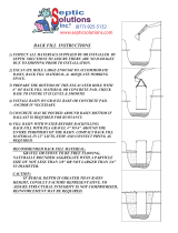
B-5) Backfill:
Finish backfill and compaction. (see Figure 12). Place at least
4 inches and preferably 6 inches of aggregate in layers around
the entire periphery of the basin in the ground, being careful
not to damage or loosen any connections.
CAUTION !
IN FREEZING CONDITIONS BACKFILL MUST BE DRY
AND FREE OF ICE.
DO NOT use backfill materials other than those specified
above. In areas where specified materials are not available
contact Barnes Pumps, Inc. for information on approved
alternate materials.
The basin warranty is automatically voided if other than
approved bed and backfill materials are employed without
advance written approval.
B-6) PUMP INSTALLATION:
First attach lifting rope or chain to the pump (See Figure 13).
Remove basin cover or open access door. Record Pump
Model, Part and Serial numbers in Start-Up manual and on
User Guide. Rotate pump impeller by hand and then lower
pump and movable assembly, utilizing the lifting chain or rope,
down the rail slowly, (DO NOT DROP)! Observe OSHA
recommendations when installing and removing pump.
CAUTION !
RISK OF ELECTRICAL SHOCK. DO NOT LOWER PUMP
BY THE POWER CORD.
Figure 12
Figure 13
Rope or Chain
9

NOTE: A hoist or crane may be used in lowering and removing
the pump. Center the pump under the hook so that the pump
can be lifted straight up. Lifting a pump that is not centered will
create side pulls which may strain the crane and/or cause the
pump to bind in the guide rail. Follow all general precautions in
the crane’s manual when installing and operating the crane.
See Figure 14.
B-7) JUNCTION BOX CONNECTIONS:
This section refers to basins having a cover with j-box. For
combination covers, see the "Control Panel Manual" and panel
schematics for proper wiring of control panel.
IMPORTANT !
CHECK TO BE CERTAIN THAT ALL POWER IS OFF.
IMPORTANT !
ALL CONNECTIONS INSIDE THIS TANK AND/OR
JUNCTION BOX MUST BE MADE WITH "UL" LISTED
WATER TIGHT CONNECTORS.
CAUTION !
THIS UNIT MAY HAVE MORE THAN ONE CONNECTION
TO THE SOURCE OF SUPPLY. TO REDUCE THE RISK
OF ELECTRIC SHOCK, DISCONNECT ALL SUCH
CONNECTIONS BEFORE SERVICING.
Wire Size: - Consult a qualified electrician for proper wire size.
See Pump Manual for electrical information.
Direct Burial Cable:
Due to the availability of multi conductor direct burial cables,
several options have been left to the installer (see "DIRECT
BURIAL CABLE REQUIREMENTS" on page 27).
For OPTIONAL conduit from the basin to the motor controller,
it is recommended that a packing material such as a sprayable
urethane foam be used in the conduit line, placed around the
wires, at the conduit coupling to help prevent gases from
entering the motor controller. Packing is recommended for ALL
entries into the motor control panel. It is very important to keep
the conduit line dry and free from moisture during this process.
Remove junction box cover to connect pump, sensor and
control cords to incoming direct burial cables. Refer to Figures
16 and 22 for your particular pump type and configuration.
NOTE: Figures 16 and 22 are for illustration purposes only,
cord locations, cables, color codes and junction box
design may vary.
B= Black, OR = Orange (or BL= Blue), R= Red,
G= Green, W=White.
To make wire connections, use the appropriate size wire nut.
B-8) LEVEL CONTROLS:
The level controls are to be supported by a float pole (or
optional cable rack) that is attached to the rail assembly. Floats
may be adjusted by loosening the cable ties on the float pole
(or by loosening the cord grips on the cable rack). Floats are
factory adjusted before shipment, re-adjustment may be
required for your particular installation.
IMPORTANT !
BOTTOM FLOAT FOR "OFF" OR "LOW LEVEL
ALARM", MUST BE A MIN. OF 10" FROM BOTTOM OF
BASIN TO WEIGHT ON SUSPENDED FLOAT, OR TO
CABLE TIE ON POLE MOUNTED FLOAT.
Be certain that the level controls cannot hang up or foul in it’s
swing .
Float Pilot Switch Rating: 4.5A @ 115 Volts, 1/2 HP.
2.2A @ 230 Volts, 1/2 HP.
NOTE: Float switch activates pump contactor only and does
not switch pump directly.
OPERATION SEQUENCES:
Three float switches are normally supplied with SGV simplex
systems and four withSGPC and duplex systems. For SGPC
stations the lowest switch is a "Redundant Off" and is wired in
series with the second switch, the "Normal Off" the third switch
is for PUMP ON and the fourth is ALARM ON. For SGV stations
the lowest switch is for PUMP(s) OFF, the next highest for
PUMP ON for simplex and LEAD PUMP ON for duplex, the
third at still higher level for ALARM ON for simplex and LAG
PUMP ON for duplex, and the fourth at the highest level for
ALARM ON for duplex systems.
The level controls are normally open, unless otherwise
specified. As the wet well level rises, the OFF float switch
closes. As level continues to rise, the lead ON switch closes,
completing the pilot circuit to start the lead pump. When the
lead pump lowers the level and the lead ON switch opens, no
action occurs due to a latching contact which keeps the circuit
energized until the level is lowered to the point at which the
pump OFF switch opens. The float switches are to be
connected to the pump control relay(s) in the pump motor
controller.
Figure 14
10

SECTION: C REPLACEMENT PARTS
C-1 ORDERING REPLACEMENT PARTS:
When ordering replacement parts, ALWAYS furnish the
following information:
1. Serial number and date code. (C-4)
2. Model number. (C-3)
3. Part number. (C-2)
4. Part description.
5. Item part number.
6. Quantity required.
7. Shipping instructions.
8. Billing instructions.
C-2 PART NUMBER:
The part number consists of a six (6) digit number, which
appears in the catalog. A one or two letter suffix may follow
this number to designate the design configuration. This
number is used for ordering and obtaining information.
C-3 MODEL NUMBER:
This designation consists of numbers and letters which
represent the diameter, depth and design. This number is
used for ordering and obtaining information.
C-4 SERIAL NUMBER:
The serial number block will consist of a six digit number,
which is specific to each unit and may be preceded by an
alpha character, which indicates the plant location. This
number will also be suffixed with a four digit number, which
indicates the date the unit was built (Date Code).
EXAMPLE: A012345 0490.
Reference the six digit portion (Serial Number) of this
number when referring to the product.
Figure 15
2
3
1
11

TABLE 2 - JUNCTION BOX - ITEM #29
PUMP MODEL PUMP &
CONTROL
CABLE SIZE
CONFIGURATION FIGURES PART N0.
(Valox)
SGV Grinders - Temp.
(Except 5002L & 5022L)
10/4 - 0.745
14/2 - 0.530
Replace DBC Power 1/2" -0 .375/0.437
with 1/2" - 0.437/0.500
Using Extra Grommet 077843V
16
20
104049-Simplex
094687-Duplex
SGV Grinders - Moist/Temp.
(Except 5002L & 5022L)
10/4 - 0.745
18/5 - 0.476
Replace DBC Power 1/2" -0 .375/0.437
with 1/2" - 0.437/0.500
Standard
17
20
104049-Simplex
094687-Duplex
SGV5002L &
SGV5022L
Temp.
6/4 - 1.010
8/4 - 0.780
14/2 - 0.530
Standard
Using Extra Grommet 077843V
18
20
102736-Simplex
095692-Duplex
SGV5002L &
SGV5022L
Moist/Temp.
6/4 - 1.010
8/4 - 0.780
18/5 - 0.476
Replace DBC Floats, 1/2"- 0.375/0.437
with 1/2" - 0.437/0.500
Standard
19
20
102736-Simplex
095692-Duplex
SGPC Grinders 10/3 - 0.690 230 volt - Standard
115 Volt, Replace DBC Power,
1/2"- 0.375/0.437 with 1/2 - 0.437/0.500
21
22
104047-Simplex
-Duplex
DBC = Direct Burial Cable
12

SIMPLEX - 200-230Volt, 1Ph & 200-230/460Volt, 3Ph
With 4 wire Pump Power Cable, 3 Floats and *Control Cable (Temp)
SGV w/Temp. except 5HP-1Phase (*Control cable may not be used on all models).
FIGURE 16
Do to Direct Burial Cable availability,
a larger quantity of wires in the cable
may be used, and then removing
those wires not being used.
DIRECT BURIAL CABLE COLOR CODES
MAY VARY FROM MANUFACTURES.
Replace the DBC PUMP POWER,
1/2" (.375-.437) grommet with the
extra (.437-.500) grommet
13

SIMPLEX - 200-230Volt, 1Ph & 200-230/460Volt, 3Ph
With 4 wire Pump Power Cable, 3 Floats and *Control Cable (Moist. & Temp)
SGV w/Moist & Temp except 5HP-1Phase (*Control cable may not be used on all models).
FIGURE 17
Do to Direct Burial Cable availability,
a larger quantity of wires in the cable
may be used, and then removing
those wires not being used.
DIRECT BURIAL CABLE COLOR CODES
MAY VARY FROM MANUFACTURES.
Replace the DBC PUMP POWER,
1/2" (.375-.437) grommet with the
extra (.437-.500) grommet
14

SIMPLEX - 200-230Volt, 1Ph
With 4 wire Pump Power Cable, 3 Floats and *Control Cable (Temp)
5HP-1Phase w/Temp. (*Control cable may not be used on all models).
FIGURE 18
Do to Direct Burial Cable availability,
a larger quantity of wires in the cable
may be used, and then removing
those wires not being used.
DIRECT BURIAL CABLE COLOR CODES
MAY VARY FROM MANUFACTURES.
15

SIMPLEX - 200-230Volt, 1Ph
With 4 wire Pump Power Cable, 3 Floats and *Control Cable (Moist & Temp)
5HP-1Phase w/Moist & Temp. (*Control cable may not be used on all models).
FIGURE 19
Do to Direct Burial Cable availability,
a larger quantity of wires in the cable
may be used, and then removing
those wires not being used.
DIRECT BURIAL CABLE COLOR CODES
MAY VARY FROM MANUFACTURES.
16

DUPLEX - 200-230Volt, 1Ph & 200-230/460Volt, 3Ph
With Two 4 wire Pump Power Cables, 4 Floats and Two *Control Cables.
(*Control Cables may not be used on all Pump Models.)
FIGURE 20
*Do to Direct Burial Cable availability,
a larger quantity of wires in the cable
may be used, and then removing
those wires not being used.
DIRECT BURIAL CABLE COLOR CODES
MAY VARY FROM MANUFACTURES.
*
17

SIMPLEX - 115-230Volt, 1Ph
SGPC with 3 wire Pump Power Cable and 3 Floats.
FIGURE 21
Do to Direct Burial Cable availability,
a larger quantity of wires in the cable
may be used, and then removing
those wires not being used.
DIRECT BURIAL CABLE COLOR CODES
MAY VARY FROM MANUFACTURES.
18

DUPLEX - 115-230Volt, 1Ph
SGPC with Two 3 wire Pump Power Cables and 4 Floats.
FIGURE 22
Do to Direct Burial Cable availability,
a larger quantity of wires in the cable
may be used, and then removing
those wires not being used.
DIRECT BURIAL CABLE COLOR CODES
MAY VARY FROM MANUFACTURES.
19

Convertable Cover with Insert
Convertable Cover
Simplex System
20
/