Page is loading ...

1
70-10-661 Rev. 07/19/18
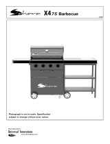
3-BURNER
LP GAS GRILL
Model #DGC310CNP/DGC310CNP-D
#DGC310RNP/DGC310RNP-D
#DGC310BNP/DGC310BNP-D
#DGC310GNP/DGC310GNP-D
ATTACH YOUR RECEIPT HERE
Serial Number _____________________________ Purchase Date ______________________
Questions, problems, missing parts? Before returning to your retailer, call our customer
service department at 1-877-447-4768, 8:30 a.m. – 4:30 p.m., CST, Monday – Friday
or e-mail us at [email protected].
Français p.
XX
Español p.
XX
Français p. 28
Español p. 55

2
Assembler/Installer: This manual contains important information necessary for the proper
assembly and safe use of this appliance. Read and follow all warnings and instructions before
assembling and using this appliance. Leave these instructions with the consumer.
Consumer/User: Follow all warnings and instructions when using this appliance.
Retain these instructions for future reference.
TABLE OF CONTENTS
Safety Information ...................................................................................................................... 3
Package Contents ...................................................................................................................... 5
Hardware Contents .................................................................................................................... 6
Preparation ................................................................................................................................. 6
Assembly Instructions ................................................................................................................ 7
Operation Instructions ................................................................................................................. 15
Care and Maintenance ................................................................................................................. 20
Troubleshooting ........................................................................................................................... 23
Warranty ...................................................................................................................................... 25
Replacement Parts List .............................................................................................................. 26
If you smell gas:
1. Shut off gas to the appliance.
2. Extinguish any open ame.
3. Open lid.
4. If odor continues, keep away
from the appliance and immedi-
ately call your local re depart-
ment.
1. Do not store or use gasoline
or other ammable liquids or
vapors in the vicinity of this or
any other appliance.
2. An LP (liquid propane) cylin-
der not connected for use shall
not be stored in the vicinity of
this or any other appliance.
3. This grill is for outdoor use
only and shall not be used in a
building, garage, under over-
hangs or any other enclosed
area.
4. Do not leave a lit grill unat-
tended. Keep children and pets
away from the grill at all times.
WARNING
DANGER

3
DANGER
CAUTION
• Do not use in an explosive atmosphere. Keep grill area clear and free from combustible
materials, gasoline and other ammable vapors and liquids.
Please read and understand this entire manual before attempting to assemble, operate or install
the product. If you have any questions regarding the product, please call customer service at:
1-877-447-4768, 8:30 a.m. – 4:30 p.m., CST, Monday – Friday.
• Never use charcoal or lighter uid with the grill.
• Do not use gasoline, kerosene or alcohol for lighting.
• The LP gas cylinder used with this appliance must be:
(a) Constructed and marked in accordance with the Specications for LP-Gas Cylinders
of the U.S. Department of Transportation (D.O.T.) or the National Standard of Canada,
CAN/CSA-B339, Cylinders, Spheres and Tubes for Transportation of Dangerous Goods;
and Commision, as applicable; and
(b) Provided with a listed overlling prevention device.
(c) Provided with a cylinder connection device compatible with the connector for outdoor
cooking appliances. This grill is not intended to be used in or installed on recreational
vehicles and/or boats.
• Never keep a lled container in a hot car or car trunk. Heat will cause the gas pressure to
increase, which may open the relief valve and allow gas to escape.
• Always open grill lid slowly and carefully as heat and steam trapped within the grill can burn
you severely.
SAFETY INFORMATION

4
SAFETY INFORMATION
• Do not place the grill under overhead
combustible construction or awnings.
Minimum clearance from sides and
back of unit to combustible construction,
36 inches (914.4mm) from sides and
back.
NOTE: The installation must conform with
local codes or, in the absence of local
codes, with either the National Fuel Gas
Code, ANSI Z223.1/NFPA 54, Natural
Gas and Propane Installation Code, CSA
B149.1, or Propane Storage and
Handling Code, B149.2.
CAUTION
• Do not store or use gasoline or other ammable liquids or vapors in the vicinity of this or any
other appliance.
• An LP cylinder not connected for use shall not be stored in the vicinity of this or any other
appliance.
• This grill is for use with propane gas only (propane cylinder not included).
• Never attempt to attach this grill to the self-contained propane system of a boat, camper trailer,
motor home or house.
• Do not attempt to move the grill while it is lit or when it is hot. The casters should be locked
when not moving the grill.
• Do not use the grill unless it is completely assembled and all parts are securely fastened and
tightened.
• Keep all combustible items and surfaces at least 36 inches (91.44 cm) away from the grill at all
times.
• Do not touch metal parts of grill until it has completely cooled (about 45 minutes) to avoid
burns, unless you are wearing protective gear (pot holders, gloves, BBQ mittens, etc…).
• Do not alter this grill in any manner.
• Clean and inspect the hose before each use. If there is evidence of abrasion, wear, cuts, or
leaks, the hose must be replaced prior to operating the appliance. The replacement hose
assembly will be that which is specied by the manufacturer.
• Move gas hoses as far away as possible from hot surfaces and dripping hot grease.
• Keep the grill’s valve compartment, burners and circulating air passages clean. Inspect the
grill before each use. Do not obstruct the ow of gas or ventilation air.
• The use of alcohol, prescription or non-prescription drugs may impair the operator’s ability
to properly assemble or safely operate the grill.
• Do not leave a lit grill unattended. Keep children and pets away from the grill at all times.
• Do not place this grill on any type of tabletop surface. The grill should be placed on a at and
level surface.
• Do not use the grill in high winds.
WARNING

5
PACKAGE CONTENTS
PART DESCRIPTION QUANTITY
A Warming Rack 1
B Hood and Grill Body Assembly 1
C Cooking Grate 1
D Heat Tent 3
E LP Gas Tank Heat Shield 1
F Side Table Assembly 2
G Grease Cup 1
H Cart Rear Upper Brace Assembly 1
I Cart Rear Lower Brace Assembly 1
J Left Rear Leg Assembly 1
K Cart Left Upper Brace Assembly 1
L Left Front Leg Assembly 1
PART DESCRIPTION QUANTITY
M Cart Left Lower Brace Assembly 1
N Right Rear Leg Assembly 1
O Right Front Leg Assembly 1
P Tank Retention Bracket 1
Q Tank Retention Support Bracket 1
R Cart Front Panel 1
S Cart Right Upper Brace Assembly 1
T Left Rear Leg Cap 1
U
Left Front Leg Cap
1
V
Wheel
2
W Tank Support Bracket 1
X Cylinder Block Bar 1
B
C
D
A
H
G
E
F
F
I
X
K
L
N
O
M
P
Q
R
W
T
S
U
V
J

6
HARDWARE CONTENTS
M6x12
Bolt
Qty. 30
M6
Wingnut
Qty. 1
M6x18
Bolt
Qty. 2
M5
Wingnut
Qty. 1
Wheel axle
Qty. 2
Cotter pin
Qty. 2
M4x12
Bolt
Qty. 6
M6x26
Bolt
Qty. 1
PREPARATION
Before beginning assembly of product, make sure all parts are present. Compare parts with package
contents list on previous page and hardware contents above. If any part is missing or damaged, do
not attempt to assemble the product. Contact customer service for replacement parts.
Estimated Assembly Time: 50 minutes with 2 people
Tools Required for Assembly and Leak Testing (not included): Phillips screwdriver, Spray bottle,
Plier, Adjustable wrench
CAUTION
THIS UNIT IS HEAVY. Two people required for safe assembly.
Two people required for safe assembly. Some parts may contain sharp edges. Wear protective
gloves if necessary. Read and follow all safety statements, warnings, assembly instructions and
use and care instructions before attempting to assemble and use.
CC
AA
BB
DD
GG
EE
HHFF

7
ASSEMBLY INSTRUCTIONS
1. Install left rear leg cap (T) onto left
rear cart leg (J). Then install left front
leg cap (U) onto left front cart leg(L) as
illustrated. Use four M6x12 bolts (AA) to
fasten the Cart Left Upper Brace Assembly (K)
and Cart Left Lower Brace Assembly (M)
onto Left Front Leg Assembly (L) and Left Rear
Leg Assembly (J).
DO NOT TIGHTEN BOLTS AT THIS TIME.
Hardware Used
M6x12 Bolt
M6x12 Bolt
Cotter Pin
Wheel Axle
x 4
x 4
x 2
x 2
2. Place the tank support bracket (W)
between the Right Front Leg Assembly (O) and
Right Rear Leg Assembly (N), use two
wheel axles (BB) to go through the both two
wheels (V), right front leg assembly (O)
and right rear leg assembly (N), then insert
the two cotter pins (CC) to secure. Use
four M6x12 bolts (AA) to fasten the Cart
Right Upper Brace Assembly (S) onto the right
front leg assembly (O) and right rear leg
assembly (N).
Note: Follow the arrow direction on the Cart
Right Upper Brace Assembly (S) when install.
DO NOT TIGHTEN BOLTS AT THIS TIME.
Hardware Used
2
AA
AA
BB
CC
1
M
J
T
U
L
K
AA
N
V
W
O
AA
BB
S
CC

8
ASSEMBLY INSTRUCTIONS
3. Use four M4x12 bolts (DD) to assemble the
cart front panel (R) between the Right Front
Leg Assembly (O) and Left Front Leg
Assembly (L).
Note: The small edge of the front panel (R)
should be on top.
DO NOT TIGHTEN BOLTS AT THIS TIME.
Hardware Used
DD
AA
H
M4x12 Bolt
x 4
4. Use four M6x12 bolts (AA) Fasten the Cart
Rear Upper Brace Assembly (H) onto Left
Rear Leg Assembly (J) and Right Rear Leg
Assembly (N).
Note: Follow the arrow direction on the Cart
Rear Upper Brace Assembly (H)
when installing.
DO NOT TIGHTEN BOLTS AT THIS TIME.
3
4
R
O
N J
L
Hardware Used
AA
M6x12 Bolt
x 4
DD

9
AA
HH
M6x12 Bolt
x 4
x 1
ASSEMBLY INSTRUCTIONS
5. Use one M6X26 bolts (EE) and one M6 wing
nut (FF) to assemble the Tank Retention Bracket
(P) to Tank Retention support Bracket (Q).
Fasten Tank Retention Bracket (P) and Tank
Retention support Bracket assembly (P+Q) in
the Cart Right Upper Brace Assembly (S)
by using two M6x18 bolts (GG).
6. Insert one of the end of cylinder block bar (X)
into the hole on the bottom of front
panel, insert the other end with thread onto
the Cart Rear Lower Brace Assembly (I). Use
one M5 wingnut (HH) to fasten the cylinder
block bar (X) onto the Cart Rear Lower Brace
Assembly (I). Use four M6x12 bolts (AA) to
fasten the Cart Rear Lower Brace Assembly(I)
onto the two rear leg assembly.
Note: Follow the arrow direction on the Cart
Right Lower Brace Assembly (I) when install.
DO NOT TIGHTEN BOLTS AT THIS TIME.
5
6
Hardware Used
EE
FF
GG
M6x26 Bolt
M6x18 Bolt
M6 Wingnut
x 1
x 1
x 2
AA
P&Q
X
HH
I
Hardware Used
GG
EE
Q
P
S
FF
M5 Wingnut

10
ASSEMBLY INSTRUCTIONS
8. Use two M4x12 bolts (DD) to fasten the LP gas
tank heat shield (E) on the grill body right
brace.
7. With the help of a friend, place hood and grill
body assembly (B) on cart assembly. Use six
M6x12 bolts (AA) to fasten.
Note: When performing Step7, lift grill body
from front and rear panels to avoid injury to
hands and ngers.
Once hood and grill body assembly (B) is
placed correctly onto cart assembly,
tighten ALL bolts securely from Steps 1, 2,
3, 4, and 6.
7
8
Hardware Used
Hardware Used
B
AA
E
DD
AA
M6x12 Bolt
x 6
DD
M4x12 Bolt
x 2

11
ASSEMBLY INSTRUCTIONS
9. Pre-assemble two M6x12 bolts (AA) onto the
upper of left brace of hood and grill body
assembly (B) and do not tighten them and
make sure to leave a 5mm gap between the
bolt and left brace of hood and grill body.
Hang one of the Side Table Assembly (F)
on the bolts and fasten the Side Table
Assembly (F) with two M6x12 bolts (AA). Then
tighten all the four bolts.
9
10. Pre-assemble two M6x12 bolts (AA) onto
the upper of right brace of hood and grill body
assembly (B) and do not tighten
them and make sure to leave a 5mm gap
between the bolt and right brace of hood
and grill body. Hang one of the Side Table
Assembly (F) on the bolts and
fasten the Side Table Assembly (F) with two
M6x12 bolts (AA). Then tighten all the four
bolts.
10
Hardware Used
Hardware Used
AA
AA
F
F
5mm
AA
AA
M6x12 Bolt
M6x12 Bolt
x 4
x 4
5mm

12
WARNING: IT IS VER Y IMPORT ANT TO CHECK
AND ENSURE THA T EACH AND EVER Y BURNER
IS FULLY ENGAGED WITH THE ADJACENT VALVE
ORIFICE BEFORE COMPLETING STEP 1 1.
FAILURE TO DO SO MAY RESULT IN FIRE OR
EXPLOSION, POSSIBLY CAUSING SERIOUS
INJURY OR DEATH. REFER TO MAINTENANCE
SECTION INSTRUCTIONS TO PROPERLY CHECK
THE ENGAGEMENT.
Wrong
Wrong
Correct
ASSEMBLY INSTRUCTIONS
11. Put the three heat tents(D) into place over
each burner.
11
D
C
12. Put one cooking grate(C) in place.
12
WARNING: IT IS VERY IMPORTANT TO CHECK
AND ENSURE THAT EACH AND EVERY BURNER
IS FULLY ENGAGED WITH THE ADJACENT VALVE
ORIFICE BEFORE COMPLETING STEP 11.
FAILURE TO DO SO MAY RESULT IN FIRE OR
EXPLOSION, POSSIBLY CAUSING SERIOUS
INJURY OR DEATH. REFER TO MAINTENANCE
SECTION INSTRUCTIONS TO PROPERLY CHECK
THE ENGAGEMENT.

13
13
ASSEMBLY INSTRUCTIONS
13. Put one warming rack (A) in place.
A
14. Slide grease cup (G) onto tracks in the bottom
of rebox as illustrated.
14
G
G

14
15
ASSEMBLY INSTRUCTIONS
15. Place gas cylinder (sold separately) upright
into the notches of the tank support bracket on
the bottom of right legs, orient the cylinder
such that the valve opening faces the right
side of the grill, and the hose is not kinked or
damaged. Loose and slide down tank retention
bracket over LP Gas cylinder collar ,then use
the wing nut to secure tightly. Hand-tighten the
hose/regulator coupling to the threaded valve
of the LP gas cylinder.
Tank support bracket
Front
Back
Tank retention bracket

15
OPERATION INSTRUCTIONS
CHECKING FOR LEAKS
After all connections are made, check all connections and ttings on the LP gas tank valve, gas hose
and regulator for leaks with a water and soap solution.
To prevent re or explosion while testing for a leak:
• Always perform leak test prior to lighting the grill.
• Do not smoke while testing for a leak.
• Always perform leak tests outdoors in a well-ventilated area.
• Do not use any source of ame while testing for leaks.
• Do not use the grill until any and all leaks are corrected.
• If you are unable to correct a leak, disconnect the propane supply and call a gas appliance service
dealer.
PERFORM LEAK TEST
• Prepare leak test solution by 50/50 ratio of liquid dish soap and water.
Total solution required is approximately 2 - 3 ounces (70 - 90 ml).
Put leak test solution in a spray bottle.
• Ensure all control knobs are in the O OFF position.
• Connect the gas hose to the gas supply.
• Open the LP gas tank valve.
• Spray leak test solution on all gas carrying connections and ttings. Presence of bubbles at areas
of applied test solution indicates a gas leak. If leaks are detected or you smell or hear gas, shut off the
gas supply valve immediately and repair or replace the defective part. Do not use the grill until
all leaks are corrected.
WARNING
ALL INSTRUCTIONS AND SAFEGUARDS ON THIS PAGE MUST BE FOLLOWED TO
PREVENT FIRE, DAMAGE AND/OR INJURY.
CAUTION
Only use the regulator and hose assembly provided! If a replacement is necessary, please call
our customer service center. Do not use replacement parts that are not intended for this grill.

26
REPLACEMENT PARTS LIST
3
6
4
16
9
2
32
22
21
14
12
5
17
15
10
33
31
34
23
23
20
11
13
8
25
28
30
26
27
24
37
36
35
29
18
19
1
41
42
40
39
38
7

27
REPLACEMENT PARTS LIST
For replacement parts, call our customer service department at 1-877-447-4768, 8:30 a.m. – 4:30 p.m.,
CST, Monday – Friday.
70-10-661
Printed in China
PART DESCRIPTION PART#
1 Hood Black 70-01-663 / Blue 70-01-757 / Red 70-01-758 / Green 70-01-759
2 Badge 70-10-540
3 Lid Handle Heat Shield Assembly 70-01-664
4 Lid Bumper 70-01-665
5 Warming Rack 70-01-666
6 Hood Handle 70-01-667
7 Lid Hinge 70-01-668
8 Grill Body Hinge 70-01-669
9 Cooking Grate 70-01-670
10 Lid Axle with cotter pin 70-01-671
11 Heat Tent Bracket 70-01-672
12 Heat Tent 70-01-673
13 Grill Body 70-01-674
14 Grease Cup 70-01-675
15 Main Burner with cotter pin 70-01-676
16 Control Panel Assembly US only 70-01-677
17 Main Valves And Manifold Assembly 70-01-679
18 Match Holder with Chain 70-01-204
19 Main Burner Sparker 70-01-680
20 Control Knob 70-01-681
21 Regulator and Hose Assembly 70-01-647
22 Grill Body Support Assembly 70-01-682
23 Side Table Assembly 70-01-683
24 LP Gas tank Heat Shield 70-01-684
25 Left Rear Leg Assembly 70-01-685
26 Cart Left Upper Brace Assembly 70-01-686
27 Cart Rear Upper Brace Assembly 70-01-687
28 Cart Rear Lower Brace Assembly 70-01-688
29 Tank Retention Bracket 70-01-689
30 Right Rear Leg Assembly 70-01-690
31 Tank Retention Support Bracket 70-01-691
32 Cart Right Upper Brace Assembly 70-01-692
33 Cart Front Panel Black 70-01-693 / Blue 70-01-760 / Red 70-01-761 / Green 70-01-762
34 Left Rear Leg Cap 70-01-694
35 Cart Left Lower Brace Assembly 70-01-695
36 Left Front Leg Assembly 70-01-696
37 Left Front Leg Cap 70-01-697
38 Right Front Leg Assembly 70-01-698
39 Tank Support Bracket 70-01-699
40 Wheel 70-01-700
41 Cylinder Block Bar 70-01-701
42 Wheel axle 70-01-702
n/a Instruction manual 70-10-661
n/a Hardware pack 70-09-522
/