
Operating Instructions and Parts Manual
10-inch Contractor Table Saw
Model 64B
Powermatic
427 New Sanford Road
LaVergne, Tennessee 37086 Part No. M-1791229
Ph.: 800-274-6848 Revision B2 10/2018
www.powermatic.com Copyright © 2018 Powermatic
This .pdf document is bookmarked

2
1.0 Warranty and Service
Powermatic
®
warrants every product it sells against manufacturers’ defects. If one of our tools needs service or
repair, please contact Technical Service by calling 1-800-274-6846, 8AM to 5PM CST, Monday through Friday.
Warranty Period
The general warranty lasts for the time period specified in the literature included with your product or on the official
Powermatic branded website.
Powermatic products carry a limited warranty which varies in duration based upon the product. (See chart
below)
Accessories carry a limited warranty of one year from the date of receipt.
Consumable items are defined as expendable parts or accessories expected to become inoperable within a
reasonable amount of use and are covered by a 90 day limited warranty against manufacturer’s defects.
Who is Covered
This warranty covers only the initial purchaser of the product from the date of delivery.
What is Covered
This warranty covers any defects in workmanship or materials subject to the limitations stated below. This warranty
does not cover failures due directly or indirectly to misuse, abuse, negligence or accidents, normal wear-and-tear,
improper repair, alterations or lack of maintenance. Powermatic woodworking machinery is designed to be used with
Wood. Use of these machines in the processing of metal, plastics, or other materials outside recommended
guidelines may void the warranty. The exceptions are acrylics and other natural items that are made specifically for
wood turning.
Warranty Limitations
Woodworking products with a Five Year Warranty that are used for commercial or industrial purposes default to a
Two Year Warranty. Please contact Technical Service at 1-800-274-6846 for further clarification.
How to Get Technical Support
Please contact Technical Service by calling 1-800-274-6846. Please note that you will be asked to provide proof
of initial purchase when calling. If a product requires further inspection, the Technical Service representative will
explain and assist with any additional action needed. Powermatic has Authorized Service Centers located throughout
the United States. For the name of an Authorized Service Center in your area call 1-800-274-6846 or use the Service
Center Locator on the Powermatic website.
More Information
Powermatic is constantly adding new products. For complete, up-to-date product information, check with your local
distributor or visit the Powermatic website.
How State Law Applies
This warranty gives you specific legal rights, subject to applicable state law.
Limitations on This Warranty
POWERMATIC LIMITS ALL IMPLIED WARRANTIES TO THE PERIOD OF THE LIMITED WARRANTY FOR EACH
PRODUCT. EXCEPT AS STATED HEREIN, ANY IMPLIED WARRANTIES OF MERCHANTABILITY AND FITNESS
FOR A PARTICULAR PURPOSE ARE EXCLUDED. SOME STATES DO NOT ALLOW LIMITATIONS ON HOW
LONG AN IMPLIED WARRANTY LASTS, SO THE ABOVE LIMITATION MAY NOT APPLY TO YOU.
POWERMATIC SHALL IN NO EVENT BE LIABLE FOR DEATH, INJURIES TO PERSONS OR PROPERTY, OR
FOR INCIDENTAL, CONTINGENT, SPECIAL, OR CONSEQUENTIAL DAMAGES ARISING FROM THE USE OF
OUR PRODUCTS. SOME STATES DO NOT ALLOW THE EXCLUSION OR LIMITATION OF INCIDENTAL OR
CONSEQUENTIAL DAMAGES, SO THE ABOVE LIMITATION OR EXCLUSION MAY NOT APPLY TO YOU.
Powermatic sells through distributors only. The specifications listed in Powermatic printed materials and on the official
Powermatic website are given as general information and are not binding. Powermatic reserves the right to effect at
any time, without prior notice, those alterations to parts, fittings, and accessory equipment which they may deem
necessary for any reason whatsoever.
Product Listing with Warranty Period
90 Days – Parts; Consumable items
1 Year – Motors, Machine Accessories
2 Year – Woodworking Machinery used for industrial or commercial purposes
5 Year – Woodworking Machinery
NOTE: Powermatic is a division of JPW Industries, Inc. References in this document to Powermatic also apply to
JPW Industries, Inc., or any of its successors in interest to the Powermatic brand.

3
2.0 Table of contents
Section Page
1.0 Warranty and Service ..................................................................................................................................... 2
2.0 Table of contents ............................................................................................................................................ 3
3.0 Safety warnings .............................................................................................................................................. 4
3.1 Kickback ..................................................................................................................................................... 5
4.0 About this manual .......................................................................................................................................... 6
5.0 Glossary ......................................................................................................................................................... 7
6.0 Features ......................................................................................................................................................... 8
7.0 Specifications ................................................................................................................................................. 8
8.0 Setup and Assembly .................................................................................................................................... 10
8.1 Shipping contents ..................................................................................................................................... 10
8.2 Unpacking and cleanup ............................................................................................................................ 11
8.3 Stand assembly ........................................................................................................................................ 12
8.4 Mounting saw to stand ............................................................................................................................. 13
8.5 Installing handwheels/hooks .................................................................................................................... 13
8.6 Installing table extensions ........................................................................................................................ 14
8.7 Leveling table extensions ......................................................................................................................... 14
8.8 Rails and Fence ....................................................................................................................................... 14
8.9 Wood Extension Table ............................................................................................................................. 14
8.10 Switch bracket ........................................................................................................................................ 15
8.11 Motor cover ............................................................................................................................................ 15
8.12 Table insert ............................................................................................................................................. 15
8.13 Installing and removing blade ................................................................................................................. 15
8.14 Riving knife ............................................................................................................................................. 16
8.15 Blade guard ............................................................................................................................................ 16
9.0 Electrical connections .................................................................................................................................. 16
9.1 Grounding instructions ............................................................................................................................. 16
9.2 Voltage conversion ................................................................................................................................... 17
9.3 Extension cords ........................................................................................................................................ 17
9.4 Switch lockout .......................................................................................................................................... 18
10.0 Adjustments ............................................................................................................................................... 18
10.1 Fence alignment ..................................................................................................................................... 18
10.2 Blade raising/tilt mechanism ................................................................................................................... 18
10.3 Miter gauge ............................................................................................................................................ 18
10.4 Positive blade stops ............................................................................................................................... 19
10.5 Riving knife alignment ............................................................................................................................ 20
10.6 Low profile riving knife ............................................................................................................................ 20
10.7 Trunnion adjustment ............................................................................................................................... 20
10.8 Table to blade alignment ........................................................................................................................ 20
10.9 Belt tension and replacement ................................................................................................................. 21
11.0 Operations .................................................................................................................................................. 21
12.0 Safety devices ............................................................................................................................................ 26
13.0 Maintenance ............................................................................................................................................... 27
14.0 Optional accessories .................................................................................................................................. 28
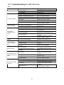
15.0 Troubleshooting the 64B Table Saw .......................................................................................................... 29
16.0 Replacement Parts ..................................................................................................................................... 30
16.1.1 Table and Cabinet Assembly – Exploded View ................................................................................... 30
16.1.2 Table and Cabinet Assembly – Parts List ........................................................................................... 31
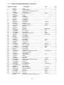
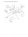
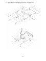
16.2.1 Motor and Trunnion Assembly – Exploded View ................................................................................. 32
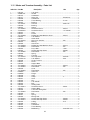
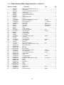
16.2.2 Motor and Trunnion Assembly – Parts List ......................................................................................... 33
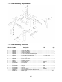
16.3.1 Stand Assembly – Exploded View ....................................................................................................... 35
16.3.2 Stand Assembly – Parts List ............................................................................................................... 35
16.4.1 Blade Guard and Miter Gauge Assemblies – Exploded View ............................................................. 36
16.4.2 Blade Guard and Miter Gauge Assemblies – Parts List ...................................................................... 37
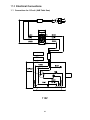
17.0 Electrical Connections ................................................................................................................................ 38
17.1 Connections for 115 volt (64B Table Saw) ............................................................................................ 38
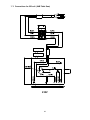
17.2 Connections for 230 volt (64B Table Saw) ............................................................................................ 39

3.0 Safety warnings
1. Read and understand the entire owner's
manual before attempting assembly or
operation.
2. Read and understand the warnings posted on
the machine and in this manual. Failure to
comply with all of these warnings may cause
serious injury.
3. Replace the warning labels if they become
obscured or removed.
4. This table saw is designed and intended for
use by properly trained and experienced
personnel only. If you are not familiar with the
proper and safe operation of a table saw, do
not use until proper training and knowledge
have been obtained.
5. Do not use this table saw for other than its
intended use. If used for other purposes,
Powermatic disclaims any real or implied
warranty and holds itself harmless from any
injury that may result from that use.
6. Always wear approved safety glasses/face
shields while using this table saw. Everyday
eyeglasses only have impact resistant lenses;
they are not safety glasses.
7. Before operating this table saw, remove tie,
rings, watches and other jewelry, and roll
sleeves up past the elbows. Remove all loose
clothing and confine long hair. Non-slip
footwear or anti-skid floor strips are
recommended. Do not wear gloves.
8. Always use the blade guard on all ''through-
sawing'' operations. A through-sawing
operation is one in which the blade cuts
completely through the workpiece.
9. Kickback occurs when the workpiece is thrown
towards the operator at a high rate of speed. If
you do not have a clear understanding of
kickback and how it occurs, DO NOT operate
this table saw!
10. Wear ear protectors (plugs or muffs) during
extended periods of operation.
11. Do not operate this machine while tired or
under the influence of drugs, alcohol or any
medication.
12. Make certain switch is in the OFF position
before connecting machine to power supply.
13. Make certain the machine is properly
grounded.
14. Make all machine adjustments or maintenance
with the machine unplugged from the power
source.
15. Remove adjusting keys and wrenches. Form a
habit of checking to see that keys and
adjusting wrenches are removed from the
machine before turning it on.
16. Keep safety guards in place at all times when
the machine is in use. If removed for
maintenance purposes, use extreme caution
and replace the guards immediately after
completion of maintenance.
17. Check damaged parts. Before further use of
the machine, a guard or other part that is
damaged should be carefully checked to
determine that it will operate properly and
perform its intended function. Check for
alignment of moving parts, binding of moving
parts, breakage of parts, mounting and any
other conditions that may affect its operation.
A guard or other part that is damaged should
be properly repaired or replaced.
18. Provide for adequate space surrounding work
area and non-glare, overhead lighting.
19. Keep the floor around the machine clean and
free of scrap material, oil and grease.
20. Keep visitors a safe distance from the work
area. Keep children away.
21. Make your workshop child proof with padlocks,
master switches or by removing starter keys.
22. Give your work undivided attention. Looking
around, carrying on a conversation and “horse-
play” are careless acts that can result in
serious injury.
23. Maintain a balanced stance at all times so that
you do not fall into the blade or other moving
parts. Do not overreach or use excessive force
to perform any machine operation.
24. Use the right tool at the correct speed and
feed rate. Do not force a tool or attachment to
do a job for which it was not designed. The
right tool will do the job better and more safely.
25. Use recommended accessories; improper
accessories may be hazardous.
26. Maintain tools with care. Keep saw blades
sharp and clean for the best and safest
performance. Follow instructions for lubricating
and changing accessories.
27. Turn off the machine before cleaning. Use a
brush or compressed air to remove chips or
debris — do not use your hands.
28. Do not stand on the machine. Serious injury
could occur if the machine tips over.

5
29. Never leave the machine running unattended.
Turn the power off and do not leave the
machine until it comes to a complete stop.
30. Remove loose items and unnecessary work
pieces from the area before starting the
machine.
31. Keep hands out of the line of saw blade.
32. Use a push-stick when required.
33. Pay particular attention to instructions on
reducing risk of kickback.
34. Do not perform any operation freehand.
35. Never reach around or over saw blade.
36. Don’t use in dangerous environment. Don’t
use power tools in damp or wet location, or
expose them to rain. Keep work area well
lighted.
3.1 Kickback
The most common accidents among table saw
users, according to statistics, can be linked to
kickback, the high-speed expulsion of material from
the table that can strike the operator. Kickback can
also result in the operator’s hands being pulled into
the blade.
Kickback Prevention
Tips to avoid the most common causes of
kickback:
Make sure the riving knife is always aligned
with the blade. A workpiece can bind or stop
the flow of the cut if the riving knife is
misaligned, and result in kickback.
Use a riving knife during every cut. The riving
knife maintains the kerf in the workpiece,
which will reduce the chance of kickback.
Never attempt freehand cuts. The workpiece
must be fed parallel to the blade, otherwise
kickback will likely occur. Always use the rip
fence or miter gauge to support the workpiece.
Make sure that rip fence is parallel to blade. If
not, the chances of kickback are very high.
Take the time to check and adjust the rip
fence.
Feed cuts through to completion. Anytime you
stop feeding a workpiece that is in the middle
of a cut, the chance of binding, resulting in
kickback, is greatly increased.
Protection Tips from Kickback
Kickback can happen even if precautions are taken
to prevent it. Listed below are some tips to protect
you if kickback does occur:
Stand to the side of the blade when cutting. An
ejected workpiece usually travels directly in
front of the blade.
Wear safety glasses or a face shield. Your
eyes and face are the most vulnerable part of
your body.
Never place your hand behind the blade. If
kickback occurs, your hand will be pulled into
the blade.
Use a push stick to keep your hands farther
away from the moving blade. If a kickback
occurs, the push stick will most likely take the
damage that your hand would have received.
WARNING: Drilling, sawing, sanding or
machining wood products generates wood dust
and other substances known to the State of
California to cause cancer. Avoid inhaling dust
generated from wood products or use a dust
mask or other safeguards for personal
protection.
Wood products emit chemicals known to the
State of California to cause birth defects or other
reproductive harm. For more information go to
http://www.p65warnings.ca.gov/wood.
WARNING: This product can expose you to
chemicals including cadmium, which is known to
the State of California to cause cancer and birth
defects or other reproductive harm. For more
information go to http://www.p65warnings.ca.
gov.

6
Familiarize yourself with the following safety notices used in this manual:
This means that if precautions are not heeded, it may result in minor injury and/or possible
machine damage.
This means that if precautions are not heeded, it may result in serious injury or possibly even
death.
4.0 About this manual
This manual is provided by Powermatic covering the safe operation and maintenance procedures for a
Powermatic Model 64B Contractor Table Saw. This manual contains instructions on installation, safety
precautions, general operating procedures, maintenance instructions and parts breakdown. Your machine has
been designed and constructed to provide consistent, long-term operation if used in accordance with the
instructions as set forth in this document.
This manual is not intended to be an exhaustive guide to table saw operational methods, use of jigs or after-
market accessories, choice of stock, etc. Additional knowledge can be obtained from experienced users or
trade articles. Whatever accepted methods are used, always make personal safety a priority.
If there are questions or comments, please contact your local supplier or Powermatic. Powermatic can also be
reached at our web site: www.powermatic.com.
Retain this manual for future reference. If the machine transfers ownership, the manual should accompany it.
Read and understand the entire contents of this manual before attempting assembly
or operation. Failure to comply may cause serious injury.

7
5.0 Glossary
Arbor: Metal shaft that connects the drive
mechanism to the blade.
Bevel Edge Cut: Tilt of the saw arbor and blade
between 0° and 45° to perform an angled cutting
operation.
Blade Guard: Mechanism mounted over the saw
blade to prevent accidental contact with the cutting
edge.
Crosscut: Sawing operation in which the miter
gauge is used to cut across the grain of the
workpiece.
Dado Blade: Blade used for cutting grooves and
rabbets. A stacked dado set can be used for wider
grooves.
Dado Cut: Flat bottomed groove in the face of the
workpiece made with a dado blade.
Featherboard: Device used to keep a board
against the rip fence or table that allows the
operator to keep hands away from saw blade.
Freehand: Moving a workpiece into the blade
using only the hands, without a fixed positioning
device. (This is a dangerous, unacceptable
procedure – always use appropriate devices to
feed the workpiece though the saw blade during
cutting operations.)
Kerf: The resulting cut or gap made by a saw
blade.
Kerf, Standard: 1/8" gap made with a standard
blade.
Kickback: An event in which the workpiece is lifted
up and thrown back toward the operator, caused
when a workpiece binds on the saw blade or
between the blade and rip fence (or other fixed
object). To minimize or prevent injury from
kickbacks, see the Operations section.
Miter Gauge: A component that controls the
workpiece movement while performing a crosscut
of various angles.
Non-Through Cut: A sawing operation that
requires the removal of the blade guard and
standard riving knife, resulting in a cut that does
not protrude through the top of the workpiece
(includes Dado and rabbet cuts).
The blade guard and riving knife must be re-
installed after performing a non-through cut to
avoid accidental contact with the saw blade during
operation.
Parallel: Two lines or surfaces lying at equal
distance from each other at every point along their
lengths. For example, a rip fence must be parallel
to the side face of the saw blade.
Pawls, Anti-Kickback: Plates with a serrated
edge, usually mounted to the splitter, that prevent
the cut workpiece being drawn back toward the
blade and producing kickback.
Perpendicular: 90° (right angle) intersection or
position of the vertical and horizontal planes such
as the position of the saw blade (vertical) to the
table surface (horizontal).
Push Board/Push Stick: An instrument used to
safely push the workpiece through the cutting
operation.
Rabbet: A cutting operation that creates an
L-shaped channel along the edge of the board.
Resaw: Process of cutting a thick workpiece into
thinner pieces.
Rip Cut: A cut made along the grain of the
workpiece.
Riving Knife: A metal plate fixed relative to the
blade, which moves with the blade as cutting depth
is adjusted. Thus, it maintains not only the kerf
opening in the workpiece, but also the knife-to-
blade distance. A low-profile riving knife sits lower
than the top edge of the blade, and is used for non-
through cuts.
Splitter (Spreader): A stationary metal plate to
which the blade guard is attached that maintains
the kerf opening in the workpiece when performing
a cutting operation. A splitter that rises and lowers
with the blade is called a riving knife.
Straightedge: A tool used to check that a surface
is flat or parallel.
Through Sawing: A sawing operation in which the
workpiece thickness is completely sawn through.
Proper blade height usually allows 1/8" of the top
of blade to extend above the wood stock. Keep the
blade guard down, the anti-kickback pawls down,
and the riving knife in place over the blade.

8
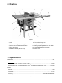
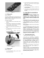
6.0 Features
Figure 1
1 – Cast iron table extensions
2 – T-slots
3 – Transparent blade guard with riving knife
4 – Precision miter gauge with extension face
5 – Accu-Fence
®
6 – Rail set (30” shown)
7 – Blade tilt handwheel (with lock knob)
8 – Blade tilt angle scale
9 – Accu-Fence storage hook
10 – Adjustable foot pads
11 – Blade elevation handwheel (with lock knob)
12 – Miter gauge storage hook
13 – Industrial style push button switch
14 – Motor cover
7.0 Specifications
Model number ........................................................................................................................................................... 64B
Stock Numbers:
Model 64B basic saw – with stand, no fence or rails ..................................................................................... 1791229
Model 64B basic saw – with 30” Rail Set, Accu-Fence
®
, 27”x17” Wood Extension Table ..........................1791229K
Model 64B basic saw – with 50” Rail Set, Accu-Fence
®
, 27”x36” Wood Extension Table, Legs .................1791230K
Materials:
Stand .................................................................................................................................................................... steel
Saw body .............................................................................................................................................................. steel
Tables ................................................................................................................................................. ground cast iron
Handwheels .................................................................................................................................................... cast iron
Trunnion ......................................................................................................................................................... cast iron
Fence body ....................................................................................................................... steel with HDPE side plates

9
Motor and Electricals:
Motor type.................................................................................. totally enclosed fan cooled, induction, capacitor start
Horsepower ..................................................................................................................................... 1-3/4 HP (1.3 kW)
Phase ................................................................................................................................................................. single
Voltage ............................................................................................................................... 115/230V (prewired 115V)
Cycle .................................................................................................................................................................. 60 Hz
Motor speed................................................................................................................................................. 3450 RPM
Listed FLA (full load amps) ..............................................................................................................................15/7.5 A
Starting amps ........................................................................................................................................................ 52A
Running amps (no load) .......................................................................................................................................... 6A
Start capacitor .................................................................................................................................. 400MFD 125VAC
Run capacitor ............................................................................................................................................. 30F 250V
Power transfer ..................................................................................................................................................... v-belt
On/off switch ................................................................................................ manual industrial-style, with padlock hole
Power cord length ..................................................................................................................................... 7 ft. (213cm)
Power plug installed ............................................................................................................................................... yes
Recommended circuit size
1
...................................................................................... 30A (for 115V) or 20A (for 230V)
Noise emission:
Without load ............................................................................................................. 78 dB at 20 inches from blade
With load.................................................................................................................. 85 dB at 20 inches from blade
Arbor and blade:
Blade Diameter
2
(in.) ............................................................................................................................... 10” (254mm)
Arbor Diameter (in.) .................................................................................................................................. 5/8” (16mm)
Arbor speed ................................................................................................................................................. 3800 RPM
Arbor lock ............................................................................................................................................................... yes
Maximum cut depth at 90 degrees ........................................................................................................ 3-1/8” (79mm)
Maximum cut depth at 45 degrees ........................................................................................................ 2-1/8” (54mm)
Maximum rip to right of blade ....................................................................................... 30” (762mm) or 50” (1270mm)
Maximum rip to left of blade..................................................................................................................... 12” (305mm)
Dado maximum width .......................................................................................................................... 13/16” (20.7mm
Dado maximum diameter .......................................................................................................................... 8” (200mm)
Blade height per one revolution of handwheel ............................................. 5/32” (4mm) for 90°; 1/8” (2.9mm) for 45°
Blade tilt ..................................................................................................................................................... left, 0 to 45°
Table:
Table working surface ............................................................................................. 20-1/8” L x 27” W (511 x 686mm)
Table working surface, with extensions ................................................................. 44-1/4” L x 27” W (1124 x 686mm)
Table working surface, with extensions and optional wood table:
With 30” rip capacity ......................................................................................... 71-1/4” L x 27” W (1810 x 686mm)
With 50” rip capacity ............................................................................................... 80” L x 27” W (2022 x 686mm)
Table area in front of blade at maximum height................................................................................. 11-1/2” (292mm)
Table height from floor ............................................................................................................................. 36” (914mm)
Miter slot ...................................................................................................... two T-slots, 3/4" W x 3/8” D (19 x 10mm)
Edge bevel............................................................................................................................................................. front
Dust collection:
Dust port outside diameter ........................................................................................................................ 4” (100mm)
Minimum extraction volume required .............................................................................................. 350 cfm (9.9 cmm)
Other:
Stand style ............................................................................................................................................................ open
Stand footprint ............................................................................................................ 21-1/2”L x24”W (546 x 610mm)
Overall Dimensions, shipping carton (basic saw only) ........................... 39” L x 25” W x 22” H (98.6 x 63.6 x 56.4cm)
Overall Dimensions, fully assembled, accessories mounted:
With 30” rip capacity ...................................................................... 71-1/4” L x 43” W x 42” H (181 x 109 x 107cm)
With 50” rip capacity ...................................................................... 79-5/8” L x 43” W x 42” H (202 x 109 x 107cm)
Weights:
Net ........................................................................................................................................................ 293 lb (133 kg)
Shipping ............................................................................................................................................... 304 lb (138 kg)
1
subject to local and national electrical codes.
2
blade not included.
L=length, W=width, H=height

10
8.0 Setup and Assembly
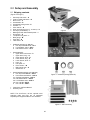
8.1 Shipping contents
(Figures 2 through 7)
1 Saw body with switch – A
2 Cast iron table extensions – B
1 Motor cover – C
2 Handwheels – D
2 Handwheel locking knobs – E
2 Handles – F
1 Arbor wrench – G
2 Open end wrenches (14-17, 10-12mm) – H
4 Hex keys (2.5/3/4/6mm) – I
1 Blade guard with anti-kickback pawls – J
1 Riving knife – K
1 Low profile riving knife – L
1 Miter gauge – M
1 Push stick – N
1 Table insert – O
1 Hardware package (p/n 64B-HP):
6 Hex cap screws M10x30 – HP-1
6 Lock washers 10mm – HP-2
6 Flat washers 10mm – HP-3
1 Stand assembly:
1 Upper brace, with cutout – P
1 Upper brace, long – Q
2 Upper braces, short – R
2 Lower braces, long – S
2 Lower braces, short – T
4 Legs – U
4 Foot pads – V
2 Fence hooks – W
1 Miter gauge hook – X
1 Small hook – Y
1 Stand hardware package (p/n 64B-SHP)
4 Hex cap screws M8x25 – SHP-1
8 Pan head screws M5x15 – SHP-2
24 Carriage bolts M8x16 – SHP-3
40 Flat washers 8mm – SHP-4
28 Lock washers 8mm – SHP-5
36 Hex nuts M8– SHP-6
8 Hex nuts M5 – SHP-7
1 Instructions and Parts Manual
1 Warranty Card
NOTE: The Accu-Fence, rail set, optional wood
extension table and legs, are all packaged
separately and supplied with their own hardware.
Figure 2
Figure 3
Figure 4 – Hardware package (64B-HP)
Figure 5 – Stand assembly

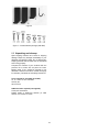
11
Figure 6
Figure 7 – Stand hardware package (64B-SHP)
8.2 Unpacking and cleanup
Open shipping container and check for shipping
damage. Report any damage immediately to your
distributor and shipping agent. Do not discard any
shipping material until the Table Saw is assembled
and running properly.
Compare the contents of your container with the
previous list to make sure all parts are intact.
Missing parts, if any, should be reported to your
distributor. Read the instruction manual thoroughly
for assembly, maintenance and safety instructions.
Tools required for assembly (provided):
10, 12, 14 and 17 mm wrenches
Hex key set
Arbor wrench
Additional tools required (not supplied):
Cross point screwdriver
Rubber mallet or dead-blow hammer (or steel
hammer over a block of wood)

12
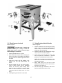
8.3 Stand assembly
Assembly tip: A ratchet wrench with sockets and
extensions will speed assembly time.
1. Assemble stand, using Figure 8 as a guide.
Use the provided carriage bolts, flat washers
lock washers, and hex nuts (SHP-3/4/5/6).
Only make fasteners snug at this time. They
will be fully tightened later, after stand has
settled under the weight of the saw.
2. Note the orientation of the cut-out brace (P) to
the front brace with Powermatic label (R). The
cut-out brace must be to the left, to allow
protrusion of the motor.
3. When stand has been assembled, turn it over
and install the rubber foot pads (V). (Should
you ever need height adjustment on the foot
pad, loosen the two hex nuts, rotate the pad,
then retighten the hex nuts against the metal
of the stand.)
4. Turn stand right-side up. The fasteners are not
fully tight, but they should be snug enough to
withstand the weight of the saw. If the stand
needs more stability, snug fasteners a little
more.
5. The four large holes on top of the stand should
be reasonably aligned through the upper
braces for easy insertion of the screws.
Figure 8

13
Figure 9
8.4 Mounting saw to stand
Refer to Figure 9
The table saw is heavy! Get
persons to assist you in lifting it. Failure to
comply may result in serious personal injury
and/or damage to the machine.
1. Carefully lift table saw out of carton.
2. Place table saw atop the stand, orienting the
motor in the cut-out of the stand, and aligning
the four holes on its bottom edge with those in
the stand.
3. Insert four screws, with flat washers, lock
washers and hex nuts (SHP-1/4/5/6), as
shown.
4. Securely tighten all four hex nuts (SHP-6),
using a 12mm wrench and an additional
wrench to hold the screw steady while
tightening the nut. (NOTE: If you need more
room to wrench the back screws, follow
instructions below for tilting motor out of the
way.)
5. Finish tightening all fasteners in the stand.
8.5 Installing handwheels/hooks
Refer to Figure 9.
1. Install a handwheel onto the tilting and raising
shafts, as shown. Fit the slot of the handwheel
onto the roll pin on the shaft, then secure by
screwing on the locking knob.
2. Install a handle onto each handwheel, using a
14mm wrench on the flat to tighten it.
3. Install hooks (W and X) with two screws and
hex nuts (SHP-2/7). Placement is personal
preference, as all legs have holes for them.
NOTE: The two larger hooks will be on the
same side, to hold the fence. The smaller hook
holds the miter gauge.
4. Mount small hook (Y) to the front, to hold
additional accessories such as arbor wrench,
push stick, riving knife, etc.
5. Tilt arbor using right handwheel, and remove
Styrofoam packing from above motor.

14
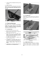
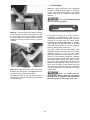
8.6 Installing table extensions
Refer to Figure 10.
Figure 10
1. Attach a table extension to the saw table.
Make sure edge bevel on table extension
faces front, to match that of saw table. Use
three screws, lock washers and flat washers
(HP-1/2/3). Lightly snug screws with 17mm
wrench.
Assembly Tip: If you are doing this without an
assistant, lift table extension vertically to the
table edge. Install center screw and washer,
and make snug. Then pivot the extension
parallel to saw table to insert the other two
screws.
2. Repeat for opposite table extension. Lightly
snug screws.
3. The front edge of table extensions must be
flush with front edge of saw table. If needed,
tap front edge of extension with a rubber
mallet to make flush. See Figure 11.
Figure 11
8.7 Leveling table extensions
Refer to Figure 12.
Level table extensions to saw table using a straight
edge. A metal straight edge is ideal, though a
carefully jointed board may also be used.
Figure 12
1. Start by tightening the three screws (17mm
wrench) under the table extension that secure
it to the saw table. Tighten these just enough
to hold the extension in place but loose
enough to change the extension height by
tapping on it.
2. Lay the straight edge (A, Figure 12) across the
saw table and extension, extending it out past
the edge of the extension as shown.
3. Move the straight edge to several places along
the table extension, as you continue to nudge
the extension level with the saw table. When
extension is level with saw table, securely
tighten each of the three screws.
4. Repeat steps 1 through 3 for opposite table
extension.
8.8 Rails and Fence
With table extensions properly aligned, the rails
and Accu-Fence
®
assembly can now be mounted
to the saw. Consult the manual, no. M-2195075Z,
that accompanies the fence.
NOTE: The two tapped holes at the ends of the
table extensions are not used. There may be
additional holes in the table’s edge that are not
required for this rail installation.
8.9 Wood Extension Table
For instructions on mounting the accessory wood
extension table, consult your Accu-Fence®
manual, document no. M-2195075Z.

15
8.10 Switch bracket
Refer to Figure 13.
Remove existing screw and washers from the
farthest left hole on the guide tube, and use them
to secure the control switch to bottom of guide
tube, as shown in Figure 13 (10mm wrench).
Figure 13
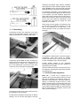
8.11 Motor cover
Refer to Figure 14.
1. At the motor side, slide the hinge pins of the
motor cover down into the cylinders.
2. To secure cover, loosen knob (B), and swing
cover shut, while pushing in on the side. The
slot (C) should slide beneath the knob.
3. Tighten knob (B).
Figure 14
8.12 Table insert
Refer to Figure 15.
Place insert into table opening (the finger hole is
toward front of saw). Verify that insert lies flush
with table surface by resting a straight edge across
it at various points. If insert is not flush along its
length, turn any of six set screws (D) to raise or
lower that area of the insert.
NOTE: If while lowering blade, the points on the
anti-kickback pawls tend to catch in the seam
between table and table insert, slightly raise that
area of the table insert above main table surface.
Figure 15
8.13 Installing and removing blade
A blade is not provided with the 64B.
1. Using front handwheel, raise blade arbor fully
and tighten lock knob.
Refer to Figures 16 and 17.
2. Remove nut (A) and flange (B), and install
blade onto arbor, making sure the teeth point
downward toward front of saw.
3. Install flange (B) and nut (A).
4. Rotate arbor until hole (C, Figure 17) aligns
with arbor lock pin (D). Push tab (E) to seat pin
into hole, and hold to prevent blade rotation.
5. Tighten nut (A) with arbor wrench.
6. Release arbor lock (E).
Figure 16

16
Figure 17
8.14 Riving knife
Refer to Figure 18.
The saw is supplied with two riving knives: One
extends above the blade and accepts the blade
guard; the other is a low-profile knife that acts
alone for non-through cutting.
To install a riving knife:
1. Remove table insert, and raise arbor all the
way up.
2. Slide prongs of riving knife into slot between
block (F, Figure 18) and plate (G), and push
riving knife down as far as it will go.
3. Push lever (H) downward, toward blade, until
tight.
4. The riving knife must be parallel to saw blade.
See section 10.5.
Figure 18
8.15 Blade guard
Refer to Figure 18.
1. Lift the anti-kickback pawls (I) and secure
them with the latch (J).
2. Push guard down so that the pins slide into the
slots in the riving knife, then pull guard
backward to seat.
3. Secure with top latch (K).
4. The transparent guard leaves (L) should drop
freely to the table.
5. Lift the latch (J) to free the pawls. Pawls must
be lowered into operating position before using
the saw!
9.0 Electrical connections
Electrical connections must
be made by a qualified electrician in
compliance with all relevant codes. This
machine must be properly grounded to help
prevent electrical shock and possible fatal
injury.
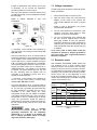
The 64B table saw is rated at 115/230V power, and
is pre-wired for 115 volt. The table saw comes with
a plug designed for use on a circuit with a
grounded outlet that looks like the one pictured in
A, Figure 19.
Before connecting to power source, be sure switch
is in off position.
It is recommended that the table saw, when
operated on 115 volt power, be connected to a
dedicated 30 amp circuit with a 30 amp circuit
breaker or time-delay fuse marked “D”. When
operated on 230 volt power, it is recommended
that the table saw be connected to a dedicated 20
amp circuit with a 20 amp circuit breaker or time-
delay fuse marked “D”. Local codes take
precedence over recommendations.
9.1 Grounding instructions
1. All Grounded, Cord-connected Tools:
In the event of a malfunction or breakdown,
grounding provides a path of least resistance for
electric current to reduce the risk of electric shock.
This tool is equipped with an electric cord having
an equipment-grounding conductor and a
grounding plug. The plug must be inserted into a
matching outlet that is properly installed and
grounded in accordance with all local codes and
ordinances.
Do not modify the plug provided - if it will not fit the
outlet, have the proper outlet installed by a
qualified electrician.
Improper connection of the equipment-grounding
conductor can result in a risk of electric shock. The
conductor with insulation having an outer surface
that is green with or without yellow stripes is the
equipment-grounding conductor.

17
If repair or replacement of the electric cord or plug
is necessary, do not connect the equipment-
grounding conductor to a live terminal.
Use only 3-wire extension cords that have 3-prong
grounding plugs and 3-pole receptacles that accept
the tool's plug.
Repair or replace damaged or worn cord
immediately.
Figure 19
2. Grounded, cord-connected tools intended for
use on a supply circuit having a nominal rating less
than 150 volts:
This tool is intended for use on a circuit that has an
outlet that looks like the one illustrated in A, Figure
19. An adapter, shown in B and C, may be used to
connect this plug to a 2-pole receptacle as shown
in B if a properly grounded outlet is not available.
The temporary adapter should be used only until a
properly grounded outlet can be installed by a
qualified electrician. This adapter is not permitted
in Canada. The green-colored rigid ear, lug, and
the like, extending from the adapter must be
connected to a permanent ground such as a
properly grounded outlet box.
3. Grounded, cord-connected tools intended for
use on a supply circuit having a nominal rating
between 150 - 250 volts, inclusive:
This tool is intended for use on a circuit that has an
outlet that looks like the one illustrated in D, Figure
19. The tool has a grounding plug that looks like
the plug illustrated in D. Make sure the tool is
connected to an outlet having the same
configuration as the plug. No adapter is available
or should be used with this tool. If the tool must be
reconnected for use on a different type of electric
circuit, the reconnection should be made by
qualified service personnel; and after reconnection,
the tool should comply with all local codes and
ordinances.
Check with a qualified
electrician or service personnel if the
grounding instructions are not completely
understood, or if in doubt as to whether the
tool is properly grounded. Failure to comply
may cause serious or fatal injury.
9.2 Voltage conversion
If 230V single phase operation is desired, follow
these instructions:
1. Disconnect table saw from power source.
2. Open the motor junction box, and consult the
diagram on the inside of the junction box
cover. Similar diagrams are shown in section
17.0.
NOTE: In case of discrepancy, the junction
box label takes precedence.
3. The four motor leads are connected for 115V
operation; reconnect these leads for 230V
operation, as shown in the diagrams.
4. The 115 volt attachment plug, supplied with
the saw, must be replaced with a UL/CSA
listed plug suitable for 230 volt operation.
Consult an electrician for proper procedures to
install the plug. The saw must comply with all
local and national codes after the 230 volt plug
is installed.
In all cases (115V or 230V) make certain the
receptacle in question is properly grounded. If
you are not sure, have a registered electrician
check the receptacle.
9.3 Extension cords
USE PROPER EXTENSION CORD. Make sure
your extension cord is in good condition. When
using an extension cord, be sure to use one heavy
enough to carry the current your product will draw.
An undersized cord will cause a drop in line voltage
resulting in loss of power and overheating. Table 1
shows correct size to use depending on cord
length and nameplate ampere rating. If in doubt,
use the next heavier gauge. The smaller the gauge
number, the heavier the cord.
Ampere
Rating
Volts
Total length of
cord in feet
More
Than
Not
More
Than
120
240
25
50
50
100
100
200
150
300
AWG
00 06 18 16 16 14
06 10 18 16 14 12
10 12 16 16 14 12
12 16 14 12
Not
Recommended
Extension Cord Recommendations
Table 1

18
9.4 Switch lockout
The table saw is equipped with a push-button
switch that will accept a safety padlock, as shown
in Figure 20. To safeguard your machine from
unauthorized operation and accidental starting by
young children, the use of a padlock (not included)
is highly recommended. Place the key in a location
that is inaccessible to children and others not
qualified to use the tool.
Figure 20: Switch Lock Out
10.0 Adjustments
10.1 Fence alignment
Before using the Accu-Fence
®
, verify that it is
properly aligned with the blade. Consult the
manual, no. M-2195075Z, that accompanied the
fence.
10.2 Blade raising/tilt mechanism
Do not try to force tilting
mechanism past the 45º or 90º stops. This may
cause blade to go out of alignment.
Refer to Figure 21:
To raise or lower blade, loosen lock knob (A) and
turn handwheel (B) on front of saw until desired
height is reached. Tighten lock knob. The blade
should be adjusted about 1/8" above top surface of
material being cut.
To tilt blade, turn lock knob (C) counter-clockwise
to loosen, turn handwheel (D) until desired angle is
obtained, and retighten lock knob (C).
Figure 21
10.3 Miter gauge
Refer to Figure 22.
10.3.1 Setting miter angle
The precision miter gauge has a rack and pinion
adjustment for setting the angle. To operate:
1. Slide miter gauge into one of the slots on table
top.
2. Loosen lock handle (A, Figure 22) by turning
counterclockwise.
3. Pull out spring-loaded knob (C) and rotate
knob until body (B) of miter gauge is at the
desired angle as indicated on the scale.
4. Tighten lock handle (A).
10.3.2 Indent settings
There are indents at the 0º, 30º and 45º right and
left positions. At these settings, release knob (C) to
engage stop rod. Then tighten lock handle (A).
Note: Do not rely solely on the indents for an
accurate setting. After the stop rod engages at the
0º, 30º and 45º positions, make a fine adjustment
with the knob (C) if necessary, setting it against the
scale indicator (G).
10.3.3 Extension plate
The extension plate (D, Figure 22) can be adjusted
by sliding to the right or left or removed entirely.
To adjust, loosen two lock handles (E), position the
extension plate and retighten lock handles. Make
sure end of extension plate is not in the blade’s
path.
NOTE: The lock handles (E) are adjustable. Pull
out on a handle, rotate it to different position, then
release, making sure it seats itself upon the pin.
To remove extension plate, slide it completely off
and remove lock handles (E) and mounting
hardware.
10.3.4 Calibration
1. Place miter gauge in one of the slots on the
table top.
2. Set miter gauge at 90º to blade (0º setting on
the scale) by loosening lock handle (A), then
pulling out spring-loaded knob (C) and turning
the body (B) until 0º is indicated on scale.
3. Measure the accuracy of the gauge against
the slot with a combination square.
If adjustment is necessary:
4. Adjust body (B) until it is perfectly square (90º)
to miter slot.
5. Tighten lock handle (A).
6. Verify that scale indicator (G) reads 0º. If
further adjustment is needed:

19
7. Loosen screw (F) and adjust indicator (G) until
it reads 0º.
8. Tighten screw (F).
NOTE: The bar of the miter gauge has two slots
with set screws (H). Adjust these set screws (4mm
hex key) to eliminate any play between bar and
miter slot.
Figure 22
10.4 Positive blade stops
The stops for 90°, 45° blade tilt, and elevation
settings have all been factory set, and should
require no immediate adjustment. The settings
should be confirmed by the operator, however, and
especially if cuts become inaccurate.
10.4.1 90° Blade stop
1. Disconnect machine from power source.
2. Make sure table insert has been leveled with
table surface. See section 8.12.
3. Raise blade all the way, and place a 90°
square on the table and against the blade
(Figure 23). Make sure that a blade tooth does
not obstruct the actual reading.
4. Tilt blade with handwheel as needed until
square and blade are flush.
5. If adjustment is required, loosen the two
setscrews on 90° stop collar (A, Figure 25 –
3mm hex key) and rotate collar along the lead
screw to needed position. Verify the new
setting.
6. Loosen screw on pointer (B, Figure 25), and
adjust pointer to zero. Retighten screw.
Figure 23
10.4.2 45° Blade stop
Repeat steps 1 through 4 above for 45° setting, as
shown in Figure 24. The 45° stop is shown at C,
Figure 25.
Figure 24
Figure 25
10.4.3 Blade elevation stops
Lower blade all the way; it should drop completely
below the table surface. If it does not, adjust
amount of drop using two stop screws (D, Figure
26).

20
Figure 26
10.5 Riving knife alignment
The riving knife must be aligned with the blade for
proper and safe operation of the table saw. This
has been set by the manufacturer, but should be
verified by the operator.
1. Disconnect machine from power source.
2. Install riving knife and tighten lever (H, Figure
18).
3. Place a straight edge against blade and riving
knife; it should lie flush against both surfaces.
See Figure 27.
4. If correction is needed, remove straight edge,
table insert, and riving knife and locate four set
screws (E, Figure 28) through the corner holes
of clamp block.
5. Rotate any of the four set screws as needed to
tilt the angle of the clamp block, and thus the
riving knife.
6. Install riving knife and verify the setting with
the straight edge. Make further adjustments as
needed.
Figure 27
Figure 28
10.6 Low profile riving knife
A low profile riving knife is included with your saw.
It mounts and adjusts in the same manner as the
standard riving knife. The low profile riving knife
sits just below top of blade and is used for making
non-through cuts. The blade guard is not used with
this knife, so extra precautions should be taken
during operation.
10.7 Trunnion adjustment
If backlash develops in the trunnion assembly, it
can be adjusted out using the screws (6mm hex
key) at front and back of cabinet (F, Figure 25
shows front screw). Front and rear trunnions
should receive the same amount of spring tension
from the screws.
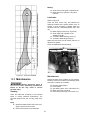
10.8 Table to blade alignment
Refer to Figures 29 and 30.
The table has been squared to the blade by the
manufacturer and no adjustment is necessary now.
If cuts become inaccurate, check table-blade
squareness and correct if necessary. Use the miter
slot to do this:
1. Disconnect saw from power source.
2. Raise blade to maximum height.
3. Mark one tooth (A, Figure 29) with a grease
pencil and position the tooth slightly above the
top edge of table at the front.
4. Raise the miter gauge slightly out of its slot to
serve as a shoulder. Using a sliding square (B)
against the side of the bar, slide the scale over
until it touches the tip of the blade, and lock
the scale in position.
Page is loading ...
Page is loading ...
Page is loading ...
Page is loading ...
Page is loading ...
Page is loading ...
Page is loading ...
Page is loading ...
Page is loading ...
Page is loading ...
Page is loading ...
Page is loading ...
Page is loading ...
Page is loading ...
Page is loading ...
Page is loading ...
Page is loading ...
Page is loading ...
Page is loading ...
Page is loading ...
-
 1
1
-
 2
2
-
 3
3
-
 4
4
-
 5
5
-
 6
6
-
 7
7
-
 8
8
-
 9
9
-
 10
10
-
 11
11
-
 12
12
-
 13
13
-
 14
14
-
 15
15
-
 16
16
-
 17
17
-
 18
18
-
 19
19
-
 20
20
-
 21
21
-
 22
22
-
 23
23
-
 24
24
-
 25
25
-
 26
26
-
 27
27
-
 28
28
-
 29
29
-
 30
30
-
 31
31
-
 32
32
-
 33
33
-
 34
34
-
 35
35
-
 36
36
-
 37
37
-
 38
38
-
 39
39
-
 40
40


Powermatic 1791230K User manual
- Type
- User manual
- This manual is also suitable for
Ask a question and I''ll find the answer in the document
Finding information in a document is now easier with AI
Related papers
-
Powermatic 64B, 1.75 HP 115/230V, 50" Fence User manual
-
-
-
-
-
-
-
-
-