Comnet FDX72SHR Series User manual

Type
User manual

Comnet FDX72SHR Series is a multi-protocol RS232/422/485 data transceiver that offers reliable data transmission for traffic signalization and communications networks. It supports full-duplex or two half-duplex channels, ensuring efficient data exchange. The device features self-healing ring operation, providing redundancy and minimizing downtime in case of fiber breaks. It employs wave division multiplexing, requiring only one optical fiber for a fully self-healing ring. The FDX72SHR also includes LED indicators for monitoring equipment status and fiber breaks, simplifying troubleshooting.

Comnet FDX72SHR Series is a multi-protocol RS232/422/485 data transceiver that offers reliable data transmission for traffic signalization and communications networks. It supports full-duplex or two half-duplex channels, ensuring efficient data exchange. The device features self-healing ring operation, providing redundancy and minimizing downtime in case of fiber breaks. It employs wave division multiplexing, requiring only one optical fiber for a fully self-healing ring. The FDX72SHR also includes LED indicators for monitoring equipment status and fiber breaks, simplifying troubleshooting.

INS_FDX72SHR_REV–
02/29/12
PAGE 1
INSTALLATION AND OPERATION MANUAL
FDX72(M,S)1SHR
MULTI-PROTOCOL RS232/422/485 DATA TRANSCEIVER
FEATURING SELF-HEALING RING OPERATION
The ComNet™ FDX72(M,S)1SHR series Self-Healing Ring Transceiver unit is
a fully-digital transceiver designed for implementing full RS232, RS422 or
RS485 2 or 4-wire traffic signalization/communications data networks of the
highest possible reliability. A network of FDX72SHR units can support one full-
duplex data channel or two half-duplex data channels. Full data re-clocking and
regeneration permit an almost unlimited number of transceiver/controller units
to be used within the network. These environmentally hardened transceivers are
ideal for use in unconditioned out-of-plant or roadside installations.
Utilizing wave division multiplexing technology (WDM), only one optical fiber is
required between units to implement a fully self-healing ring. Two FDX72SHR
units can be used in a redundant point-to-point topology.
Bi-color (Red/Green) LED indicators are provided for rapidly ascertaining
equipment operating status including the location of fiber breaks. See Figure 7
on Page 5 for an explanation of LED indications.
These units are interchangeable between stand-alone or card-cage mount
configurations. See Figure A on Page 7 for mounting instructions.
See Figures 1 – 8 for complete installation details.
INS_FDX72SHR_REV–
02/29/12
PAGE 2
FIGURE 2 – FDX72SHR
FIGURE 1 – FDX72SHR FIBER CONNECTIONS
INSTALLATION AND OPERATION MANUAL FDX72(M,S)1SHR
REAR PANELFRONT PANEL
TECH SUPPORT: 1.888.678.9427
MULTIMODE OR SINGLE MODE OPTICAL
FIBER (DEPENDING ON MODEL)
Optical Port A must be connected to Optical
Port B on another FDX72SHR unit.
Similarly, Optical Port B must be connected
to Optical Port A on another FDX72SHR unit.
See Figure 8 on Page 6.
BLACK
BLACK WITH WHITE STRIPE
Power Supply:
Surface Mount: 8–15 VDC @ 4W
Rack Mount: From Rack
NOTE: Remove Electrical Connector
for Rack Mount Units
Ring Length Switch
See Figure 4
Data Format Switch
See Figure 3
7-Pin Data Connector
See Figures 5 & 6
LED Indicators
See Figure 7
INS_FDX72SHR_REV–
02/29/12
PAGE 3
FIGURE 3 – DATA FORMAT SWITCH POSITIONS
TECH SUPPORT: 1.888.678.9427
INSTALLATION AND OPERATION MANUAL FDX72(M,S)1SHR
Switch
Lower bank of switches
located on front panel.
The first two switches set the
data type, the third sets the
Master/Remote Mode.
RS232 Data
1 2 3
RS422, Bi-Phase or
Manchester Data
1 2 3
RS485
4-Wire Data
1 2 3
Remote Mode
1 2 3
RS485 2-Wire, Sensornet
Data
1 2 3
Master Mode
1 2 3
There are two virtual data channels shared between all FDX72SHR units in a system: a Master channel and a Remote channel.
The Master/Remote Mode switch sets the data channel used by the equipment connected to each FDX72SHR unit in the system.
The behavior of a Master and Remote depends on the data type (set by switches 1 and 2):
RS232, RS422, RS485 (4-wire):
Units in Master Mode transmit data to all units set to Remote Mode.
Units in Remote Mode transmit data to all units set to Master Mode.
There is no limit to the number of Masters or Remotes in a system as long as the equipment connected to the FDX72SHR can
handle multiple Masters and multiple Remotes. Most applications requiring Master/Remote communications would use just one
Master and multiple Remotes. Masters can communicate with all Slaves, but not with other Masters. Remotes can communicate
with all Masters, but not with other Remotes.
RS485 (2-wire):
Units in Master Mode transmit data to all units set to Master Mode.
Units in Remote Mode transmit data to all units set to Remote Mode.
The concept of Master and Remote are not used with RS485 (2-wire) mode. Rather, the Master/Remote Mode switch simply sets
which of two independent data channels each unit will use. All Masters can communicate with each other, but not with Remotes.
All Remotes can communicate with each other, but not with Masters.
}
INS_FDX72SHR_REV–
02/29/12
PAGE 4
FIGURE 4 – RING LENGTH SWITCH POSITIONS
TECH SUPPORT: 1.888.678.9427
INSTALLATION AND OPERATION MANUAL FDX72(M,S)1SHR
Switch
Upper bank of
switches located
on front panel.
For most applications, the Ring Length Switch can be left at
default setting. For high data rate applications (>250Kbps) ring
length should be set to minimize turn-around time.
FIGURE 5 – DATA CONNECTIONS
RS232
Customer
Equipment FDX72SHR
Customer
EquipmentFDX72SHR
RS422
Bi-phase or
Manchester
DIN(+)
DIN(–)
DOUT(+)
DOUT(–)
Data Out (+)
Data Out (–)
2-Wire
RS485,
Sensornet
DIN(+)
DIN(–)
DIN(+)
DIN(–)
Data (A)
Data (B)
Data Transmit
Data Receive
Signal Ground
DIN(–)
DOUT(–)
GND
DOUT(–)
DIN(–)
GND
4-Wire
RS485
DIN(+)
DIN(–)
DOUT(+)
DOUT(–)
DOUT(+)
DOUT(–)
DIN(+)
DIN(–)
Data Out (A)
Data Out (B)
Data In (A)
Data In (B)
DIN(+)
DIN(–)
DOUT(+)
DOUT(–)
DOUT(+)
DOUT(–)
DIN(+)
DIN(–)
Data Out (+)
Data Out (–)
Data In (+)
Data In (–)
Data In (+)
Data In (–)
Data (A)
Data (B)
Data Receive
Data Transmit
Signal Ground
Data In (A)
Data In (B)
Data Out (A)
Data Out (B)
Data In (+)
Data In (–)
Data Out (+)
Data Out (–)
Switch Position
Resulting Max Ring Length
1 2 3
ON ON ON 100 km (default)
ON ON OFF 75 km
ON OFF ON 50 km
ON OFF OFF 20 km
OFF ON ON 10 km
OFF ON OFF 5 km
OFF OFF ON 2 km
OFF OFF OFF 1 km
}
INS_FDX72SHR_REV–
02/29/12
PAGE 5
TECH SUPPORT: 1.888.678.9427
INSTALLATION AND OPERATION MANUAL FDX72(M,S)1SHR
FIGURE 7 – LED INDICATORS
LINK A LINK B DIN DOUT STATUS POWER
GREEN Unit In Sync Unit In Sync Data Activity Data Activity System OK. No Alarm Unit Powered Up
RED Unit Not In Sync Unit Not In Sync Fault Detected. Alarm Condition.
OFF No Data Activity No Data Activity Unit Powered Down
FIGURE 6 – 7-PIN DATA CONNECTOR
BIAS Current limited +5V connection. This terminal can be used as a
connection for pull-up resistors, if required.
ALARM Alarm relay output. Indicates fault conditions. The relay is internally
connected to the GND terminal when no faults are detected (i.e.
a normally closed relay). The relay circuit opens when a fault is
detected anywhere in the system.
GND: Signal ground reference. This terminal can be also be used as a
connection for pull-down resistors, if required.
DIN+/DIN- Electrical data inputs. See Figure 5 for data connections.
DOUT+/DOUT- Electrical data outputs. See Figure 5 for data connections.
INS_FDX72SHR_REV–
02/29/12
PAGE 6
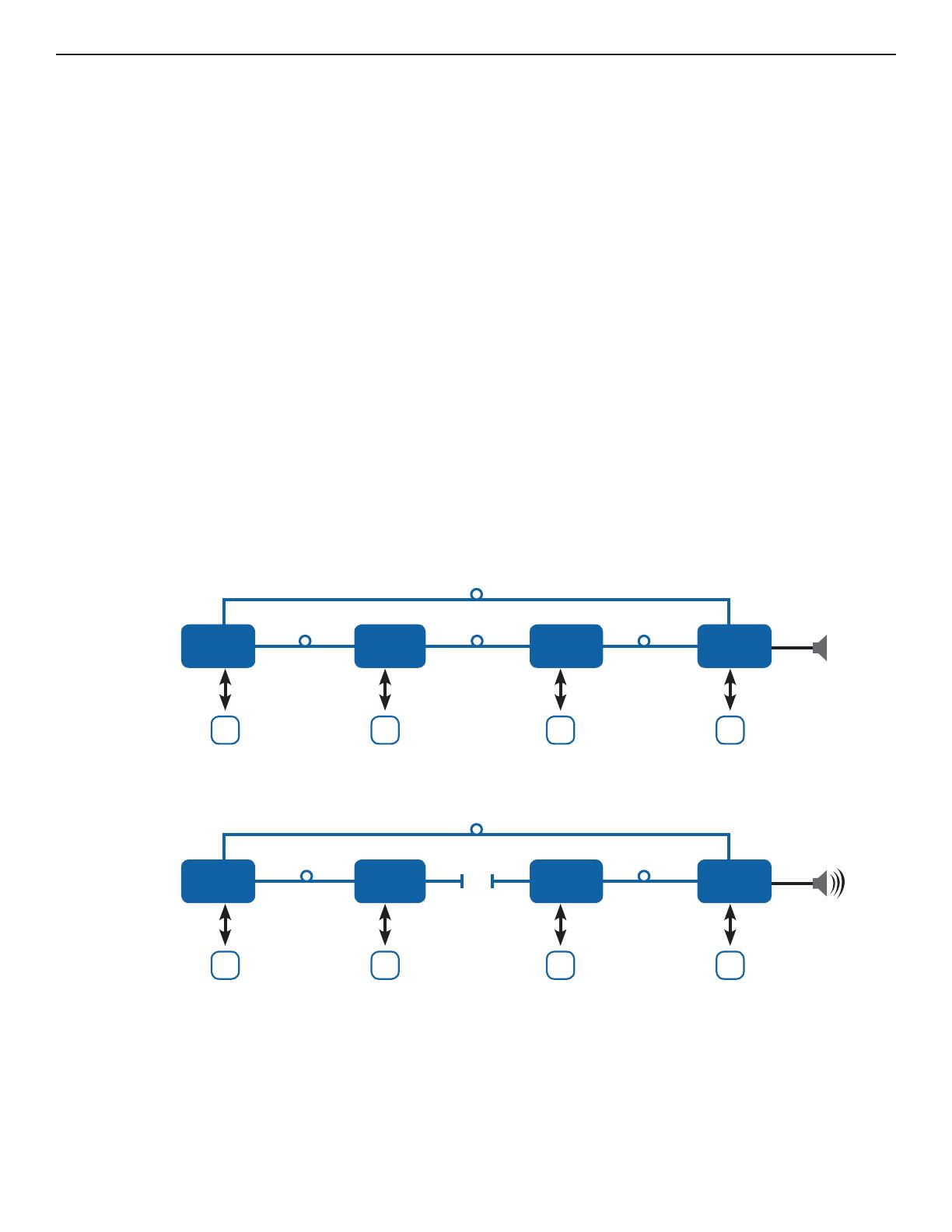
FIGURE 8 – FAULT CONDITIONS
TECH SUPPORT: 1.888.678.9427
INSTALLATION AND OPERATION MANUAL FDX72(M,S)1SHR
A fault condition is when a FDX72SHR unit system loses power or optical link. The FDX72SHR provides three indicators to help
identify when and where fault conditions occur in a system:
1. ALARM relay output
2. STATUS LED
3. LINK A and LINK B LEDs
When a fault occurs, the ALARM relay on every FDX72SHR in the system goes from closed to open. In addition, the STATUS LED
on every FDX72SHR in the system goes from solid green to solid red. The LINK A and LINK B LEDs can then be used to identify
the actual location of the fault based on their color and pattern:
Solid Green Optical link has been established between this optical port and the adjacent FDX72SHR over fiber.
Furthermore, every other unit in the system is also reporting that link has been established. There are no faults
in the system.
Solid Red Optical link over this port has been lost.
This could be due to a broken fiber, a bad connection, or loss of power at the adjacent unit.
Blinking
Green/Red Optical link has been established between this optical port and the adjacent FDX72SHR over fiber.
However, a fault condition has been detected somewhere in the system. The LINK LED will be green for a
period of time, and then flash red some number of times. The number of red flashes indicates the location of
the fault by “hops” around the ring. If the LED flashes red three times, then the location of the fault is three hops
away (i.e. three FDX72SHR units away). For larger systems with faults greater than 9 hops away, the LED will
use a combination of long and short red flashes. Each long flash indicates 10 hops. Each short flash indicates
1 hop. For example, a fault 47 hops away would be encoded as 4 long red flashes, followed immediately by 7
short red flashes. The pattern repeats indefinitely until the fault is resolved.
The diagram above shows the connections for a system of four FDX72SHR units. The fourth unit has an audible alarm connected to its
ALARM relay. The alarm relay is normally closed. Every unit’s LINK A, LINK B, and STATUS LEDs will be solid green.
The diagram above shows how this system will respond to an optical fiber break between Unit 2 and Unit 3. The ALARM relay on
every node will go from closed to an open circuit to indicate an alarm condition and the STATUS LED on every node will go from
solid green to solid red. The audible alarm connected to unit 4 will sound. The LINK A and LINK B LEDs on each unit will identify
where the fault occurred:
Unit 1 The LINK A LED will be green for a time, then flash red 1 time. The LINK B LED will be green for a time, then flash red 2 times.
Unit 2 The LINK A LED will be solid red. The LINK B LED will be green for a time, then flash red 3 times.
Unit 3 The LINK A LED will be green for a time, then flash red 3 times. The LINK B LED will be solid red.
Unit 4 The LINK A LED will be green for a time, then flash red 2 times. The LINK B LED will be green for a time, then flash red 1 time.
ALARM
OPTICAL FIBER
FDX72S1SHR
Unit 1
D
FDX72S1SHR
Unit 3
D
FDX72S1SHR
Unit 2
D
FDX72S1SHR
Unit 4
D
AB
DIN/DOUT DIN/DOUT DIN/DOUT DIN/DOUT
A
B
A
B
A
B
ALARM
OPTICAL FIBER
FDX72S1SHR
Unit 1
D
FDX72S1SHR
Unit 3
D
FDX72S1SHR
Unit 2
D
FDX72S1SHR
Unit 4
D
AB
DIN/DOUT DIN/DOUT DIN/DOUT DIN/DOUT
A
B
A
B
BROKEN
FIBER
A
B
EXAMPLE
INS_FDX72SHR_REV–
02/29/12
PAGE 7
© 2012 Communications Networks Corporation. All Rights Reserved. “ComNet” and the “ComNet Logo” are registered trademarks of Communication Networks, LLC.
3 CORPORATE DRIVE | DANBURY, CT 06810 | USA
T: 203.796.5300 | F: 203.796.5303 | TECH SUPPORT: 1.888.678.9427 | INFO@COMNET.NET
8 TURNBERRY PARK ROAD | GILDERSOME | MORLEY | LEEDS, UK LS27 7LE
T: +44 (0)113 307 6400 | F: +44 (0)113 253 7462 | INFO-EUROPE@COMNET.NET
INSTALLATION CONSIDERATIONS
This fiber-optic link is supplied as a Standalone/Rack module. Units
should be installed in dry locations protected from extremes of
temperature and humidity.
C1-US, C1-EU, C1-AU OR C1-CH CARD CAGE RACKS
CAUTION: Although the units are hot-swappable and may be installed
without turning power off to the rack, ComNet recommends that
the power supply be turned off and that the rack power supply
is disconnected from any power source. Note: Remove electrical
connector before installing in card cage rack.
1. Make sure that the card is oriented right side up, and slide it into the
card guides in the rack until the edge connector at the back of the
card seats in the corresponding slot in the rack’s connector panel.
Seating may require thumb pressure on the top and bottom of the
card’s front panel.
CAUTION: Take care not to press on any of the LEDs.
2. Tighten the two thumb screws on the card until the front panel of the
card is seated against the front of the rack.
WARNING: Unit is to be used with a Listed Class 2 or LPS power supply.
IMPORTANT SAFEGUARDS:
A) Elevated Operating Ambient - If installed in a closed or multi-unit rack
assembly, the operating ambient temperature of the rack environment may
be greater than room ambient. Therefore, consideration should be given to
installing the equipment in an environment compatible with the maximum
ambient temperature (Tma) specified by the manufacturer.
B) Reduced Air Flow - Installation of the equipment in a rack should be such
that the amount of air flow required for safe operation of the equipment is not
compromised.
MECHANICAL INSTALLATION INSTRUCTIONS
FIGURE A
Dimensions are for a standard ComNet™ one slot module
.156 [3.96 mm]
.313 [7.95 mm]
  • Page 1 1
  • Page 2 2
  • Page 3 3
  • Page 4 4
  • Page 5 5
  • Page 6 6
  • Page 7 7

Comnet FDX72SHR Series User manual

Type
User manual

Comnet FDX72SHR Series is a multi-protocol RS232/422/485 data transceiver that offers reliable data transmission for traffic signalization and communications networks. It supports full-duplex or two half-duplex channels, ensuring efficient data exchange. The device features self-healing ring operation, providing redundancy and minimizing downtime in case of fiber breaks. It employs wave division multiplexing, requiring only one optical fiber for a fully self-healing ring. The FDX72SHR also includes LED indicators for monitoring equipment status and fiber breaks, simplifying troubleshooting.

Ask a question and I''ll find the answer in the document

Finding information in a document is now easier with AI