EN
77-1474-R20 (3/2018)4 / 8www.carlisleft.com
INSTALLATION
Air Supply
Air supplies (compressors, etc.)
shall be sited in a non-hazardous
area with a filter on the air
intake system to prevent the
ingress of dust or similar foreign
material into the parts where
compression takes place.
!
WARNING
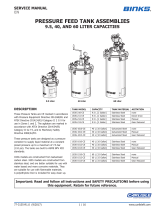
AIR MOTOR LUBRICATION
An automatic air line filter/
lubricator should be installed in
the air supply line no more than
0.5m (19 in) from the air motor.
The filter should be 5 micron.
Install the lubricator level with
or above the motor so the oil
mist will blow directly into or
down into the motor (see Fig. 1).
!
WARNING
Fill the oil reservoir with SAE 10W
motor oil. Adjust lubricator to feed 1
drop of oil for every 1400 litres (50 cfm)
of air or 1 drop per minute for
continuous running.
KIT ASSEMBLY
Only Use the proper Lid assembly
31-428 with this Agitator.
1. Remove the propeller (10) from the
shaft (3) by loosening the lock screw
(9).
2. Unscrew the locknut (5) from the
housing, and remove washer (8).
3. Insert the shaft into the aperture in
the lid and rotate until the pin locates
in the slot.
4. Slide the washer (8) over the shaft,
the raised centre towards the
locknut.
5. Replace the locknut (5) and tighten.
6. Replace the propeller (10) and secure
with screw (9).
7. Place the lid assembly over the pail
or drum.
Make sure the pail has a minimum
depth of 340 mm for a 25 mm
clearance, or the propeller may
contact the bottom and create
possible sparking hazards.
!
CAUTION
8. Before operating any of these
agitators lubricate the air motor by
adding 4 or 5 drops of SAE 10 weight
oil into the air fitting.
9. Close the Air Adjusting valve (2) by
rotating clockwise.
10. Connect the airline to the valve (2).
The Agitator is now ready for use.
OPERATION
1. Before turning on the air supply,
screw in the air adjusting valve (2)
fully. Turn on the air supply and
slowly open up the air adjusting
valve.
2. The optimum speed is dependent on
the type of coating material being
agitated. If the speed it too high, the
propeller will cavitate and aerate the
material.
3. It is not recommended to run the
motor faster than 1000 rpm. Do not
exceed 3000 rpm.
4. When the tank is empty, the motor
speed will rise. Stop the motor to
avoid unnecessary high speed
running. Prolonged high speed
running may result in premature
wear and failure of the motor.
PREVENTATIVE
MAINTENANCE
1. Turn off the main air supply to the
Agitator with the isolator valve.
2. Check exhaust muffler for blockage.
Clean if necessary.
3. If the Air motor starts to run slowly
or is sluggish, flushing the motor
with solvent may restore its
performance due to excessive
contamination from oil, moisture and
foreign particles. Use only Gast
#AH255B Flushing Solvent or
equivalent for this.
4. This cleaning operation should only
be carried out ion a well ventilated
area.
5. Wear eye protection.
6. Do not use combustible solvents for
flushing.
7. Disconnect the airline and muffler.
Add about 100ml (4 fluid oz) of
solvent into the air intake port of the
motor. Rotate the motor by hand in
both directions for a few minutes.
8. Re-connect the airline and cover the
exhaust port with a cloth. Apply low
pressure 0.7bar (10psi) and re-start
the motor. Run until no more traces
of solvent can be seen.
9. The motor should be running
smoothly. If not, then a re-build may
be required (see Replacement of
Parts).
REPLACEMENT OF PARTS
1. Remove the propeller (10) from the
shaft (3) by loosening the lock screw
(11).
2. Unscrew the locknut (5) from the
housing, and remove washer (8).
3. Withdraw the Agitator from the
aperture in the lid.
4. Loosen the top 2 screws (9) in the
coupling (11) and remove the shaft
and coupling from the motor drive
shaft.
5. Loosen the screw (4) and separate
the motor from the housing.
Failure to operate and maintain
these agitators correctly could result
in premature motor failure and void
warranty.
If not already done so, before
operating any of these agitators
lubricate the air motor by adding
4 or 5 drops of SAE 10 weight oil
into the air fitting.
!
CAUTION