XC13N - 1.5 to 5 Ton Air Conditioner / Page 4
REFRIGERATION SYSTEM (continued)
Refrigerant Flow Control
• Units applicable to expansion valve systems or RFC
systems when matched with specic indoor coils
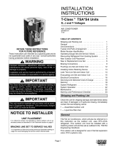
RFCIV:
• Accurately meters
refrigerant in
system
• Refrigerant control
is accomplished
by exact sizing of
refrigerant metering
orice
• The principle
involves matching
indoor coil with
proper bore size of orice in metering device
• Equalizes pressure shortly after compressor stops, unit
starts unloaded, eliminating need for additional controls
• See RFC Orice Usage Table on Page 10 for correct
matches
Optional Accessories
Expansion Valve Kits
• Field installed on certain indoor units
• See TXV Usage Table
• Chatleff-style ttings
Freezestat
• Senses suction line temperature
• Cycles compressor off when suction line temperature
falls below it’s setpoint
• Opens at 29°F and closes at 58°F
• Installs on or near the discharge line of the evaporator or
on the suction line
Loss of Charge Switch Kit
• Protects compressor from damage from low refrigerant
charge conditions
• SPST
• Normally-closed
• Automatic reset
Refrigerant Line Kits
• Refrigerant lines are shipped refrigeration clean
• Lines are cleaned, dried, pressurized and sealed at
factory
• Suction line fully insulated
• Lines are stubbed at both ends
NOTE - Not available for -060 models and must be eld
fabricated
O−RING
RFCIV METERING SYSTEM
RFCIV
ORIFICE
ORIFICE BODY
(On Coil)
SEAL
NUT SWEAT
CONNECTION
LIQUID
LINE
LIQUID
LINE SCREEN
COMPRESSOR
Scroll Compressor
• High efciency with uniform
suction ow
• Constant discharge ow, high
volumetric efciency and quiet
operation
• Low gas pulses during
compression reduces operational
sound levels
• Compressor motor is internally
protected from excessive current
and temperature
• Mufer in discharge line reduces operating sound levels
• Compressor is installed in the unit on resilient rubber
mounts for vibration free operation
Scroll Compressor Operation
• Two involute spiral scrolls matched together generate a
series of crescent-shaped gas pockets between them
• During compression, one scroll remains stationary while
the other scroll orbits around it
• Gas is drawn into the outer pocket, the pocket is sealed
as the scroll rotates
• As the spiral movement continues, gas pockets are
pushed to the center of the scrolls. Volume between the
pockets is simultaneously reduced
• When the pocket reaches the center, gas is now at high
pressure and is forced out of a port located in the center
of the xed scrolls
• During compression, several pockets are compressed
simultaneously resulting in a smooth continuous
compression cycle
• Continuous ank contact, maintained by centrifugal
force, minimizes gas leakage and maximizes efciency
• Compressor is tolerant to the effects of slugging and
contaminants. If this occurs, scrolls separate, allowing
liquid or contaminants to be worked toward the center
and discharged
Optional Accessories
Compressor Crankcase Heater
• Protects against refrigerant migration that can occur
during low ambient operation
Compressor Sound Cover
• Reinforced vinyl compressor cover
• 1-1/2 inch thick batt of berglass insulation
• Hook and loop fastening tape on all open edges
Compressor Hard Start Kit
• Single-phase units are equipped with a PSC compressor
motor
• This type of motor normally doesn’t need a potential
relay and start capacitor
• For conditions such as low voltage kit may be required
to increase the compressor starting torque
FF
FEATURES